

Page 1
GB
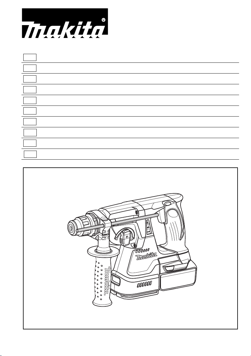
DHR242
DHR243
Cordless Combination Hammer Instruction Manual
F
Marteau Combiné sans Fil Manuel d’instructions
D
Akku-Kombi-Bohrhammer Betriebsanleitung
I
Martello multifunzione a batteria Istruzioni per l’uso
NL
Snoerloze combinatiehamer Gebruiksaanwijzing
E
Martillo Rotativo Combinado Inalámbrico
P
Martelete Combinado A Bateria Manual de instruções
DK
Akku-kombinationshammer Brugsanvisning
Manual de instrucciones
GR Φορητό σφυρί συνδυασμού
TR Kablosuz Kombine Darbeli Matkap
Οδηγίες χρήσεως
Kullanma kılavuzu
Page 2
1
2
3
4
5
6
A
B
15
12
13
14
12
012622 012128
34
7
8
012627 012628
11
10
8
9
56
012690 012689
9
78
012629 012631
2
Page 3
16
17
22
23
25
24
27
28
19
20
19 20
18
21
910
11 12
012630
001296 012624
012623
25
24
13 14
15 16
26
14
012632012625
012633 012626
3
Page 4
29
30
31
32
7
8
9
10
11
9
8
17 18
19 20
21 22
012636
002449
012684
012634
012686
33
34
012685
23 24
4
012690
012689
Page 5
11
33
34
25
012720
5
Page 6

ENGLISH (Original instructions)
Explanation of general view
1 Red indicator
2Button
3 Battery cartridge
4 Star marking
5 Switch trigger
6 Reversing switch lever
7 Quick change chuck for
SDS-plus
8 Change cover line
9 Change cover
10 Spindle
11 Quick change drill chuck
SPECIFICATIONS
Model DHR242 DHR243
Capacities
Concrete ................................................................................... 24 mm 24 mm
Steel ......................................................................................... 13 mm 13 mm
Wood ........................................................................................ 27 mm 27 mm
No load speed (min
Blows per minute .........................................................................0 – 4,700 0 – 4,700
Overall length .............................................................................. 328 mm 353 mm
Net weight ................................................................................... 3.3 kg 3.4 kg
Rated voltage ..............................................................................D.C. 18 V D.C. 18 V
–1
) .................................................................0 – 950 0 – 950
12 Rotation with hammering
13 Lock button
14 Action mode changing knob
15 Rotation only
16 Hammering only
17 Protrusion
18 Groove
19 Loosen
20 Tighten
21 Side grip
22 Bit shank
23 Bit grease
24 Bit
25 Chuck cover
O symbol
26
27 Hole
28 Depth gauge
29 Dust cup
30 Blow-out bulb
31 Chuck adapter
32 Keyless drill chuck
33 Sleeve
34 Ring
• Due to our continuing program of research and devel-
opment, the specifications herein are subject to change
without notice.
• Specifications and battery cartridge may differ from
country to country.
• Weight, with battery cartridge, according to EPTA-Pro-
cedure 01/2003
ENE043-1
Intended use
The tool is intended for hammer drilling and drilling in
brick, concrete and stone as well as for chiselling work.
It is also suitable for drilling without impact in wood,
metal, ceramic and plastic.
GEA010-1
General Power Tool Safety Warnings
WARNING Read all safety warnings and all
instructions. Failure to follow the warnings and
instructions may result in electric shock, fire and/or
serious injury.
Save all warnings and instructions for future reference.
GEB046-2
CORDLESS ROTARY HAMMER SAFETY
WARNINGS
1. Wear ear protectors. Exposure to noise can cause
hearing loss.
2. Use auxiliary handles supplied with the tool.
Loss of control can cause personal injury.
3. Hold power tools by insulated gripping surfaces,
when performing an operation where the cutting
accessory may contact hidden wiring. Cutting
accessory contacting a “live” wire may make
exposed metal parts of the power tool “live” and
could give the operator an electric shock.
4. Wear a hard hat (safety helmet), safety glasses
and/or face shield. Ordinary eye or sun glasses
are NOT safety glasses. It is also highly recommended that you wear a dust mask and thickly
padded gloves.
5. Be sure the bit is secured in place before operation.
6. Under normal operation, the tool is designed to
produce vibration. The screws can come loose
easily, causing a breakdown or accident. Check
tightness of screws carefully before operation.
7. In cold weather or when the tool has not been
used for a long time, let the tool warm up for a
while by operating it under no load. This will
loosen up the lubrication. Without proper warmup, hammering operation is difficult.
8. Always be sure you have a firm footing.
Be sure no one is below when using the tool in
high locations.
9. Hold the tool firmly with both hands.
10. Keep hands away from moving parts.
11. Do not leave the tool running. Operate the tool
only when hand-held.
12. Do not point the tool at any one in the area when
operating. The bit could fly out and injure someone seriously.
13. Do not touch the bit or parts close to the bit
immediately after operation; they may be
extremely hot and could burn your skin.
6
Page 7

14. Some material contains chemicals which may be
toxic. Take caution to prevent dust inhalation
and skin contact. Follow material supplier safety
data.
SAVE THESE INSTRUCTIONS.
WARNING:
DO NOT let comfort or familiarity with product
(gained from repeated use) replace strict adherence
to safety rules for the subject product. MISUSE or
failure to follow the safety rules stated in this
instruction manual may cause serious personal
injury.
ENC007-7
IMPORTANT SAFETY INSTRUCTIONS
FOR BATTERY CARTRIDGE
1. Before using battery cartridge, read all instructions and cautionary markings on (1) battery
charger, (2) battery, and (3) product using battery.
2. Do not disassemble battery cartridge.
3. If operating time has become excessively
shorter, stop operating immediately. It may
result in a risk of overheating, possible burns
and even an explosion.
4. If electrolyte gets into your eyes, rinse them out
with clear water and seek medical attention right
away. It may result in loss of your eyesight.
5. Do not short the battery cartridge:
(1) Do not touch the terminals with any conduc-
tive material.
(2) Avoid storing battery cartridge in a container
with other metal objects such as nails, coins,
etc.
(3) Do not expose battery cartridge to water or
rain.
A battery short can cause a large current flow,
overheating, possible burns and even a breakdown.
6. Do not store the tool and battery cartridge in
locations where the temperature may reach or
exceed 50°C (122°F).
7. Do not incinerate the battery cartridge even if it
is severely damaged or is completely worn out.
The battery cartridge can explode in a fire.
8. Be careful not to drop or strike battery.
9. Do not use a damaged battery.
SAVE THESE INSTRUCTIONS.
Tips for maintaining maximum battery life
1. Charge the battery cartridge before completely
discharged.
Always stop tool operation and charge the battery cartridge when you notice less tool power.
2. Never recharge a fully charged battery cartridge.
Overcharging shortens the battery service life.
3. Charge the battery cartridge with room temperature at 10°C – 40°C (50°F – 104°F). Let a hot battery cartridge cool down before charging it.
4. Charge the battery cartridge once in every six
months if you do not use it for a long period of
time.
FUNCTIONAL DESCRIPTION
CAUTION:
• Always be sure that the tool is switched off and the battery cartridge is removed before adjusting or checking
function on the tool.
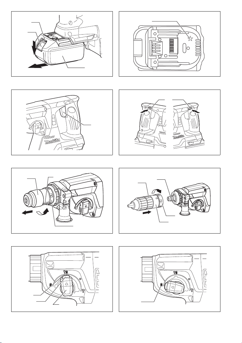
Installing or removing battery cartridge (Fig. 1)
CAUTION:
• Hold the tool and the battery cartridge firmly when
installing or removing battery cartridge. Failure to
hold the tool and the battery cartridge firmly may cause
them to slip off your hands and result in damage to the
tool and battery cartridge and a personal injury.
• Always switch off the tool before installing or removing
of the battery cartridge.
• To remove the battery cartridge, slide it from the tool
while sliding the button on the front of the cartridge.
• To install the battery cartridge, align the tongue on the
battery cartridge with the groove in the housing and slip
it into place. Always insert it all the way until it locks in
place with a little click. If you can see the red indicator
on the upper side of the button, it is not locked completely. Install it fully until the red indicator cannot be
seen. If not, it may accidentally fall out of the tool, causing injury to you or someone around you.
• Do not use force when installing the battery cartridge. If
the cartridge does not slide in easily, it is not being
inserted correctly.
Battery protection system (Lithium-ion battery
with star marking) (Fig. 2)
Lithium-ion batteries with a star marking are equipped
with a protection system. This system automatically cuts
off power to the tool to extend battery life.
The tool will automatically stop during operation if the
tool and/or battery are placed under one of the following
conditions:
• Overloaded:
The tool is operated in a manner that causes it to draw
an abnormally high current.
In this situation, release the trigger switch on the tool
and stop the application that caused the tool to become
overloaded. Then pull the trigger switch again to
restart.
If the tool does not start, the battery is overheated. In
this situation, let the battery cool before pulling the trigger switch again.
• Low battery voltage:
The remaining battery capacity is too low and the tool
will not operate. In this situation, remove and recharge
the battery.
Switch action (Fig. 3)
CAUTION:
• Before inserting the battery cartridge into the tool,
always check to see that the switch trigger actuates
properly and returns to the “OFF” position when
released.
To start the tool, simply pull the switch trigger. Tool speed
is increased by increasing pressure on the switch trigger.
Release the switch trigger to stop.
7
Page 8

Reversing switch action (Fig. 4)
This tool has a reversing switch to change the direction
of rotation. Depress the reversing switch lever from the A
side for clockwise rotation or from the B side for counterclockwise rotation.
When the reversing switch lever is in the neutral position,
the switch trigger cannot be pulled.
CAUTION:
• Always check the direction of rotation before operation.
• Use the reversing switch only after the tool comes to a
complete stop. Changing the direction of rotation
before the tool stops may damage the tool.
• When not operating the tool, always set the reversing
switch lever to the neutral position.
Changing the quick change chuck for SDS-plus
For Model DHR243
The quick change chuck for SDS-plus can be easily
exchanged for the quick change drill chuck.
Removing the quick change chuck for SDS-plus
(Fig. 5)
CAUTION:
• Before removing the quick change chuck for SDS-plus,
always remove the bit.
Grasp the change cover of the quick change chuck for
SDS-plus and turn in the direction of the arrow until the
change cover line moves from the symbol to the
symbol. Pull forcefully in the direction of the arrow.
Attaching the quick change drill chuck (Fig. 6)
Check the line of the quick change drill chuck shows the
symbol. Grasp the change cover of the quick change
drill chuck and set the line to the symbol.
Place the quick change drill chuck on the spindle of the
tool.
Grasp the change cover of the quick change drill chuck
and turn the change cover line to the symbol until a
click can clearly be heard.
Selecting the action mode
Rotation with hammering (Fig. 7)
For drilling in concrete, masonry, etc., depress the lock
button and rotate the action mode changing knob to the
symbol. Use a tungsten-carbide tipped bit.
Rotation only (Fig. 8)
For drilling in wood, metal or plastic materials, depress
the lock button and rotate the action mode changing
knob to the m symbol. Use a twist drill bit or wood bit.
Hammering only (Fig. 9)
For chipping, scaling or demolition operations, depress
the lock button and rotate the action mode changing
knob to the symbol. Use a bull point, cold chisel, scal-
ing chisel, etc.
CAUTION:
• Do not rotate the action mode changing knob when the
tool is running. The tool will be damaged.
• To avoid rapid wear on the mode change mechanism,
be sure that the action mode changing knob is always
positively located in one of the three action mode positions.
• When changing from the symbol mode to the m
symbol mode, the action mode changing knob may no
longer move in the symbol position. At this time,
turn the tool on or turn the chuck by hand in the
symbol position and then rotate the action mode
changing knob. Forcing the action mode changing
knob may cause tool damage.
Torque limiter
The torque limiter will actuate when a certain torque level
is reached. The motor will disengage from the output
shaft. When this happens, the bit will stop turning.
CAUTION:
• As soon as the torque limiter actuates, switch off the
tool immediately. This will help prevent premature wear
of the tool.
• Hole saws cannot be used with this tool. They tend to
pinch or catch easily in the hole. This will cause the
torque limiter to actuate too frequently.
ASSEMBLY
CAUTION:
• Always be sure that the tool is switched off and the battery cartridge is removed before carrying out any work
on the tool.
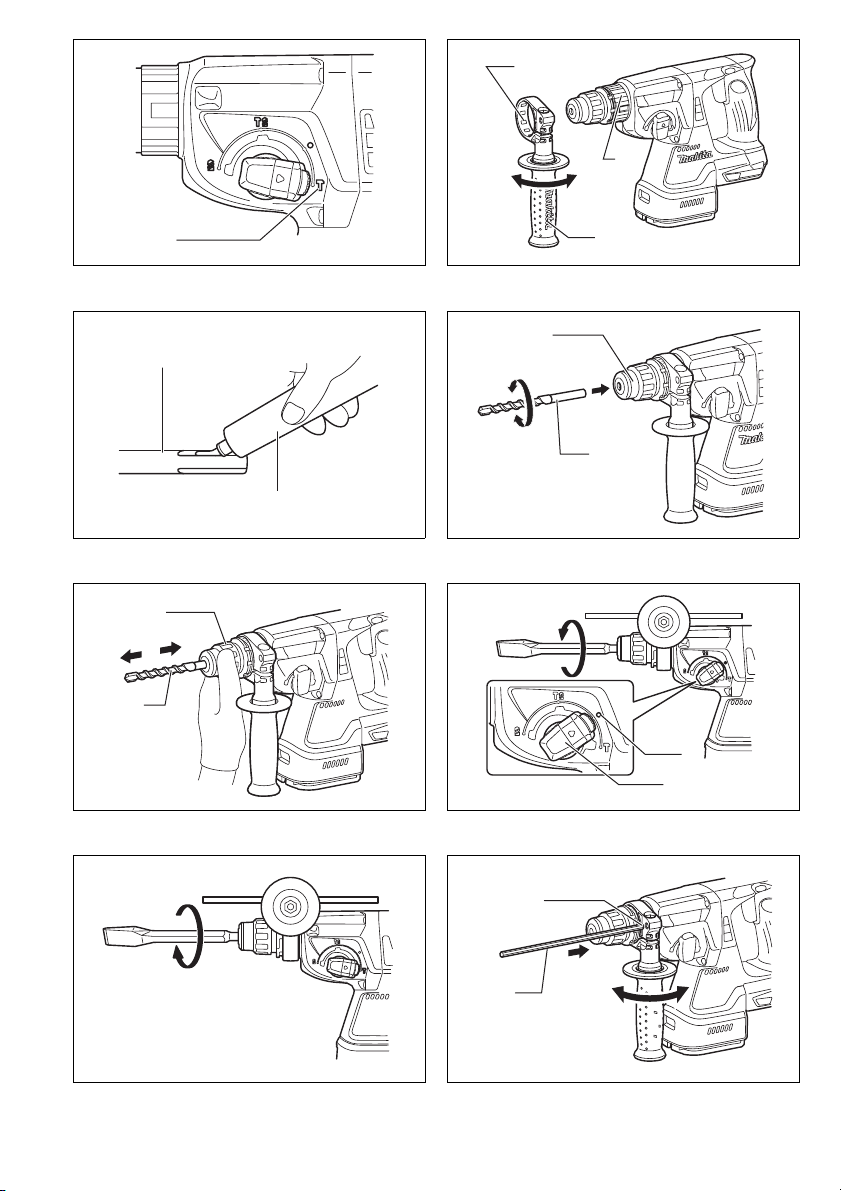
Side grip (auxiliary handle) (Fig. 10)
CAUTION:
• Always use the side grip to ensure operating safety.
Install the side grip so that the protrusion on the grip fit in
between the grooves in the tool barrel. Then tighten the
grip by turning clockwise at the desired position. It may
be swung 360° so as to be secured at any position.
Bit grease
Coat the bit shank head beforehand with a small amount
of bit grease (about 0.5 – 1 g). This chuck lubrication
assures smooth action and longer service life.
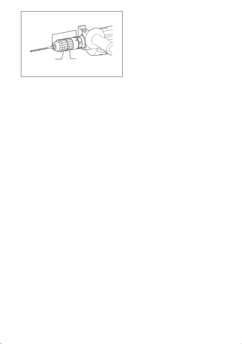
Installing or removing the bit
Clean the bit shank and apply bit grease before installing
the bit. (Fig. 11)
Insert the bit into the tool. Turn the bit and push it in until
it engages.
If the bit cannot be pushed in, remove the bit. Pull the
chuck cover down a couple of times. Then insert the bit
again. Turn the bit and push it in until it engages.
(Fig. 12)
After installing, always make sure that the bit is securely
held in place by trying to pull it out.
To remove the bit, pull the chuck cover down all the way
and pull the bit out. (Fig. 13)
Bit angle (when chipping, scaling or demolishing)
(Fig. 14 & 15)
The bit can be secured at the desired angle. To change
the bit angle, depress the lock button and rotate the
action mode changing knob to the
bit to the desired angle.
Depress the lock button and rotate the action mode
changing knob to the symbol. Then make sure that
the bit is securely held in place by turning it slightly.
O symbol. Turn the
8
Page 9

Depth gauge (Fig. 16)
006382
The depth gauge is convenient for drilling holes of uniform depth. Loosen the side grip and insert the depth
gauge into the hole in the side grip. Adjust the depth
gauge to the desired depth and tighten the side grip.
NOTE:
• The depth gauge cannot be used at the position where
the depth gauge strikes against the gear housing.
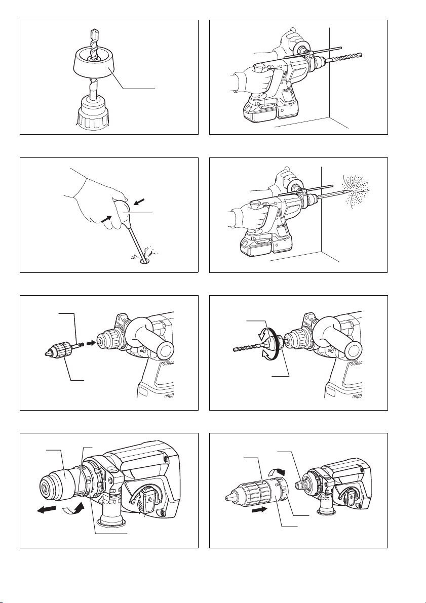
Dust cup (Fig. 17)
Use the dust cup to prevent dust from falling over the tool
and on yourself when performing overhead drilling operations. Attach the dust cup to the bit as shown in the figure. The size of bits which the dust cup can be attached
to is as follows.
Bit diameter
Dust cup 5 6 mm – 14.5 mm
Dust cup 9 12 mm – 16 mm
OPERATION
Hammer drilling operation (Fig. 18)
Set the action mode changing knob to the symbol.
Position the bit at the desired location for the hole, then
pull the switch trigger.
Do not force the tool. Light pressure gives best results.
Keep the tool in position and prevent it from slipping
away from the hole.
Do not apply more pressure when the hole becomes
clogged with chips or particles. Instead, run the tool at an
idle, then remove the bit partially from the hole. By
repeating this several times, the hole will be cleaned out
and normal drilling may be resumed.
CAUTION:
• There is a tremendous and sudden twisting force
exerted on the tool/bit at the time of hole breakthrough, when the hole becomes clogged with chips
and particles, or when striking reinforcing rods embedded in the concrete. Always use the side grip (auxiliary
handle) and firmly hold the tool by both side grip and
switch handle during operations. Failure to do so may
result in the loss of control of the tool and potentially
severe injury.
NOTE:
• Eccentricity in the bit rotation may occur while operating the tool with no load. The tool automatically centers
itself during operation. This does not affect the drilling
precision.
Blow-out bulb (optional accessory) (Fig. 19)
After drilling the hole, use the blow-out bulb to clean the
dust out of the hole.
Chipping/Scaling/Demolition (Fig. 20)
Set the action mode changing knob to the symbol.
Hold the tool firmly with both hands. Turn the tool on and
apply slight pressure on the tool so that the tool will not
bounce around, uncontrolled. Pressing very hard on the
tool will not increase the efficiency.
Drilling in wood or metal (Fig. 21 & 22)
Use the optional drill chuck assembly. When installing it,
refer to the section “Installing or removing the bit”.
Set the action mode changing knob so that the pointer
points to the
m symbol.
For Model DHR243 (Fig. 23, 24 & 25)
CAUTION:
• Never use “Rotation with hammering” when the drill
chuck assembly is installed on the tool. The drill chuck
assembly may be damaged. Also, the drill chuck will
come off when reversing the tool.
Use the quick change drill chuck as standard equipment.
When installing it, refer to the section “Changing the
quick change chuck for SDS-plus”.
Hold the ring and turn the sleeve counterclockwise to
open the chuck jaws. Place the bit in the chuck as far as
it will go. Hold the ring firmly and turn the sleeve clockwise to tighten the chuck. To remove the bit, hold the ring
and turn the sleeve counterclockwise.
Set the action mode changing knob to the m symbol.
You can drill up to 13 mm diameter in metal and up to
32 mm diameter in wood.
CAUTION:
• Never use “Rotation with hammering” when the quick
change drill chuck is installed on the tool. The quick
change drill chuck may be damaged.
Also, the drill chuck will come off when reversing the
tool.
• Pressing excessively on the tool will not speed up the
drilling. In fact, this excessive pressure will only serve
to damage the tip of your bit, decrease the tool performance and shorten the service life of the tool.
• There is a tremendous twisting force exerted on the
tool/bit at the time of hole breakthrough. Hold the tool
firmly and exert care when the bit begins to break
through the workpiece.
• A stuck bit can be removed simply by setting the
reversing switch to reverse rotation in order to back
out. However, the tool may back out abruptly if you do
not hold it firmly.
• Always secure small workpieces in a vise or similar
hold-down device.
MAINTENANCE
CAUTION:
• Always be sure that the tool is switched off and the battery cartridge is removed before attempting to perform
inspection or maintenance.
• Never use gasoline, benzine, thinner, alcohol or the
like. Discoloration, deformation or cracks may result.
To maintain product SAFETY and RELIABILITY, repairs,
carbon brush inspection and replacement, any other
maintenance or adjustment should be performed by
Makita Authorized Service Centers, always using Makita
replacement parts.
OPTIONAL ACCESSORIES
CAUTION:
• These accessories or attachments are recommended
for use with your Makita tool specified in this manual.
The use of any other accessories or attachments might
present a risk of injury to persons. Only use accessory
or attachment for its stated purpose.
9
Page 10

If you need any assistance for more details regarding
these accessories, ask your local Makita Service Center.
• SDS-Plus Carbide-tipped bits
• Bull point
• Cold chisel
• Scaling chisel
• Grooving chisel
• Drill chuck assembly
• Drill chuck S13
• Chuck adapter
• Chuck key S13
• Bit grease
• Side grip
• Depth gauge
• Blow-out bulb
• Dust cup
• Dust extractor attachment
• Safety goggles
• Plastic carrying case
• Keyless drill chuck
• Various type of Makita genuine batteries and chargers
NOTE:
• Some items in the list may be included in the tool package as standard accessories. They may differ from
country to country.
ENG905-1
Noise
The typical A-weighted noise level determined according
to EN60745:
Model DHR242
Sound pressure level (L
Sound power level (L
Uncertainty (K): 3 dB (A)
Model DHR243
Sound pressure level (L
Sound power level (L
Uncertainty (K): 3 dB (A)
Vibration
The vibration total value (tri-axial vector sum) determined
according to EN60745:
Wear ear protection
): 90 dB (A)
pA
): 101 dB (A)
WA
): 89 dB (A)
pA
): 100 dB (A)
WA
ENG900-1
Model DHR242
Work mode: hammer drilling into concrete
Vibration emission (a
Uncertainty (K): 1.5 m/s
Work mode: chiselling
Vibration emission (a
Uncertainty (K): 1.5 m/s
Work mode: drilling into metal
Vibration emission (
Uncertainty (K): 1.5 m/s
Model DHR243
Work mode: hammer drilling into concrete
Vibration emission (a
Uncertainty (K): 1.5 m/s
Work mode: chiselling
Vibration emission (a
Uncertainty (K): 1.5 m/s
h, HD
h, CHeq
a
h, D
h, HD
h, CHeq
): 13.5 m/s
2
2
): 3.5 m/s
2
): 13 m/s
2
2
Work mode: drilling into metal
a
Vibration emission (
Uncertainty (K): 1.5 m/s
): 2.5 m/s
h, D
2
): 10.5 m/s
2
2
): 11 m/s
2
or less
2
2
2
• The declared vibration emission value has been measured in accordance with the standard test method and
may be used for comparing one tool with another.
• The declared vibration emission value may also be
ENG901-1
used in a preliminary assessment of exposure.
WARNING:
• The vibration emission during actual use of the power
tool can differ from the declared emission value
depending on the ways in which the tool is used.
• Be sure to identify safety measures to protect the operator that are based on an estimation of exposure in the
actual conditions of use (taking account of all parts of
the operating cycle such as the times when the tool is
switched off and when it is running idle in addition to
the trigger time).
ENH101-15
For European countries only
EC Declaration of Conformity
We Makita Corporation as the responsible manufacturer declare that the following Makita machine(s):
Designation of Machine: Cordless Combination Hammer
Model No./ Type: DHR242, DHR243
are of series production and
Conforms to the following European Directives:
2006/42/EC
And are manufactured in accordance with the following
standards or standardised documents:
EN60745
The technical documentation is kept by our authorised
representative in Europe who is:
Makita International Europe Ltd.
Michigan Drive, Tongwell,
Milton Keynes, Bucks MK15 8JD, England
6.21.2011
Tomoyasu Kato
Director
Makita Corporation
3-11-8, Sumiyoshi-cho,
Anjo, Aichi, 446-8502, JAPAN
10
Page 11

NEDERLANDS (Originele instructies)
Verklaring van algemene gegevens
1 Rode indicator
2Knop
3 Accu
4 Stermarkering
5 Trekkerschakelaar
6 Omkeerschakelaar
7 Snelwisselkop voor SDS-plus
8 Streep op wisselmof
9 Wisselmof
10 As
11 Snelwisselboorkop
12 Ronddraaien met hameren
TECHNISCHE GEGEVENS
Model DHR242 DHR243
Capaciteiten
Beton ........................................................................................24 mm 24 mm
Hout ..........................................................................................13 mm 13 mm
Staal ..........................................................................................27 mm 27 mm
Toerental onbelast (min
Aantal slagen/minuut ...................................................................0– 4 700 0–4700
Totale lengte ................................................................................328mm 353 mm
Netto gewicht ...............................................................................3,3 kg 3,4 kg
Nominale spanning ......................................................................D.C. 18 V D.C. 18V
–1
) ...........................................................0 – 950 0 – 950
13 Vergrendelknop
14 Werkingsfunctie-keuzeknop
15 Alleen ronddraaien
16 Alleen hameren
17 Uitsteeksel
18 Groef
19 Losmaken
20 Vastzetten
21 Zijhandgreep
22 Boorschacht
23 Boorvet
24 Boor
25 Boorkopmof
O-symbool
26
27 Gat
28 Diepteaanslag
29 Stofvanger
30 Blaasbalgje
31 Boorkopadapter
32 Sleutelloze boorkop
33 Bus
34 Ring
• In verband met ononderbroken research en
ontwikkeling behouden wij ons het recht voor
bovenstaande technische gegevens te wijzigen zonder
voorafgaande kennisgeving.
• De technische gegevens de accu kunnen van land tot
land verschillen.
• Gewicht, inclusief accu, volgens de EPTA-procedure
01/2003
ENE043-1
Doeleinden van gebruik
Dit gereedschap is bedoeld voor hamerboren en boren in
baksteen, beton en steen, en ook voor beitelen.
Het gereedschap is ook geschikt voor boren zonder slag
in hout, metaal, keramisch materiaal en kunststof.
GEA010-1
Algemene veiligheidswaarschuwingen voor
elektrisch gereedschap
WAARSCHUWING! Lees alle veiligheidswaar-
schuwingen en alle instructies. Het niet volgen van de
waarschuwingen en instructies kan leiden tot elektrische
schokken, brand en/of ernstig letsel.
Bewaar alle waarschuwingen en instructies om in de
toekomst te kunnen raadplegen.
GEB046-2
VEILIGHEIDSWAARSCHUWINGEN VOOR
SNOERLOZE BOORHAMER
1. Draag gehoorbescherming. Blootstelling aan
harde geluiden kan leiden tot gehoorbeschadiging.
2. Gebruik de hulphandgrepen die bij het
gereedschap werden geleverd. Als u de controle
over het gereedschap verliest, kan dit leiden tot
ernstig persoonlijk letsel.
3. Houd elektrisch gereedschap vast aan het
geïsoleerde oppervlak van de handgrepen
wanneer u werkt op plaatsen waar het
slijpaccessoire met verborgen bedrading of zijn
eigen snoer in aanraking kan komen. Wanneer
het booraccessoire in aanraking komen met onder
spanning staande draden, zullen de nietgeïsoleerde metalen delen van het gereedschap
onder spanning komen te staan zodat de gebruiker
een elektrische schok kan krijgen.
4. Draag een veiligheidshelm, veiligheidsbril en/of
gezichtsbescherming. Een gewone bril of een
zonnebril is GEEN veiligheidsbril. Het wordt
tevens sterk aanbevolen een stofmasker en dik
gevoerde handschoenen te dragen.
5. Controleer dat het bit stevig op zijn plaats is
vastgezet voordat u het gereedschap gebruikt.
6. Bij normale bediening behoort het gereedschap
te trillen. De schroeven kunnen gemakkelijk
losraken, waardoor een defect of ongeluk kan
ontstaan. Controleer of de schroeven goed zijn
aangedraaid, alvorens het gereedschap te
gebruiken.
7. In koude weersomstandigheden of wanneer het
gereedschap gedurende een lange tijd niet is
gebruikt, laat u het gereedschap eerst opwarmen
door het onbelast te laten werken. Hierdoor zal
de smering worden verbeterd. Zonder degelijk
opwarmen, zal de hamerwerking moeilijk zijn.
8. Zorg er altijd voor dat u stevig staat.
Zorg ervoor dat er niemand zich onder u bevindt
wanneer u het gereedschap op een hoge plaats
gebruikt.
9. Houd het gereedschap met beide handen stevig
vast.
10. Houd uw handen uit de buurt van bewegende
delen.
29
Page 12

11. Laat het gereedschap niet ingeschakeld liggen.
Bedien het gereedschap alleen wanneer u het
vasthoudt.
12. Richt het gereedschap niet op iemand in de
buurt terwijl het is ingeschakeld. Het bit zou eruit
kunnen vliegen en iemand ernstig verwonden.
13. Raak het bit en onderdelen in de buurt van het
bit niet onmiddellijk na gebruik aan. Zij kunnen
bijzonder heet zijn en brandwonden op uw huid
veroorzaken.
14. Sommige materialen bevatten chemische stoffen
die giftig kunnen zijn. Neem de nodige
voorzorgsmaatregelen tegen inademing van stof
en contact met de huid. Volg de
veiligheidsinstructies van de leverancier van het
materiaal op.
BEWAAR DEZE VOORSCHRIFTEN.
WAARSCHUWING:
Laat u NIET misleiden door een vals gevoel van
comfort en bekendheid met het gereedschap (na
veelvuldig gebruik) en neem alle
veiligheidsvoorschriften van het betreffende
gereedschap altijd strikt in acht. VERKEERD
GEBRUIK of het niet naleven van de
veiligheidsvoorschriften in deze gebruiksaanwijzing
kan leiden tot ernstige verwondingen.
ENC007-7
BELANGRIJKE
VEILIGHEIDSVOORSCHRIFTEN VOOR ACCU
1. Lees alle voorschriften en waarschuwingen op
(1) de acculader, (2) de accu, en (3) het product
waarvoor de accu wordt gebruikt, aandachtig
door alvorens de accu in gebruik te nemen.
2. Neem de accu niet uit elkaar.
3. Als de gebruikstijd van een opgeladen accu
aanzienlijk korter is geworden, moet u het
gebruik ervan onmiddellijk stopzetten.
Voortgezet gebruik kan oververhitting,
brandwonden en zelfs een ontploffing
veroorzaken.
4. Als er elektrolyt in uw ogen is terechtgekomen,
spoel dan uw ogen met schoon water en roep
onmiddellijk de hulp van een dokter in. Elektrolyt
in de ogen kan blindheid veroorzaken.
5. Voorkom kortsluiting van de accu:
(1) Raak de accuklemmen nooit aan met een
geleidend materiaal.
(2) Bewaar de accu niet in een bak waarin
andere metalen voorwerpen zoals spijkers,
munten e.d. worden bewaard.
(3) Stel de accu niet bloot aan water of regen.
Kortsluiting van de accu kan oorzaak zijn van
een grote stroomafgifte, oververhitting,
brandwonden, en zelfs defecten.
6. Bewaar het gereedschap en de accu niet op
plaatsen waar de temperatuur kan oplopen tot
50°C of hoger.
7. Werp de accu nooit in het vuur, ook niet wanneer
hij zwaar beschadigd of volledig versleten is. De
accu kan namelijk ontploffen in het vuur.
8. Wees voorzichtig dat u de accu niet laat vallen
en hem niet blootstelt aan schokken of stoten.
9. Gebruik nooit een beschadigde accu.
BEWAAR DEZE VOORSCHRIFTEN.
Tips voor een maximale levensduur van de accu
1. Laad de accu op voordat hij volledig ontladen is.
Stop het gebruik van het gereedschap en laad de
accu op telkens wanneer u vaststelt dat het
vermogen van het gereedschap is afgenomen.
2. Laad een volledig opgeladen accu nooit opnieuw
op. Als u de accu te veel oplaadt, zal hij minder
lang meegaan.
3. Laad de accu op bij een kamertemperatuur
tussen 10°C en 40°C. Laat een warme accu
afkoelen alvorens hem op te laden.
4. Laad de accu tenminste eenmaal in zes
maanden op, als u het apparaat geruime tijd lang
niet gebruikt.
FUNCTIEBESCHRIJVING
LET OP:
• Zorg altijd dat het gereedschap is uitgeschakeld en de
accu is verwijderd, alvorens u enige controle of
afstelling aan het gereedschap uitvoert.
Aanbrengen en verwijderen van de accu (Fig. 1)
LET OP:
• Houd het gereedschap en de accu stevig vast
wanneer u de accu aanbrengt of verwijdert. Als u
het gereedschap en de accu niet stevig vasthoudt, zou
er iets uit uw handen kunnen glippen, met gevaar voor
schade aan het gereedschap of de accu en eventuele
verwonding.
• Schakel altijd het gereedschap uit voordat u de accu
aanbrengt of verwijdert.
• Om de accu te verwijderen, schuift u deze uit het
gereedschap los terwijl u de knop voorop de accu
ingedrukt houdt.
• Voor het aanbrengen van de accu plaatst u de tong van
de accu in de groef van de behuizing en schuift u de
accu op zijn plaats. Schuif de accu er altijd volledig in
totdat die op zijn plaats vastklikt. Wanneer de rode
indicator op de bovenkant van de knop nog zichtbaar
is, zit de accu niet volledig erin. Schuif hem volledig
erin totdat de rode indicator niet meer zichtbaar is. Als
u dit nalaat, zou de accu uit het gereedschap kunnen
vallen en uzelf of anderen kunnen verwonden.
• Druk de accu er niet met kracht in. Als de accu er niet
soepel in gaat, houdt u die waarschijnlijk in de
verkeerde stand.
Accubeveiligingssysteem (lithium-ionenaccu met
stermarkering) (Fig. 2)
Lithium-ionenaccu’s met een stermarkering zijn voorzien
van een beveiligingssysteem. Dat kan automatisch de
stroomtoevoer naar het gereedschap afsluiten om de
levensduur van de accu te verlengen.
Het gereedschap kan tijdens gebruik automatisch
stoppen wanneer het gereedschap en/of de accu aan
één van de volgende omstandigheden wordt
blootgesteld:
• Overbelasting:
Als het gereedschap wordt gebruikt op een manier die
een abnormaal hoge stroomsterkte vergt.
30
Page 13

In dat geval laat u de trekkerschakelaar van het
gereedschap los en verhelpt u de oorzaak van de
overbelasting. Vervolgens drukt u de trekkerschakelaar
weer in om het gereedschap te herstarten.
Als het gereedschap niet start, kan de accu oververhit
zijn. In dat geval laat u de accu even afkoelen voordat
u de trekkerschakelaar opnieuw indrukt.
• Onvoldoende accuspanning:
Als de resterende accuspanning onvoldoende is, zal
het gereedschap niet starten. In dat geval verwijdert u
de accu en laadt u die opnieuw op.
Werking van de schakelaar (Fig. 3)
LET OP:
• Alvorens u de accu in het gereedschap plaatst,
controleert u eerst of de schakelaar goed werkt en bij
loslaten automatisch naar de “OFF”-stand terugkeert.
Om het gereedschap te starten, drukt u enkel de
trekkerschakelaar in. De snelheid van het gereedschap
neemt toe, hoe verder u de trekkerschakelaar indrukt.
Laat de trekkerschakelaar los om te stoppen.
Werking omkeerschakelaar (Fig. 4)
Dit gereedschap heeft een omkeerschakelaar voor het
veranderen van de draairichting. Druk de
omkeerschakelaar in vanaf kant A voor rechtse,
kloksgewijze draairichting, of vanaf kant B voor linkse
draairichting.
Wanneer deze schakelaar in de neutrale stand staat, kan
de trekkerschakelaar niet worden ingedrukt.
LET OP:
• Controleer altijd de draairichting alvorens het
gereedschap te starten.
• Verander de stand van de omkeerschakelaar alleen
nadat het gereedschap volledig tot stilstand is
gekomen. Als u de draairichting verandert terwijl het
gereedschap nog draait, kan het gereedschap
beschadigd raken.
• Zet de omkeerschakelaar altijd in de neutrale stand
wanneer u het gereedschap niet gebruikt.
De snelwisselkop voor SDS-plus vervangen
Voor model DHR243
De snelwisselkop voor SDS-plus kan eenvoudig worden
vervangen door de snelwisselboorkop.
De snelwisselkop voor SDS-plus verwijderen (Fig. 5)
LET OP:
• Haal altijd de boor eruit voordat u de snelwisselkop
voor SDS-plus verwijdert.
Pak de wisselmof van de snelwisselkop voor SDS-plus
vast en draai deze in de richting van de pijl totdat de
streep op de wisselmof van het symbool is verplaatst
naar het symbool . Trek krachtig in de richting van de
pijl.
De snelwisselboorkop aanbrengen (Fig. 6)
Controleer of de streep op de snelwisselboorkop bij het
symbool staat. Pak de wisselmof van de
snelwisselboorkop vast en zet de streep bij het symbool
.
Zet de snelwisselboorkop op de as van het gereedschap.
Pak de wisselmof van de snelwisselboorkop en draai de
streep op de wisselmof naar het symbool totdat er
een duidelijke klik te horen is.
De werkingsfunctie kiezen
Ronddraaien met hameren (Fig. 7)
Voor boren in beton, metselwerk, enz., drukt u de
vergrendelknop in en draait u de werkingsfunctiekeuzeknop naar het symbool . Gebruik een boor met
een wolfraamcarbide punt.
Alleen ronddraaien (Fig. 8)
Voor boren in hout, metaal of kunststofmaterialen, drukt
u de vergrendelknop in en draait u de werkingsfunctiekeuzeknop naar het symbool m. Gebruik een spiraalboor
of houtboor.
Alleen hameren (Fig. 9)
Voor beitelen, bikken of sloopwerkzaamheden, drukt u
de vergrendelknop in en draait u de werkingsfunctiekeuzeknop naar het symbool . Gebruik een
puntbeitel, koudbeitel, bikbeitel, enz.
LET OP:
• Verstel de stand van de werkingsfunctie-keuzeknop
niet terwijl het gereedschap draait. Daardoor zal het
gereedschap worden beschadigd.
• Om snelle slijtage van het omschakelmechanisme te
voorkomen, zorgt u dat de werkingsfunctie-keuzeknop
altijd precies in een van de drie standen staat.
• Als u de knop van het symbool naar het symbool m
draait, is het mogelijk dat u de werkingsfunctiekeuzeknop niet verder dan het symbool kunt
draaien. In dat geval schakelt u het gereedschap
opnieuw in of draait u de boorkop met de hand naar het
symbool , en draait u vervolgens de
werkingsfunctie-keuzeknop verder. Als u de
werkingsfunctie-keuzeknop forceert, kan het
gereedschap worden beschadigd.
Koppelbegrenzer
De koppelbegrenzer treedt in werking wanneer de motor
een bepaald koppelniveau bereikt. De motor wordt dan
ontkoppeld van de uitgaande aandrijfas. Wanneer dit
gebeurt, zal de boor stoppen met draaien.
LET OP:
• Schakel het gereedschap onmiddellijk uit wanneer de
koppelbegrenzer in werking treedt. Hiermee helpt u
vroegtijdige slijtage van het gereedschap voorkomen.
• Gatenzagen mogen niet worden gebruikt met dit
gereedschap. Dergelijke zagen kunnen gemakkelijk
bekneld raken in het boorgat. Daardoor zou de
koppelbegrenzer al te vaak in werking treden.
INEENZETTEN
LET OP:
• Controleer altijd of het gereedschap is uitgeschakeld
en de accu is verwijderd alvorens enig werk aan het
gereedschap uit te voeren.
Zijhandgreep (hulphandgreep) (Fig. 10)
LET OP:
• Gebruik altijd de zijhandgreep om veilig te kunnen
werken.
Plaats de zijhandgreep zodanig op het gereedschap dat
de uitsteeksels van de zijhandgreep in de groeven van
het gereedschap passen. Draai daarna de zijhandgreep
vast door deze in de gewenste stand rechtsom te
draaien. De zijhandgreep kan 360° rondgedraaid worden
en in iedere gewenste stand worden vastgezet.
31
Page 14

Boorvet
006382
Voordat u de boor aanbrengt, smeert u een beetje
boorvet (ongeveer 0,5 tot 1 gram) op de kop van de
boorschacht. Met een ingevette boorkop zal het
gereedschap beter werken en langer meegaan.
Aanbrengen en verwijderen van de boor
Reinig de boorschacht en smeer er boorvet op alvorens
de boor te plaatsen. (Fig. 11)
Steek de boor in het gereedschap. Draai de boor en duw
deze naar binnen tot hij vergrendelt.
Als de boor er niet volledig in geduwd kan worden,
verwijdert u die boor dan. Trek eerst de boorkopmof
enkele malen omlaag. Steek vervolgens de boor
opnieuw in. Draai de boor en duw deze naar binnen tot
hij vergrendelt. (Fig. 12)
Controleer na het aanbrengen altijd of de boor stevig in
het gereedschap is bevestigd door te proberen deze eruit
te trekken.
Om de boor te verwijderen, trekt u de boorkopmof
helemaal omlaag en trekt u dan de boor eruit. (Fig. 13)
Boorhoek (bij beitelen, bikken of slopen)
(Fig. 14 en 15)
De boor kan in de gewenste hoek worden vastgezet. Om
de boorhoek te veranderen, drukt u de vergrendelknop in
en draait u de werkingsfunctie-keuzeknop naar het
O. Draai de boor in de gewenste hoek.
symbool
Druk de vergrendelknop in en draai de werkingsfunctiekeuzeknop naar het symbool . Controleer daarna of
de boor stevig op zijn plaats vastzit door deze iets te
verdraaien.
Diepteaanslag (Fig. 16)
De diepteaanslag is handig voor het boren van gaten van
gelijke diepte. Draai de zijhandgreep los en steek de
diepteaanslag in de opening in de zijhandgreep. Stel de
diepteaanslag af op de gewenste diepte en draai de
zijhandgreep weer vast.
OPMERKING:
• De diepteaanslag kan niet worden gebruikt in een
stand waarbij de diepteaanslag tegen het
aandrijvingshuis aan komt.
Stofvanger (Fig. 17)
Gebruik de stofvanger om te voorkomen dat er stof op
het gereedschap en op uzelf terechtkomt wanneer u
boven uw hoofd boort. Bevestig de stofvanger op de
boor zoals aangegeven in de afbeelding. De diameter
van de boren waaraan de stofvanger kan worden
bevestigd is als volgt.
Boordiameter
Stofvanger 5 6 mm – 14,5 mm
Stofvanger 9 12 mm – 16 mm
BEDIENING
Gebruik als boorhamer (Fig. 18)
Draai de werkingsfunctie-keuzeknop naar het symbool
.
Plaats de punt van de boor op de gewenste plaats waar
het boorgat moet komen en druk vervolgens de
trekkerschakelaar in.
Forceer het gereedschap niet. Een lichte druk geeft de
beste resultaten.
Houd het gereedschap stevig vast en zorg dat de boor
niet uit het gat wegglijdt.
Oefen geen grotere druk uit wanneer het boorgat
verstopt raakt met schilfertjes of boorgruis. Laat in zo’n
geval het gereedschap langzaam lopen en verwijder de
boor gedeeltelijk uit het boorgat. Wanneer dit
verschillende keren wordt herhaald, zal het boorgat
schoon worden en kunt u normaal verder boren.
LET OP:
• Op het moment dat het boorgat doorbreekt, het
boorgat verstopt raakt met schilfertjes of boorgruis, of
de boorhamer de bewapening in het beton raakt, wordt
er plotseling een enorme wringende kracht uitgeoefend
op het gereedschap/de boor. Gebruik altijd de
zijhandgreep (hulphandgreep) en houd het
gereedschap tijdens gebruik stevig vast aan zowel de
zijhandgreep als de schakelhandgreep. Als u dit niet
doet, kunt u de macht over het gereedschap verliezen
en mogelijk ernstig letsel veroorzaken.
OPMERKING:
• Wanneer het gereedschap onbelast wordt gebruikt,
kan de boor soms excentrisch draaien. Het
gereedschap centreert zichzelf automatisch tijdens het
gebruik. Dit heeft geen nadelige invloed op de
nauwkeurigheid van het boren.
Blaasbalgje (optioneel accessoire) (Fig. 19)
Gebruik na het boren het blaasbalgje om het stof uit het
boorgat te blazen.
Beitelen/bikken/slopen (Fig. 20)
Draai de werkingsfunctie-keuzeknop naar het symbool
.
Houd het gereedschap met beide handen stevig vast.
Schakel het gereedschap in en oefen er enige kracht op
uit zodat het gereedschap niet oncontroleerbaar in het
rond springt. Het gereedschap werkt niet efficiënter als u
grote druk op het gereedschap uitoefent.
Boren in hout of metaal (Fig. 21 en 22)
Gebruik de los verkrijgbare complete boorkop. Om deze
aan te brengen, volgt u de aanwijzingen onder
“Aanbrengen en verwijderen van de boor”.
Stel de werkingsfunctie-keuzeknop zo in dat de wijzer
naar het symbool
Voor model DHR243 (Fig. 23, 24 en 25)
LET OP:
• Gebruik nooit “Ronddraaien met hameren” wanneer de
complete boorkop op het gereedschap is aangebracht.
De complete boorkop kan daardoor worden
beschadigd. Bovendien zal de boorkop loskomen
wanneer de draairichting van het gereedschap wordt
omgekeerd.
Gebruik de snelwisselboorkop als standaarduitrusting.
Om deze aan te brengen, volgt u de aanwijzingen onder
“De snelwisselkop voor SDS-plus vervangen”.
Houd de ring op zijn plaats en draai de bus linksom om
de klauwen van de boorkop te openen. Steek de boor zo
ver mogelijk in de boorkop. Houd de ring stevig op zijn
plaats en draai de bus rechtsom om de klauwen van de
boorkop te sluiten. Om de boor te verwijderen, houdt u
de ring op zijn plaats en draait u de bus linksom.
Draai de werkingsfunctie-keuzeknop naar het symbool m.
U kunt gaten tot een diameter van 13 mm in metaal
boren en tot een diameter van 32 mm in hout.
m wijst.
32
Page 15

LET OP:
• Gebruik nooit “Ronddraaien met hameren” wanneer de
snelwisselboorkop op het gereedschap is aangebracht.
De snelwisselboorkop kan daardoor worden
beschadigd.
Bovendien zal de boorkop loskomen wanneer de
draairichting van het gereedschap wordt omgekeerd.
• Het boren zal niet sneller verlopen als u hard op het
gereedschap drukt. In feite zal dergelijk hard drukken
alleen maar leiden tot beschadiging van de boor,
mindere prestaties van het gereedschap en verkorting
van de levensduur van het gereedschap.
• Op het moment dat het boorgat doorbreekt wordt een
enorme wringende kracht uitgeoefend op het
gereedschap/de boor. Houd het gereedschap stevig
vast en let vooral goed op wanneer de boor door het
werkstuk heen breekt.
• Een vastgelopen boorkop kan eenvoudig verwijderd
worden door de draairichting te veranderen met de
omkeerschakelaar, om zo de boorkop los te halen.
Houd het gereedschap daarbij wel stevig vast, want er
is kans op een plotselinge terugslag.
• Zet kleinere werkstukken altijd vast in een bankschroef
of dergelijke veiligheidsklem.
ONDERHOUD
LET OP:
• Zorg er altijd voor dat het gereedschap is
uitgeschakeld en de accu is verwijderd, voordat u
enige inspectie of onderhoud uitvoert.
• Gebruik nooit benzine, wasbenzine, verdunner,
alcohol, enz. Dat kan leiden tot verkleuren, vervormen
of barsten.
Om de VEILIGHEID en BETROUWBAARHEID van het
gereedschap te verzekeren, dienen alle reparaties,
inspectie en vervanging van koolborstels, en alle andere
onderhoudswerkzaamheden of afstellingen te worden
uitgevoerd door een erkend Makita servicecentrum, en
dit uitsluitend met gebruik van originele Makita
vervangingsonderdelen.
OPTIONELE ACCESSOIRES
LET OP:
• Deze accessoires en hulpstukken zijn aanbevolen voor
gebruik met uw Makita gereedschap zoals
voorgeschreven in deze handleiding. Het gebruik van
enige andere accessoires of hulpstukken kan gevaar
voor lichamelijk letsel opleveren. Gebruik accessoires
en hulpstukken alleen voor hun voorgeschreven
toepassing.
Als u advies nodig hebt omtrent deze accessoires,
raadpleegt u dan uw plaatselijke Makita servicecentrum.
• SDS-Plus boren met hardmetalen carbide punt
• Puntbeitel
• Koudbeitel
• Bikbeitel
• Sleuvenbeitel
• Complete boorkop
• Boorkop S13
• Boorkopadapter
• Boorkopsleutel S13
• Boorvet
• Zijhandgreep
• Diepteaanslag
• Blaasbalgje
• Stofvanger
• Stofafzuig-aansluitstuk
• Veiligheidsbril
• Plastic draagkoffer
• Sleutelloze boorkop
• Diverse typen originele Makita accu’s en acculaders
OPMERKING:
• Sommige van de onderdelen in deze lijst kunnen
bijgeleverd zijn als standaard-accessoires. Deze
accessoires kunnen per land verschillend zijn.
33
Page 16

ENG905-1
Geluidsniveau
De typisch, A-gewogen geluidsniveaus vastgesteld
volgens EN60745:
Model DHR242
Geluidsdrukniveau (L
Geluidsenergie-niveau (L
Onnauwkeurigheid (K): 3 dB (A)
Model DHR243
Geluidsdrukniveau (L
Geluidsenergie-niveau (L
Onnauwkeurigheid (K): 3 dB (A)
Draag oorbeschermers
Trilling
De totaalwaarde van de trillingen (triaxiale vectorsom)
vastgesteld volgens EN60745:
): 90 dB (A)
pA
): 101 dB (A)
WA
): 89 dB (A)
pA
): 100 dB (A)
WA
ENG900-1
Model DHR242
Toepassing: klopboren in beton
Trillingsemissie (a
Onnauwkeurigheid (K): 1,5 m/s
Toepassing: beitelen
Trillingsemissie (a
Onnauwkeurigheid (K): 1,5 m/s
Toepassing: boren in metaal
Trillingsemissie (
Onnauwkeurigheid (K): 1,5 m/s
Model DHR243
Toepassing: klopboren in beton
Trillingsemissie (a
Onnauwkeurigheid (K): 1,5 m/s
Toepassing: beitelen
Trillingsemissie (a
Onnauwkeurigheid (K): 1,5 m/s
Toepassing: boren in metaal
Trillingsemissie (
Onnauwkeurigheid (K): 1,5 m/s
• De opgegeven trillingsemissiewaarde is gemeten
volgens de standaardtestmethode en kan worden
gebruikt om dit gereedschap te vergelijken met andere
gereedschappen.
• De opgegeven trillingsemissiewaarde kan ook worden
gebruikt voor een beoordeling vooraf van de
): 13,5 m/s
h, HD
h, CHeq
a
): 3,5 m/s
h, D
): 13 m/s
h, HD
h, CHeq
a
): 2,5 m/s2 of lager
h, D
2
): 10,5 m/s
2
2
2
2
2
): 11 m/s
2
2
2
2
2
ENG901-1
blootstelling.
WAARSCHUWING:
• De trillingsemissie tijdens het gebruik van het elektrisch
gereedschap in de praktijk kan verschillen van de
opgegeven trillingsemissiewaarde afhankelijk van de
manier waarop het gereedschap wordt gebruikt.
• Zorg ervoor dat veiligheidsmaatregelen worden
getroffen ter bescherming van de operator die zijn
gebaseerd op een schatting van de blootstelling onder
praktijkomstandigheden (rekening houdend met alle
fasen van de bedrijfscyclus, zoals de tijdsduur
gedurende welke het gereedschap is uitgeschakeld en
stationair draait, naast de ingeschakelde tijdsduur).
Alleen voor Europese landen
ENH101-15
EU-Verklaring van Conformiteit
Wij, Makita Corporation, als de verantwoordelijke
fabrikant, verklaren dat de volgende Makitamachine(s):
Aanduiding van de machine: Snoerloze combinatiehamer
Modelnr./Type: DHR242, DHR243
in serie zijn geproduceerd en
Voldoen aan de volgende Europese richtlijnen:
2006/42/EC
En zijn gefabriceerd in overeenstemming met de
volgende normen of genormaliseerde documenten:
EN60745
De technische documentatie wordt bewaard door onze
erkende vertegenwoordiger in Europa, te weten:
Makita International Europe Ltd.
Michigan Drive, Tongwell,
Milton Keynes, Bucks MK15 8JD, Engeland
6.21.2011
Tomoyasu Kato
Directeur
Makita Corporation
3-11-8, Sumiyoshi-cho,
Anjo, Aichi, 446-8502, JAPAN
34
 Loading...