

Page 1
T
ECHNICAL INFORMATION
Models No.
Description
BHR241
Cordless Combination Hammer
CONCEPT AND MAIN APPLICATIONS
The cordless version of HR2470 has been launched
with D-handle for operator's comfort.
This new product is available in the following variations.
Model No.
BHR241RFE
BHR241RF
BHR241Z
The variations for USA, Canada, Mexico and Panama are as follows.
Model No.
BHR241
BHR241Z
Battery
Type Quantity
BL1830
No No No
Battery
Type Quantity
BL1830
No No No
2
1
---
2
---
Charger
DC18RA
Charger
DC18RA
carrying case
carrying case
Plastic
Yes
Yes
Plastic
Yes
PRODUCT
P 1/ 14
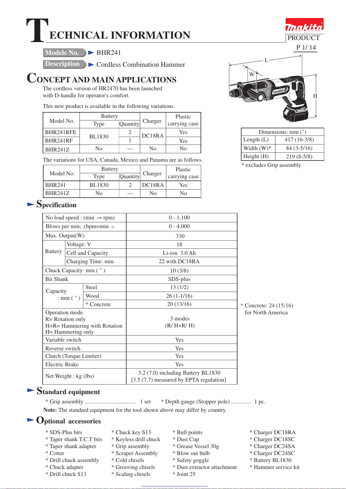
L
W
Dimensions: mm (")
Length (L)
Width (W)*
Height (H)
* excludes Grip assembly
417 (16-3/8)
84 (3-5/16)
219 (8-5/8)
H
Specification
No load speed : (min -1= rpm)
Blows per min, :(bpm=min
Max. Output(W)
Voltage: V
Battery
Chuck Capacity: mm ( " )
Bit Shank
Capacity
: mm ( " )
Operation mode
R= Rotation only
H+R= Hammering with Rotation
H= Hammering only
Variable switch
Reverse switch
Clutch (Torque Limiter)
Electric Brake
Net Weight : kg (lbs)
Cell and Capacity
Charging Time: min.
Steel
Wood
* Concrete
0 - 1,100
-1)
3.2 (7.0) including Battery BL1830
[3.5 (7.7) measured by EPTA regulation]
0 - 4,000
330
18
Li-ion 3.0 Ah
22 with DC18RA
10 (3/8)
SDS-plus
13 (1/2)
26 (1-1/16)
20 (13/16)
3 modes
(R/ H+R/ H)
Yes
Yes
Yes
Yes
* Concrete: 24 (15/16)
for North America
Standard equipment
* Grip assembly ................................... 1 set * Depth gauge (Stopper pole) .............. 1 pc.
Note: The standard equipment for the tool shown above may differ by country.
Optional accessories
* SDS-Plus bits
* Taper shank T.C.T bits
* Taper shank adapter
* Cotter
* Drill chuck assembly
* Chuck adapter
* Drill chuck S13
* Chuck key S13
* Keyless drill chuck
* Grip assembly
* Scraper Assembly
* Cold chisels
* Grooving chisels
* Scaling chisels
* Bull points
* Dust Cup
* Grease Vessel 30g
* Blow out bulb
* Safety goggle
* Dust extractor attachment
* Joint 25
* Charger DC18RA
* Charger DC18SC
* Charger DC24SA
* Charger DC24SC
* Battery BL1830
* Hammer service kit
Page 2
P 2/ 14
[1] NECESSARY REPAIRING TOOLS
CAUTION: Remove the battery and the bit from the machine for safety before
repair/ maintenance in accordance with the instruction manual!
Repair
DescriptionCode No.
1R003 Retaining ring S pliers SR-2 Removing / Installing Ring spring 19
Removing Ring spring 29
Removing Helical gear 25 from Cam shaft
Disassemble Oil seal 25 and Needle bearing complete from Gear housing
complete
Disassemble Ball bearing 608ZZ from Cam shaft
Installing Helical gear 25 to Cam shaft
Installing Oil seal 25 to Gear housing complete
Installing Oil seal 25 to Gear housing complete
Installing Needle bearing complete to Gear housing complete
Holding Tool holder complete
1R004 Retaining ring S pliers ST-2N
1R022
1R023
Bearing plate for Arbor press
Pipe ring (for Arbor press)
1R033
1R032
Bearing setting plate 10.2
Bearing setting plate 8.2
1R038 Armature holder 32 set for vise
1R164 Ring spring setting tool A
1R165 Ring spring setting tool B
1R212
Tip for Retaining ring pliers Attaching to 1R003 for removing Ring spring 19
1R232 Pipe 30
1R252 Round bar for Arbor 30-100
1R269 Bearing extractor
1R281 Round bar for Arbor 7-50
Removing Striker from Tool holder complete
Removing Ring 8 from Cam shaft
Removing / Installing Retaining ring S-7 from / to Cam shaft
Removing / Installing Ring spring 29 from / to Tool holder complete
1R291 Retaining ring S and R pliers
1R306 Ring spring removing jig
Use for
[2] LUBRICATION
Apply the following grease to protect parts and product from unusual abrasion.
* Makita grease R No.00 to the portions marked with black triangle
* Molybdenum disulfide lubricant to the portions marked with gray triangle
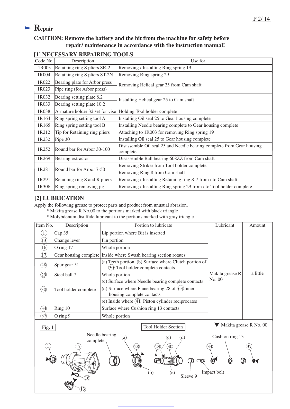
Fig. 1
Item No. Description Portion to lubricate Lubricant Amount
a little
1
(a) (c) (d)
(e)
16
17 28
Needle bearing
complete
29 30
13
34 37
Sleeve 9
Impact bolt
Cushion ring 13
(b)
Cap 35
O ring 17
1
16
Change lever
13
Gear housing complete
Spur gear 51
17
28
Steel ball 7
29
Tool holder complete
30
Lip portion where Bit is inserted
Whole portion
Pin portion
Inside where Swash bearing section rotates
(a) Teeth portion, (b) Surface where Clutch portion of
30 Tool holder complete contacts
Whole portion
(c) Surface where Needle bearing complete contacts
(d) Surface where Plane bearing 28 of 63 Inner
housing complete contacts
(e) Inside where 41 Piston cylinder reciprocates
Ring 10
34
O ring 9
Surface where Cushion ring 13 contacts
Whole portion
37
Tool Holder Section
Makita grease R No. 00
Makita grease R
No. 00
Page 3
[2] LUBRICATION (cont.)
Repair
P 3/ 14
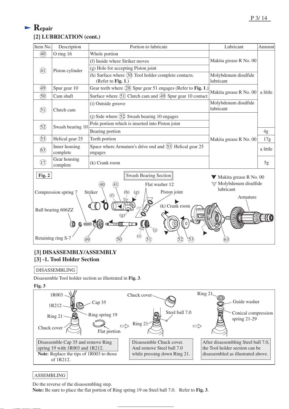
Fig. 2
Item No. Description Portion to lubricate Lubricant Amount
Striker
Ball bearing 606ZZ
Compression spring 7
Disassemble Tool holder section as illustrated in Fig. 3.
Retaining ring S-7
Piston joint
Armature
Flat washer 12
Swash Bearing Section
40
41
51
52 53
63
(f)
(g)
(h)
(g)
(k) Crank room
(i)
(j)
50
49
51
52
53
63
17
40
41
Clutch cam
Bearing portion
(k) Crank room
4g
17g
Swash bearing 10
Helical gear 25
Gear housing
complete
Inner housing
complete
O ring 16
Piston cylinder
Whole portion
Makita grease R No. 00
Makita grease R No. 00
Makita grease R No. 00
Molybdenum disulfide
lubricant
Molybdenum disulfide
lubricant
Molybdenum disulfide
lubricant
Makita grease R No. 00
a little
a little
5g
Pole portion which is inserted into Piston joint
49 Spur gear 10 Gear teeth where 28 Spur gear 51 engages (Refer to Fig. 1.)
Teeth portion
Space where Armature's drive end and 53 Helical gear 25
engages
(f) Inside where Striker moves
(g) Hole for accepting Piston joint
(h) Surface where 30 Tool holder complete contacts.
(Refer to Fig. 1.)
(i) Outside groove
(j) Side where 52 Swash bearing 10 engages
50 Cam shaft Surface where 51 Clutch cam and 49 Spur gear 10 contact
[3] DISASSEMBLY/ASSEMBLY
[3] -1. Tool Holder Section
DISASSEMBLING
Ring 21
Ring 21
Guide washer
Conical compression
spring 21-29
Cap 35
Steel ball 7.0
Chuck cover
Ring spring 19
Chuck cover
1R003
1R212
Disassemble Cap 35 and remove Ring
spring 19 with 1R003 and 1R212.
Note: Replace the tips of 1R003 to those
of 1R212.
Ring 21
Disassemble Chuck cover.
And remove Steel ball 7.0
while pressing down Ring 21.
After disassembling Steel ball 7.0,
the Tool holder section can be
disassembled as illustrated above.
Fig. 3
ASSEMBLING
Do the reverse of the disassembling step.
Note: Be sure to place the flat portion of Ring spring 19 on Steel ball 7.0. Refer to Fig. 3.
Flat portion
Page 4
Repair
P 4/ 14
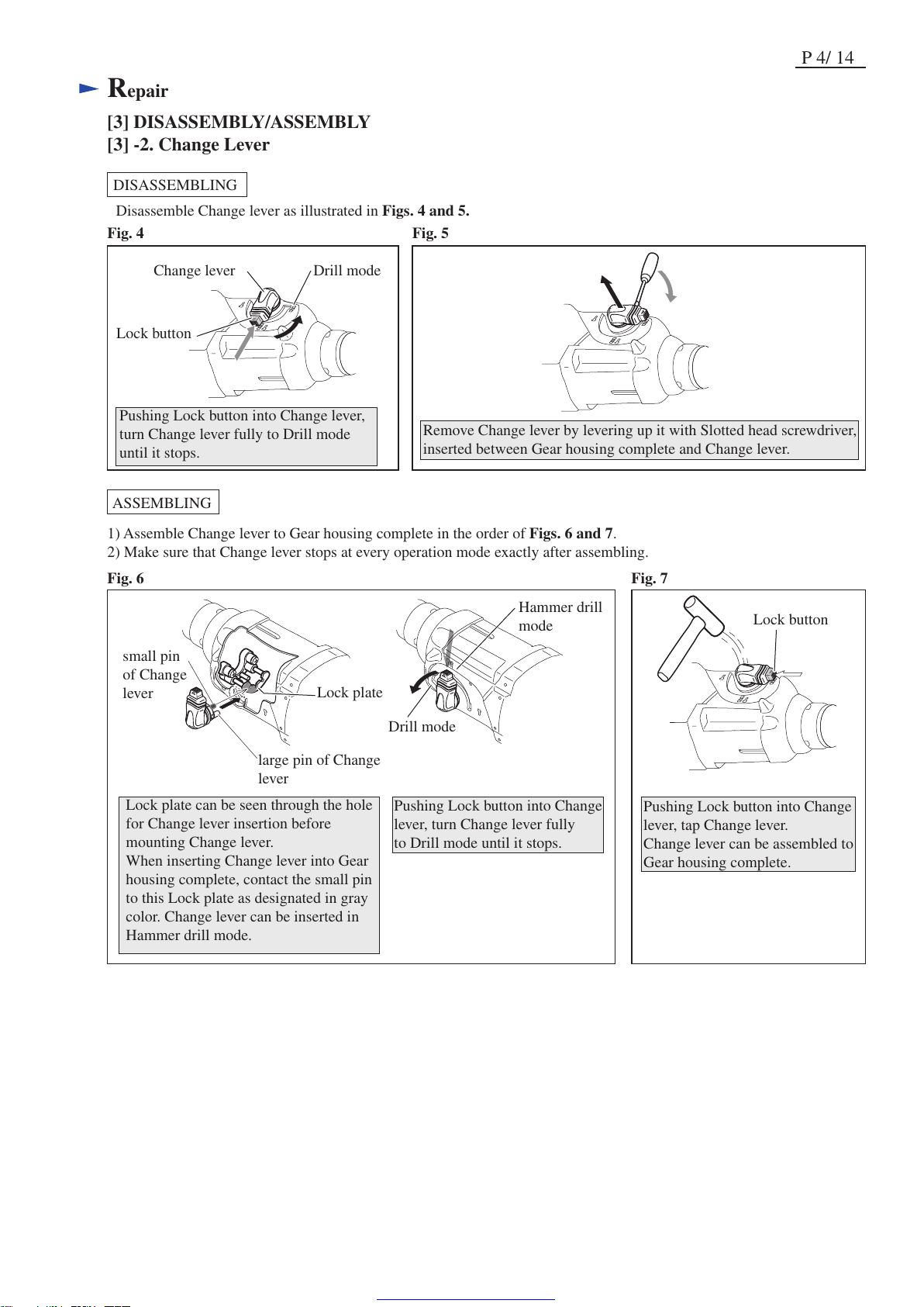
[3] DISASSEMBLY/ASSEMBLY
[3] -2. Change Lever
DISASSEMBLING
ASSEMBLING
Change lever Drill mode
Lock button
Pushing Lock button into Change lever,
turn Change lever fully to Drill mode
until it stops.
Remove Change lever by levering up it with Slotted head screwdriver,
inserted between Gear housing complete and Change lever.
Fig. 4 Fig. 5
Fig. 6 Fig. 7
Disassemble Change lever as illustrated in Figs. 4 and 5.
1) Assemble Change lever to Gear housing complete in the order of Figs. 6 and 7.
2) Make sure that Change lever stops at every operation mode exactly after assembling.
Lock plate
Drill mode
Hammer drill
mode
large pin of Change
lever
small pin
of Change
lever
Lock plate can be seen through the hole
for Change lever insertion before
mounting Change lever.
When inserting Change lever into Gear
housing complete, contact the small pin
to this Lock plate as designated in gray
color. Change lever can be inserted in
Hammer drill mode.
Pushing Lock button into Change
lever, turn Change lever fully
to Drill mode until it stops.
Pushing Lock button into Change
lever, tap Change lever.
Change lever can be assembled to
Gear housing complete.
Lock button
Page 5
Repair
P 5/ 14
bearing room of
Gear housing complete
4x40 Tapping screws (4 pcs.)
Gear housing
complete
Holder cap cover Motor housing
complete
Ball bearing 6000DDW
of Armature (behind the Fan)
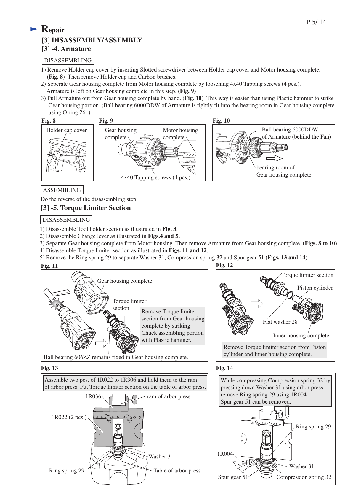
[3] DISASSEMBLY/ASSEMBLY
[3] -4. Armature
1) Remove Holder cap cover by inserting Slotted screwdriver between Holder cap cover and Motor housing complete.
(Fig. 8) Then remove Holder cap and Carbon brushes.
2) Seperate Gear housing complete from Motor housing complete by loosening 4x40 Tapping screws (4 pcs.).
Armature is left on Gear housing complete in this step. (Fig. 9)
3) Pull Armature out from Gear housing complete by hand. (Fig. 10) This way is easier than using Plastic hammer to strike
Gear housing portion. (Ball bearing 6000DDW of Armature is tightly fit into the bearing room in Gear housing complete
using O ring 26. )
Do the reverse of the disassembling step.
DISASSEMBLING
ASSEMBLING
Fig. 10Fig. 9Fig. 8
DISASSEMBLING
Fig. 11
Fig. 12
1) Disassemble Tool holder section as illustrated in Fig. 3.
2) Disassemble Change lever as illustrated in Figs.4 and 5.
3) Separate Gear housing complete from Motor housing. Then remove Armature from Gear housing complete. (Figs. 8 to 10)
4) Disassemble Torque limiter section as illustrated in Figs. 11 and 12.
5) Remove the Ring spring 29 to separate Washer 31, Compression spring 32 and Spur gear 51 (Figs. 13 and 14)
[3] -5. Torque Limiter Section
Remove Torque limiter section from Piston
cylinder and Inner housing complete.
Remove Torque limiter
section from Gear housing
complete by striking
Chuck assembling portion
with Plastic hammer.
Flat washer 28
Piston cylinder
Inner housing complete
Torque limiter section
Gear housing complete
Torque limiter
section
Ball bearing 606ZZ remains fixed in Gear housing complete.
Assemble two pcs. of 1R022 to 1R306 and hold them to the ram
of arbor press. Put Torque limiter section on the table of arbor press.
While compressing Compression spring 32 by
pressing down Washer 31 using arbor press,
remove Ring spring 29 using 1R004.
Spur gear 51 can be removed.
Washer 31
Washer 31
Ring spring 29
Compression spring 32
Ring spring 29
1R004
Table of arbor press
Fig. 13 Fig. 14
1R022 (2 pcs.)
1R036 ram of arbor press
Spur gear 51
Page 6

Repair
P 6/ 14
[3] DISASSEMBLY/ASSEMBLY
[3] -5. Torque Limiter Section (cont.)
ASSEMBLING
Do the reverse of disassembling steps.
Note: Do not forget to assemble Flat washer 28 between Torque limiter section and Inner housing complete. Refer to Fig. 12.
[3] DISASSEMBLY/ASSEMBLY
[3] -6. Needle Bearing Complete and Oil Seal 25
DISASSEMBLING
Applying 1R252, press it with Arbor press.
Needle bearing complete is removed
together with Oil seal 25 from Gear
housing complete.
1R252
1R252
Oil seal 25
Needle bearing
complete
Fig. 16
Fig. 15
1) Disassemble Torque limiter section and Inner housing complete from Gear housing complete.
See Disassembly of [3] -5. Torque Limiter Section.
2) Insert Inner housing complete into Gear housing complete. (Fig. 15)
3) Remove Needle bearing complete and Oil seal 25. (Fig. 16)
Inner housing complete
Gear housing complete
As the side for joining to Motor
housing is not flat, Gear housing
complete can not stand vertically
without support.
Therefore, insert Inner housing
complete into Gear housing
complete as a support.
ASSEMBLING
Fig. 20
Fig. 19
1) Assemble Oil seal 25 to Gear housing complete in the order of Figs. 17 and 18.
2) Assemble Needle bearing complete as illustrated in Figs. 19 and 20.
1R164
1R164
1R164
outer diameter: 30mm
outer diameter: 34mm
1R232
Oil seal 25
With 1R232 and arbor press, insert Oil seal 25 until it stops.
Oil seal 25 is not yet inserted completely in this step,
because the outer diameter of 1R232 is bigger than that of
Oil seal setting hole.
The initial position of Oil seal 25
Oil seal 25
The diameter of Oil seal 25 setting
hole is less than 36mm.
outer diameter: 36mm
back side
Gear housing complete
belly side
Needle bearing complete
Press Needle bearing with
arbor press and the outer
diameter 34mm end
surface of 1R164 until
Needle bearing complete
stops.
Fig. 17 Fig. 18
Face the flat portion of Needle bearing complete to
the belly side of Gear housing complete.
Needle bearing complete
flat portion
Press Oil seal 25 to the initial position with arbor press
and the outer diameter 34mm end surface of 1R164.
Page 7

Repair
P 7/ 14
DISASSEMBLI NG
1) Referring to "[3] -5. Torque Limiter Section", disassemble Ring spring 29, Washer 31, Compression spring 32
and Spur gear 51 from Tool holder complete. Refer to Figs. 11 to 14.
2) Holding Gear housing complete in vise and 1R038, Tap Ring spring 28 in Tool holder complete as illustrated in Figs. 21
and 22.
3) Remove Ring spring 28 from Tool holder complete and disassemble Impact bolt section. (Figs. 23 to 24)
Ring spring 28
Ring spring 28 can be pulled off from Tool holder
complete when completely removed from the
groove.
Disassemble Impact bolt
section by striking Tool
holder complete against
workbench.
Note: Be sure to replace Ring spring 28
when assembling Tool holder section.
Fig. 23
Fig. 24
Tool holder
complete
Sleeve 9
Impact bolt
Ring 10
Cushion ring 13
O ring case
Impact bolt section
[3] DISASSEMBLY/ASSEMBLY
[3] -7. Impact Bolt Section
Fig. 22
Fig. 21
end of Ring spring 28 Ring spring 28
When the end of Ring spring
28 is in the hole of Tool holder
complete, slide the end to the
blind side using a slotted
screwdriver.
Ring spring 28
1R038
Vise
Tap Ring spring 28 from
the two holes alternately
to push downward.
Tool holder
complete
ASSEMBLING
Fig. 25 Fig. 26 Fig. 27
Fig. 28
Tool holder
complete
1) Referring to Figs. 25, 26 and 27 assemble the Impact bolt section to Tool holder complete as illustrated in Fig. 28.
O Ring 9
O ring 9
O ring case
Note: Make sure O ring 9
is mounted to O ring
case in advance.
Note: Do not put the end of the ring spring 28 into
the two holes on Tool holder complete.
end of
Ring spring 28
hole
Correct
Wrong
Ring 10
Sleeve 9 Impact bolt
O ring case Ring spring 28
Cushion ring 13
15.5mm20mm
Note: This end has to be inserted
into Sleeve 9.
Incorrect assembling causes
trouble in hammering.
Impact bolt
Impact Bolt Section
assembled in Tool holder
complete
Page 8

[3] DISASSEMBLY/ASSEMBLY
[3] -7. Impact Bolt Section (cont.)
DISASSEMBLING
ASSEMBLING
Fig. 29
Note: Use an extra Piston cylinder as a jig. Never use Piston cylinder that is to be
assembled to the machine.
2) Push Ring spring 28 with Piston cylinder until it fits to the inner groove of Tool holder complete. (Fig. 29)
1) Disassemble Tool holder section as illustrated in Fig. 3.
2) Disassemble Change lever as illustrated in Figs. 4 and 5.
3) Separate Gear housing complete from Motor housing complete. And then, remove Armature from Gear housing complete.
(Refer to Figs. 8 to 10.)
4) Remove Stop ring E-4, Flat washer 5 and Compression spring 6 from pin of Inner housing complete. (Fig. 30)
5) Remove two M4x12 Hex socket bolts that fasten Bearing retainer to Inner housing complete. (Fig. 31)
[3] -8. Swash Bearing Section
Flat washer 5
Stop ring E-4
Compression spring 6
Change plate
Pin of Inner housing complete
M4x12 Hex socket
head bolt (2 pcs.)
Fig. 30 Fig. 31
Repair
P 8/ 14
Piston cylinder
as a repairing jig
Piston cylinder
as a repairing jig
Tool holder
complete
Ring spring 28
Inner groove of
Tool holder complete
Ring spring 28
O ring case
Page 9

[3] DISASSEMBLY/ASSEMBLY
[3] -8. Swash Bearing Section (cont.)
DISASSEMBLING
Fig. 32 Fig. 33
6) Move Piston cylinder to the rear dead center position (Fig. 32).
7) Remove Swash bearing section from Inner housing by pulling in the direction of the arrow. Then, remove Change plate
from the groove of Clutch cam. (Fig. 33).
Piston
cylinder
Swash bearing section
Piston cylinder
in the rear dead center position
Swash bearing section Inner housing complete
Change plate
Change plate
Clutch cam
Repair
P 9/ 14
8) Remove Ball bearing 606ZZ from Gear housing complete using the removed Swash bearing section as a jig as follows;
* Insert Cam shaft of Swash bearing section into the Ball bearing again.
* Tilt the Ball bearing a little bit by moving Swash bearing section as illustrated to left in Fig. 34.
* Ball bearing 606ZZ can now be removed by lightly tapping the edge of Gear housing complete with plastic
hammer as illustrated to right in Fig. 34.
Fig. 34
Swash bearing section
used as a jig
Ball bearing 606ZZ
Gear housing
complete
9) Remove Ring 8 using 1R022, 1R023, 1R281 and arbor press as illustrated in Fig. 35.
10) Remove Ball bearing 608ZZ using 1R269. Flat washer 8 and Bearing retainer can now be removed by hand. (Fig. 36)
Fig. 36Fig. 35
Ring 8
Ball bearing 608ZZ
Ball bearing
608ZZ
1R269
Ring 8
1R023
1R281
Bearing retainer
Flat washer 8
1R022
1R022
Page 10

[3] DISASSEMBLY/ASSEMBLY
[3] -8. Swash Bearing Section (cont.)
DISASSEMBLING
ASSEMBLING
1R032 1R033
Fig. 39
Swash
bearing 10
Helical gear 26
Retaining ring S-7
Compression spring 7
Spur gear 10
Cam shaft
Cam shaft
Clutch cam
1) Assemble Swash bearing section using 1R032, 1R033, 1R291 and arbor press as illustrated in Fig. 39.
Note: Be sure to put Flat washer 8 in place, or else Bearing retainer will be clamped between Ball bearing 608ZZ
and Helical gear 26.
Repair
P 10/ 14
11) Remove Helical gear 26 using 1R022, 1R023 and 1R281.
as illustrated to left in Fig. 37. Swash bearing 10 and Clutch cam can now be removed by hand (right in Fig. 37).
12) Remove Retaining ring S-7 using 1R291 (left in Fig. 38). Compression spring 7 and Spur gear 10 can now be removed
by hand. (right in Fig. 38).
Fig. 38
Fig. 37
Swash
bearing 10
Clutch cam
Retaining
ring S-7
Compression
spring 7
Spur gear 10
Cam shaft
Helical gear 26
1R023
1R281
1R022
1R291
Ring 8
Flat washer 8
Ball bearing
608ZZ
Bearing retainer
Page 11

[[3] DISASSEMBLY/ASSEMBLY
[3] -8. Swash Bearing Section (cont.)
Repair
ASSEMBLING
P 11/ 14
4) Move Piston cylinder to the rear dead center position. (Fig. 42)
5) Insert the pole of Swash bearing 10 into the hole of Piston joint as illustrated in Fig. 43.
6) Insert Ring 8 (the end of Swash bearing section) into Inner housing complete. (Fig. 44)
7) Fitting the tip of Change plate in the groove on Clutch cam, insert Change plate over the pins of Inner housing complete.
(Fig. 45)
Note: Ball bearing 608ZZ of Swash bearing section is not yet inserted into Inner housing complete in this step.
Fig. 44
Fig. 45
Fig. 42 Fig. 43
Piston cylinder at
rear dead center
position
Front Rear
Piston cylinder
Tilt Swash bearing 10 to insert the pole.
hole of Piston joint
tip of Clutch cam
Swash bearing section Ring 8
Clutch cam
groove
Inner housing complete pins of Inner housing complete
Ball bearing
608ZZ
Change plate
Piston joint
hole for the pole of
Swash bearing 10
Flat
washer 12
Flat
washer 12
Fig. 40 Fig. 41
2) Assemble Piston joint and two Flat washers 12 to Piston cylinder as illustrated in Fig. 40.
Note: Do not forget to apply Makita grease R No.00. Refer to Fig. 2.
3) Insert Piston cylinder into Inner housing complete. (Fig. 41).
Flat washer 12
Flat washer 12
Piston joint
Piston cylinder
Inner housing
Correct Wrong
pole of Swash
bearing 10
Ring 8
Ball bearing 608ZZ
M4x12 Hex socket head bolt ( 2 pcs.)
(with threadlocker coated)
Note: If reusing M4x12 hex.
socket head bolts, be sure
to apply ThreeBond 1321B
or 1342, or Loctite 242
to the threads before
fastening.
Stop ring E-4
Upper pin of
Inner housing complete
Flat washer 5 Compression spring 5
8) Insert Ball bearing 608ZZ of Swash bearing section into Inner housing complete, and fasten Swash bearing section to
Inner housing complete with two M4x12 hex socket head bolts. Then, put Compression spring 6 and Flat washer 5
through the upper pin of Inner housing complete, and secure them with Stop ring E-4 (Fig. 46)
Fig. 46
Ball bearing 608ZZ Ring 8
Page 12

Repair
[3] DISASSEMBLY/ASSEMBLY
[3]-9. F/R change lever, Wave washer, Cushion and Rubber pin 5 in Housing set
ASSEMBLING
Refer to Fig. 47.
Fig. 47
Fit the protrusion of Switch into Oval hole of F/R
change lever and assemble them to Housing L.
protrusion of
Switch
oval hole of
F/R change
lever
Wave washer 15
Do not forget to put Wave
washer 15 in place for
holding Ball bearing
607DDW on the commutator
end of Armature.
P 12/ 14
Housing set (L)
Battery housing set (L)
Terminal
Pass Pin 1.5 through Rubber pin 5.
And then, assemble them to Battery
housing set (L) as illustrated right.
Assemble Cushion to Battery
housing set (L) at the rear side of
Terminal.as illustrated above.
Pin 1.5
Rubber pin 5
Page 13

P 13/ 14
Maintenance program
It is recommended to replace the following parts shown below and apply lubricant to the specific parts designated in
Figs.2 and 3 when replacing Carbon brushes.
1 Cap 35
29 Steel
ball 7.0
40 O ring 16
Circuit diagram
Fig. D-1
Color index of lead wires' sheath
Black
Red
Blue
Yellow
Housing (L)
Side
Housing (R)
Side
Switch
35 Cushion
ring 13
37 O ring 9
Housing (L)
Side
Housing (R)
Side
38 Ring spring
28
Brush holder (L)
Yoke unit
Brush holder (R)
Heat sink
Housing (L)
Side
Terminal
Housing (R)
Side
Tape for
binding
Lead wires
FET
Page 14

Wiring diagram
Fig. D-2
Connecting terminal
Housing set (L)
P 14/ 14
Switch
Bend Connecting terminal to Housing set (L) side as
illustrated above.
Switch
Put the extra portion
of Lead wires in this
area.
Fix the Brush holder’s Lead wires
(red and black) with Lead wire holder.
Yoke unit
Heat sink
FET
Brush holder
Rib A
Route all of the FET lead wires
on the right side of Rib A.
Terminal
Fix the FET Lead wires
with Lead wire holder.
 Loading...