

Makita DF030D, DF030DW, DF030DWEW, DF030DWE Technical Information
PRODUCT
P 1/ 4
T
ECHNICAL INFORMATION
10.8
1.3
115
0 - 1,300
6.35 (1/4) Hex
0 - 350
High
Low
Li-ion
Models No.
Description
CONCEPT AND MAIN APPLICATIONS
Specification
Standard equipment
Optional accessories
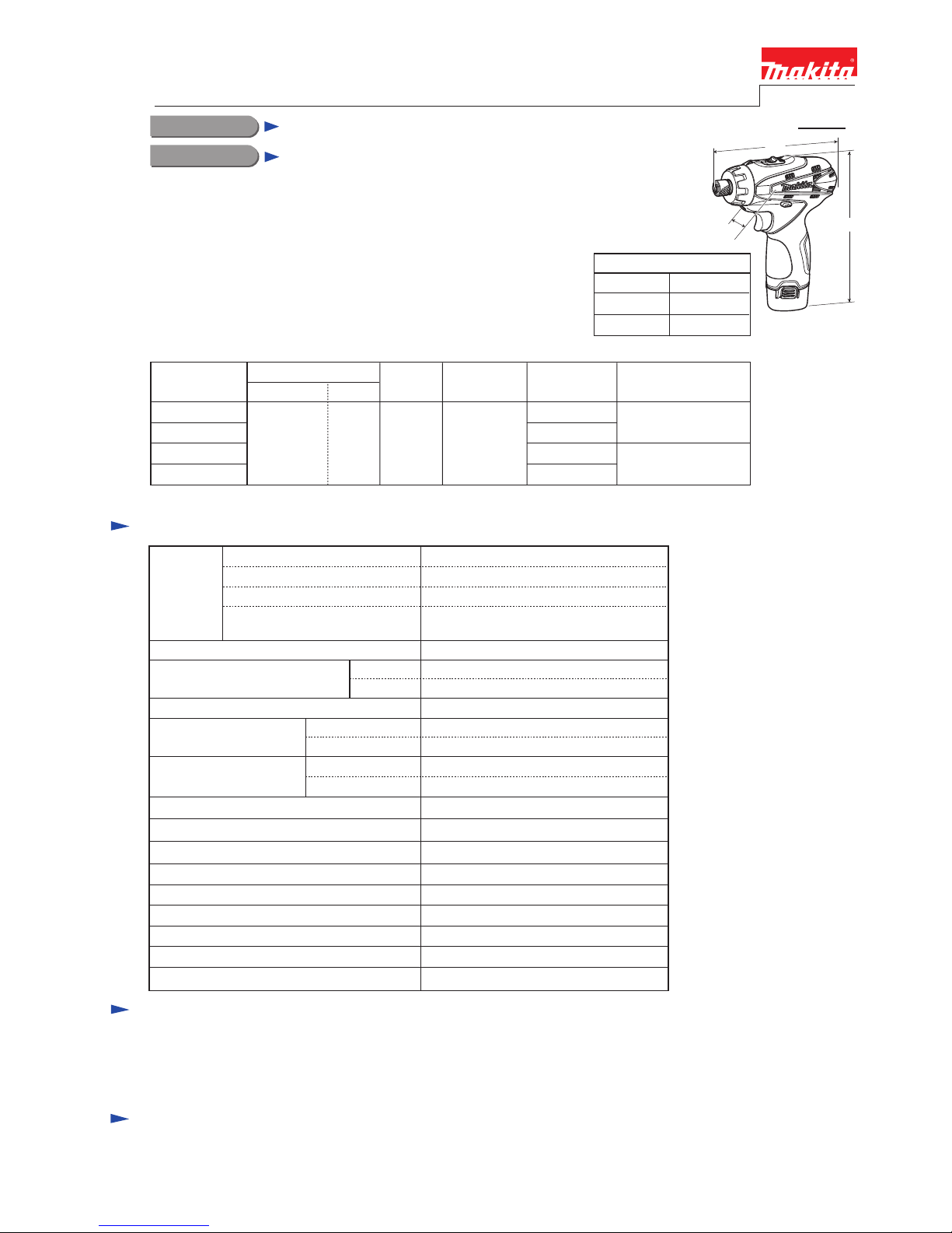
DF030D (FD01*)
10.8V Cordless Driver Drill
Dimensions: mm (")
Width (W)
Height (H)
Length (L) 157 (6-3/16)
53 (2-1/16)
183 (7-1/4)
No load speed: min-1 = rpm
Max. output: W
Battery
18 stages + drill modeTorque adjustment
Type of cell
Voltage: V
Capacity: Ah
Driving shank: mm (")
14 (120)
Max. fastening torque:
N.m (in.lbs)
Capacities: mm (")
0.5 - 3.5 (4 - 30)Clutch torque setting: N.m (in.lbs)
Steel
Wood
Soft joint
24 (210)
Hard joint
10 (3/8)
21 (13/16)
Driver bits, Socket bits, Hex shank drill bits for wood, Hex shank drill bits for steel, Bit piece,
Drill chuck, Charger DC10WA, Battery BL1013
Model DF030D is a 10.8V cordless driver drill compact and lightweight
for easy handling, but featuring 2-speed gear selection with variable speed
in each range for a wide range of applications.
Uses new 10.8V Li-ion battery of stick type as a power unit.
The models also includes the accessories listed below in "Standard equipment".
L
H
W
Yes
Yes
0.88 (1.9)
Reverse switch
LED job light
22 (200)Lock torque: N.m (in.lbs)
Yes
Yes
Yes
Electric brake
Variable speed control by trigger
Mechanical 2-speed
Net weight [with battery BL1013]: kg (lbs)
Note: The standard equipment for the tool shown above may differ by country.
Phillips bit 2-50 (double-end) ........ 1 pc (for countries using M-type spindle)
Phillips bit 2-45 (double-end) ........ 1 pc (for countries using N-type spindle)
Holster ............................................ 1 pc
This product is available in the following variations.
DF030D
DF030DW
DC10WA
Model No.
type quantity
Charger
2
BL1013
(Li-ion 1.3Ah)
Battery
Makita-blue
white
DF030DWE
DF030DWEW
Makita-blue
white
Housing
color
50
with DC10WA
Charging time (approx.): min.
Yes
Plastic
carrying case
Offered to
USA, Canada
Mexico, Panama
All countries except
the four listed above
* Model number for North and Central American
countries except Mexico and Guam
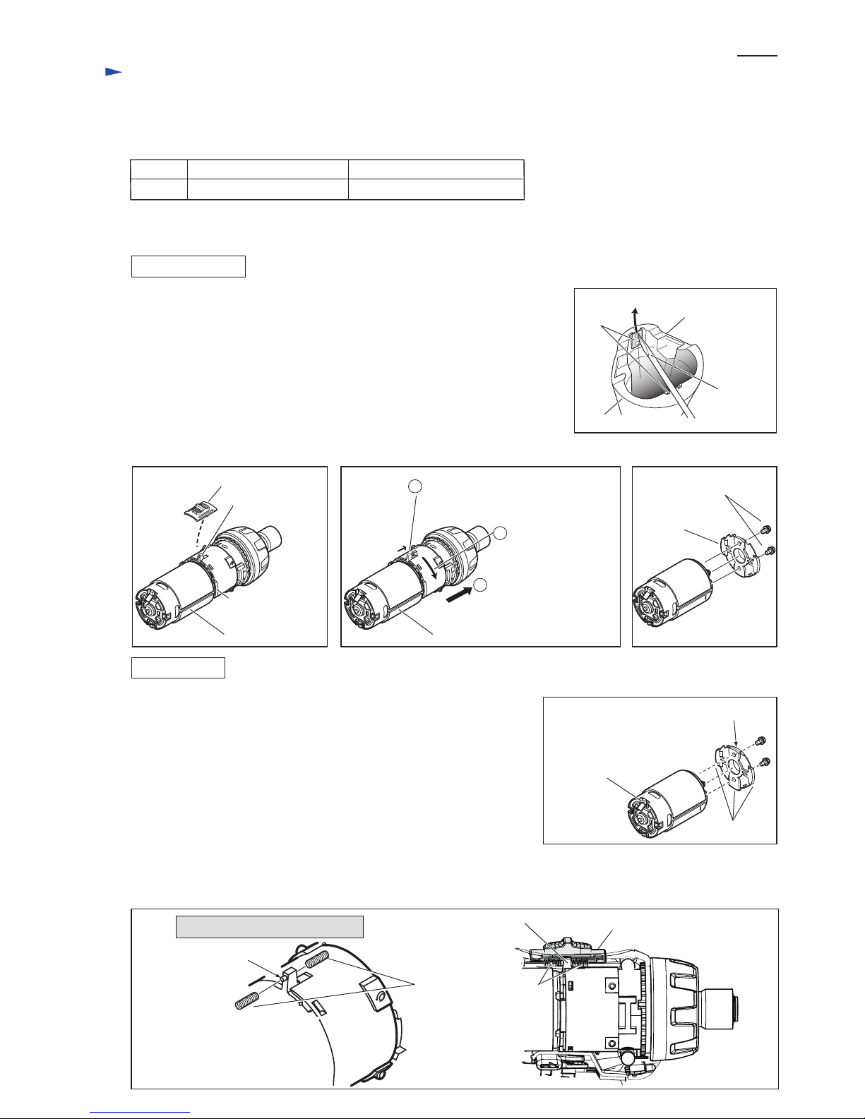
1) Remove two Set plates with which Handles (L) and (R) are assembled to one
another as follows:
Insert a small slotted screwdriver through the punched hole of Set plate and
move Set plate in the direction of the arrow using the screwdriver. (Fig.1)
2) Remove Housing (R) from Housing (L) by loosening six Bind PT3x6 tapping
screws.
3) Remove Speed change lever assembly from Gear assembly. (Fig. 2)
4) Remove DC motor from Gear assembly as illustrated in Fig. 3
5) Separate DC motor from Bracket by loosening two M3x6 Pan head screws.
(Fig. 4)
1) Fix Motor bracket to DC motor with two M3x6 Pan head screws.
Note: Align the red marking on DC motor with non-convex portion of
Motor bracket. (Fig. 5)
2) Fix Gear assembly to DC motor with bracket and turn Gear assembly
clockwise.
Note: Align the change lever of Gear assembly with the red marking on
DC motor. (Fig. 3)
3) Fix Speed change lever assembly to the change lever of Gear assembly as
illustrated in Fig. 2.
Note: Set the change lever of Gear assembly in place between two
Compression springs 4 on the reverse side of Speed change lever
assembly, and insert the emboss of the change lever into one of
Compression spring 4. (Fig. 6)
Repair
P 2/ 4
[2] DISASSEMBLY/ASSEMBLY
[3]-1. DC Motor, Gear Assembly, Speed Change Lever Assembly
Fig. 2 Fig. 4Fig. 3
DISASSEMBLING
ASSEMBLING
[1] NECESSARY REPAIRING TOOLS
CAUTION: Remove the bit and the battery from the machine for safety before
repair/ maintenance in accordance with the instruction manual!
DescriptionCode No. Use for
1R291 Removing/ Installing Bit sleeve
Fig. 1
Handle (R)
Handle (L)
small slotted
screwdriver
Set plate
(2pcs.)
Retaining ring S and R pliers
Speed change lever assembly
convex portion of
Motor bracket
change lever of
Gear assembly
change lever of
Gear assembly
Emboss of change lever
of Gear assembly
DC motor
Turn Gear assembly
counterclockwise.
Pull out Gear assembly
from DC motor with
Bracket.
DC motor
Motor bracket
M3x6 Pan head screws
(2pcs.)
1
Shift the change lever of Gear
assembly to the high speed position.
2
3
Fig. 5
Fig. 6
non-convex portion
Compression spring 4
Speed change lever assembly
red marking on
terminal of positive
pole
convex portions
Viewed from the upper position
 Loading...