

Page 1
T
ECHNICAL INFORMATION
PRODUCT
P 1/ 15
Models No.
Description
BTW074, BTW104
Cordless Impact Wrench
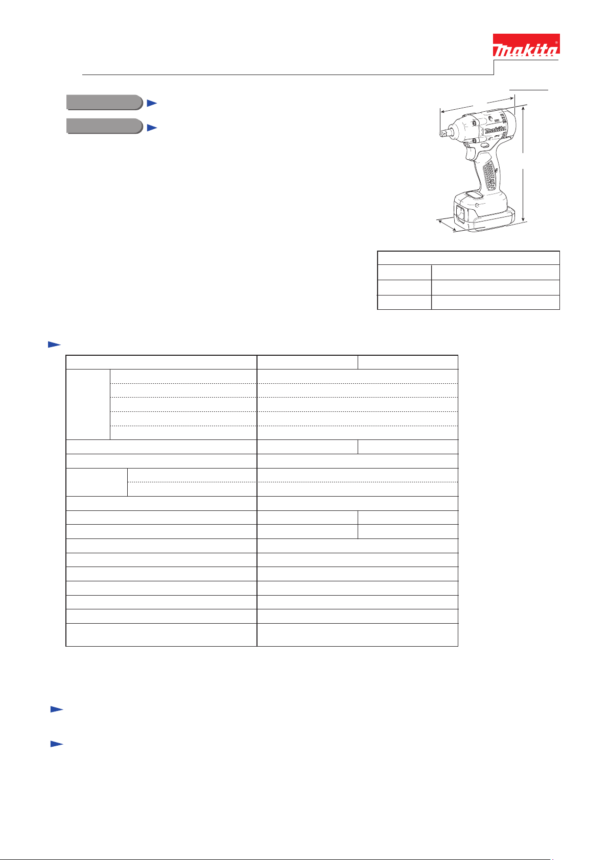
CONCEPT AND MAIN APPLICATIONS
These cordless impact wrenches for manufacturing industry as
the successors of BTW072 series models.
Their main features are:
• Extra compact design with a short overall length of 144mm (5-5/8")*
• Powered by our new 14.4V Li-ion batteries with battery fuel gauge:
BL1415NA (1.5Ah)/ BL1415NP (1.5Ah)/
BL1430A (3.0Ah)/ BL1430AP (3.0Ah)
• Automatic impact stop system to avoid under-tightening and
over-tightening
• Torque stabilization system to stabilize the torque of each fastening
• Automatic battery shut-off system to avoid incomplete fastenings
Specification
Model No.
Cell
Voltage: V
Battery
Max output (W)
Driving shank
Capacities
Impacts per min.: min.
No load speed: min.
Max. fastening torque: N.m [kgf·cm] (in.lbs)
Battery fuel gauge*
Automatic battery shut-off system
Electric brake
LED job light
Variable speed control by trigger
Reverse switch
Weight according to
EPTA-Procedure 01/2003*
*4 The fastening torque at 3 seconds after seating, when fastening M10 (grade 10.9) high tensile bolt.
*5 The fastening torque at 3 seconds after seating, when fastening M12 (grade 10.9) high tensile bolt.
*6 located on battery BL1415NA/ BL1415NAP/ BL1430A/ BL1430AP, not on the tool body
*7 with battery
Capacity: Ah
Energy capacity: Wh 22/ 44
Charging time (approx.): min.
Standard bolt
High tensile bolt
ˉ¹=ipm
ˉ¹=rpm
6
7: kg (lbs)
BTW074 BTW104
15/ 22 with DC18RC
140 150
9.5mm (3/8") Square drive
M5 - M12 (3/16 - 1/2")
M5 - M10 (3/16 - 3/8")
0 - 2,500 0 - 2,700
65 [660] (575)*
1
W
(The image above is Model BTW074.)
Dimensions: mm (")
Length (L)
Width (W)
Height (H)
*1 149mm (5-7/8”) for Anti-wobble anvil version
*2 with 1.5Ah Li-ion battery BL1415NA
*3 with 3.0Ah Li-ion battery of BL1430A
Li-ion
14.4
1.5/ 3.0
0 - 3,500
4 95 [970] (841)*5
Yes
Yes
Yes
Yes
Yes
Yes
1.1/ 1.3
(2.4/ 2.9)
144 (5-5/8)*
74 (2-15/16)
216 (8-1/2)
L
H
1
*1/ 234 (9-1/4)*2
Standard equipment
No
Optional accessories
Li-ion Battery BL1415NA
Li-ion Battery BL1415NAP
Li-ion Battery BL1430A
Li-ion Battery BL1430AP
Battery protector
Charger DC18SD
Charger DC24SC
Automotive charger DC18SE
Fast charger DC18RA (for USA, Canada, Guam, Panama, Mexico, Colombia)
Fast charger DC18RC (for all countries except the countries above)
Protectors (blue/ white/ red)
Automatic refreshing adapter ADP03
Page 2
P 2/ 15
Repair
CAUTION: Repair the machine in accordance with “Instruction manual” or “Safety instructions”.
[1] NECESSARY REPAIRING TOOLS
Code No. Description Use for
1R004 Retaining Ring S Pliers disassembling / assembling Ring spring 7
1R045 Gear extractor disassembling / assembling Hammer section
1R222
1R288
[2] LUBRICATION
Apply Makita grease FA No.2 to the following portions designated with the black triangle to protect parts and product
from unusual abrasion.
Socket Adapter
Screwdriver magnetizer removing Steel ball 5.6 from Spindle
securing Ring spring 7
Item No. Description
Anvil
14
Steel ball 3.5 (24 pcs.) Whole portion
16
Spindle
20
Steel ball 5.6 (2 pcs.)
25
Fig. 1
Ring spring 7
Hammer case
Drum portion which is accepted by Needle bearing 1412 mounted in
Hammer case complete
(a) Tip portion which is inserted into 14 Anvil
(b) in the hole where Spur gear 16 engages with Armature’s gear
Whole portion
14
16
Hammer
Washer 24
Compression spring 26
Cup washer 14
(a)
20
(b)
AmountPortion to lubricate
a little
a little
a little
approx. 2 g
a little
Internal gear 39
Internal gear case
Yoke unit
29
25
Spur gear 16
(2pcs.)
Page 3
Repair
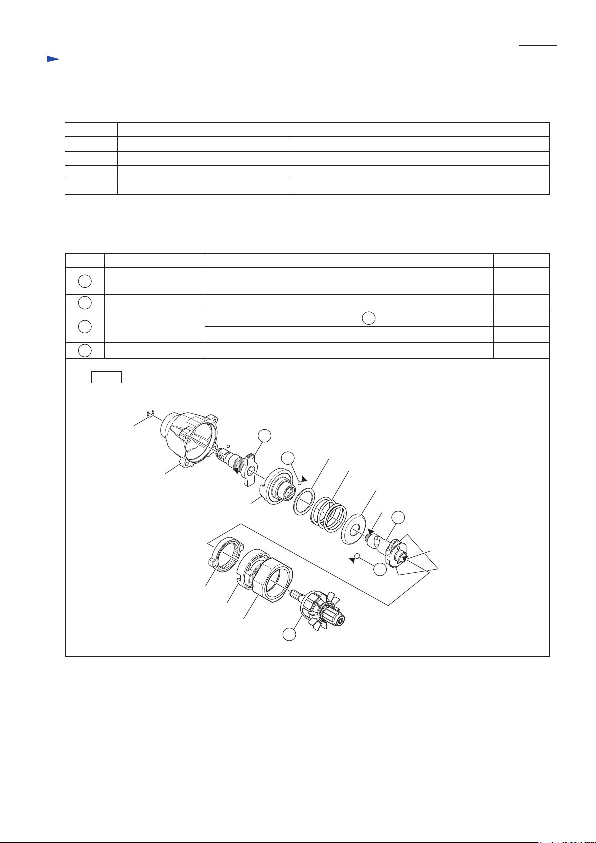
[3] DISASSEMBLY/ASSEMBLY
[3] -1. Note for Assembly/Disassembly
The models can be distinguished depending on the max. fastening torque. See Fig. 2.
Fig. 2
Model No.Max. fastening torque Distinctive Parts
ø39
Hammer B
Compression spring
(orange)
65 N.m
BTW073
BTW074
P 3/ 15
ID plate
(white)
ID plate
(red)
95 N.m
BTW103
BTW104
BTD063: Cover complete
(white)
BTD064: Switch plate complete
(white)
Hammer C
Compression spring
(green)
BTD103: Cover complete
(red)
BTD104: Switch plate complete
(red)
When repairing the products, be sure to assemble Hammer, Compression spring and Switch plate complete or
Cover complete as shown in Fig.2.
Page 4
P 4/ 15
Repair
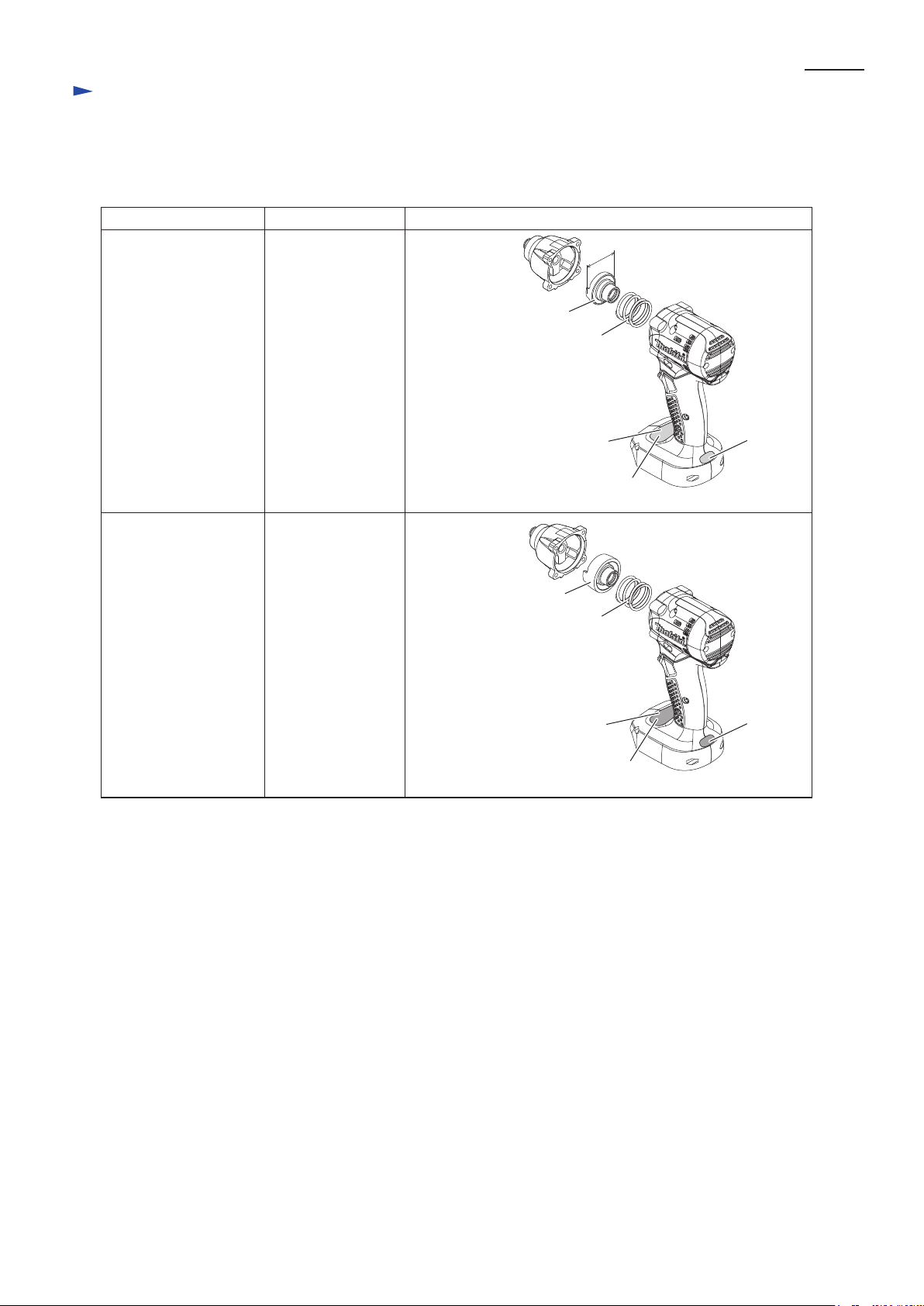
[3] DISASSEMBLY/ASSEMBLY
[3] -2. Armature
DISASSEMBLING
(1) Remove Armature section from Housing set as drawn in Fig. 3, and remove Brush holder from Armature in Fig. 4.
Fig. 3
1. Loosen four M4x22 Pan head screws and separate
Hammer case complete from Housing set.
Hammer case complete
M4x22
Pan head screw
Hammer case
(4 pcs.)
complete
3. Loosen seven M3x20 Pan head screws and
separate Housing set (R) from Housing set (L).
M3x20
Housing set (R)
Pan head screw
(7 pcs.)
2. Loosen two M3x12 Pan head screws and
separate Rear cover from Housing set.
Rear cover
M3x12
Pan head screw
4. Take out Brush holder and Motor section
(Armature and Yoke unit) together with
Internal gear case from Housing set (L).
Motor section
Brush holder
Internal gear case
Housing set (L)
Fig. 4
1. Shift the tail of Torsion spring
from the top of Carbon brush to
the notch of Brush holder.
Then, Carbon brush is free from
the pressure of Torsion spring.
Tail of
Torsion Spring
Carbon
Brush
Notch
Torsion
Spring
Tail of
Torsion spring
Carbon
Brush
Notch
2. Take out Carbon brushes.
Then, disassemble
Armature and Yoke unit
from Brush holder.
Carbon
Brush
Yoke unit
Carbon brush
Armature
Brush holder
Page 5
Repair
[3] DISASSEMBLY/ASSEMBLY
[3] -2. Armature (cont.)
DISASSEMBLING
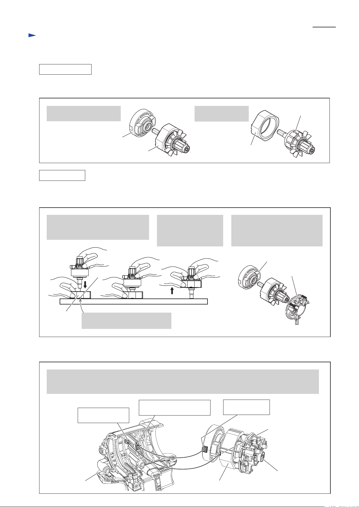
(1) Remove Armature as drawn in Fig. 5.
Fig. 5
P 5/ 15
1. Remove Internal gear case
from Motor section.
Internal gear case
Motor section
ASSEMBLING
(1) Insert Armature into Yoke unit so as not to damage the wiring of Armature and not to be pinched your fingers
between yoke unit and Armature fan. And insert the drive end of Armature into Internal gear case as drawn in Fig. 6.
Fig. 6
1. Hold Yoke unit on workbench and
slowly insert Armature into Yoke unit
until the drive end reaches workbench.
Notch
2. When the drive end
of Armature reaches
worktable, lift up Yoke
unit slowly.
2. Remove Armature
from Yoke unit.
3. Insert the drive end of Armature
into Internal gear case. And insert
the commutator end of Armature
into Brush holder.
Armature
Yoke unit
Internal gear case
Brush holder
Yoke unit
(2) Assemble Motor section (Armature, Yoke unit ), Internal gear case and Brush holder as drawn in Fig. 7.
Fig. 7
Assemble Internal gear case, Yoke unit, Armature and Brush holder to Housing set (L) by the following points.
* setting the slip stopper of Internal gear case to the box portion of Housing set (L)
* setting the notch of Yoke unit to the projection of Housing set
Housing set (L)
Note: Set Yoke unit with its Notch
facing to the workbench side.
Box portion for Slip
Projection for
Notch of Yoke unit
stopper of Internal gear case
Slip stopper of
Internal gear case
Notch of
Yoke unit
Brush holder
Motor section
Page 6

P 6/ 15
Repair
[3] DISASSEMBLY/ASSEMBLY
[3] -2. Armature (cont.)
ASSEMBLING
(3) Assemble Motor section (Armature, Yoke unit ), Internal gear case and Brush holder to Housing set (L) as drawn
in Fig. 8.
Fig. 8
Yoke unit
Housing Set (L)
The flat surface of Brush
holder complete has to be
mounted perpendicularly.
90°
The edge of Yoke unit
has to be set inside of
the rib.
The marking on Yoke
unit should be facing
upward.
Rib
Mark
(4) Mount Pig tails and Spacers as drawn in Fig. 9.
Fig. 9
1. Spacer has to be set inside
the housing wall.
projection
Spacer
2. Aligning this groove with
the projection of Brush holder,
push Spacer toward Armature
until it stops.
(5) Assemble F/R change lever as drawn in Fig. 10.
Fig. 10
1. Set F/R change lever to Switch with aligning
the prong portion with the projection.
Pig tails
Note: Make sure that the loosening of
Pig tail is within 9 mm from
the edge of Brush holder.
9mm
2. Assemble Switch with F/R change lever
to Housing set (L).
Prong portion of
Projection
of Switch
(6) Be sure to assemble ID plate and Cover complete or Switch plate complete to Housing set (L) in accordance with
[3] -1. Note for Assembly/Disassembly
F/R change lever
and the drawings in Fig. 2. And then, assemble Housing set (R).
Page 7

Repair
[3] DISASSEMBLY/ASSEMBLY
[3] -3. Ball bearing 6801LLB in Internal gear case
DISASSEMBLING
(1) Disassemble Brush holder and Motor section together with Internal gear case as drawn in Fig. 3.
(2) Remove Internal gear case from Armature as drawn on the left in Fig. 5.
(3) Remove Ball bearing 6801LLB from Internal gear case as drawn in Fig. 11.
Fig. 11
Tap Internal gear case on the workbench to remove Ball bearing 6801LLB from the gear case.
Internal gear case
Ball bearing 6801LLB
P 7/ 15
Note: Should be tapped perpendicularly.
Page 8

Repair
[3] DISASSEMBLY/ASSEMBLY
[3] -4. Bit holder section, Anvil
DISASSEMBLING
(1) Loosen four M4x22 Pan head screws and separate Hammer case complete from Housing set.
See the drawing on the upper left in Fig. 3.
(2) Remove Ring spring 7 as drawn in Fig. 12. And then, remove Anvil as drawn in Fig. 13.
*For Anvil without Ring spring 7, Anvil can be removed as drawn in Fig. 13 skipping Fig. 12.
Fig. 12
Use 1R232 for stabilizing Anvil in the position
where Ring spring 7 can be removed easily.
Ring spring 7
Anvil
Remove Ring spring 7 with 1R004.
Ring spring 7
1R004
Anvil
P 8/ 15
1R232
Fig. 13
Anvil and Nylon washer 14 are removed from
Hammer case complete.
Hammer Case Complete
ASSEMBLING
(1) Pass Anvil through Nylon Washer 14 and mount them to Hammer case complete. Refer to Fig. 13.
*For Anvil without Ring spring 7, Hammer case section can be assembled to Housing set. Refer to Fig. 3
(2) To stabilize Anvil in the position where Ring spring 7 can be assembled easily, set Hammer case complete
on 1R232. Refer to the drawing on the left in Fig. 12.
(3) Assemble Ring spring 7 as drawn in Fig. 14.
Fig. 14
1. Aligning the cut of Ring
spring 7 with the groove
on Anvil, push the opposite
side of the cut portion
with pliers.
2. The mounted Ring
spring 7 is widened
by just fitting it.
So fasten it with pliers
as shown below.
Nylon Washer 14
Anvil
3. For final adjustment, repeatedly
attach and detach a 9.5 mm square
socket such as 1R222 to/from Anvil
to fit Ring spring 7 into the groove
on Anvil.
.
Ring spring 7
9.5 mm
1R222
Page 9

Repair
[3] DISASSEMBLY/ASSEMBLY
[3] -5. Hammer section
DISASSEMBLING
(1) Loosen four M4x22 Pan head screws and separate Hammer case complete from Housing set.
See the drawing on the upper left in Fig. 3.
(2) Remove Hammer section from Housing set. See Fig. 15.
Fig. 15
Hammer section
P 9/ 15
(3) Take out Steel ball 5.6 with 1R045 as drawn in Fig. 16.
Fig. 16
1. Pull Hammer downwards using 1R045
to align the opening for Steel ball insertion
with the top of the cam grooving on Spindle,
and then remove Steel balls 5.6 from Spindle.
Steel Ball 5.6
(2pcs.)
Top of
Cam groove
on Spindle
Opening for
Steel ball
insertion
Spindle
Hammer
2. Hold Hammer section as shown below in Fig. 16R,
and then release it from 1R045.
Caution: Do not hold Hammer section as shown below
in Fig. 16F when releasing Hammer section
from 1R045. Failure to follow this instruction
could cause Steel balls 3.5 to fall out from it.
Fig. 16R Fig. 16F
1R045
Handle
Page 10

Repair
[3] DISASSEMBLY/ASSEMBLY
[3] -5. Hammer section (cont.)
DISASSEMBLING
(4) Disassemble Hammer section as drawn in Fig. 17.
Fig. 17
P 10/ 15
Compression spring 26
Hammer
Steel ball 3.5 (24 pcs.)
Flat washer 24
Spindle
ASSEMBLING
Assemble Hammer section by reversing the disassembly procedure. (Refer to Fig. 17)
Note for Assembling:
Before putting Flat washer 24 in Hammer, make sure that twenty-four Steel balls 3.5 are put in the groove of Hammer
as shown in Fig. 18.
Fig. 18
Hammer and Steel balls 3.5,
viewed from above
Hammer
Cup washer 14
There will appear a space equivalent to
one Steel ball 3.5 in the groove of Hammer
when twenty-four Steel balls 3.5 are put
in place.
Page 11

Circuit diagram
Fig. D-1
Black
Red
P 11/ 15
BTW073, BTW103
(without Automatic Impact Stop System)
Color index of lead wires' sheath
Yellow
Brush holder
Line filter*
Brush holder complete
*Line filter is not used for some countries.
LED Circuit
LED
Switch
Connector
Connector
Terminal
Wiring diagram
Fig. D-2
Wiring to M1 Terminal of Switch
1. Secure Insulated terminal to
M1 Terminal with a screw
as shown below.
Viewed from
Housing set (L) side
BTW073, BTW103
(without Automatic Impact Stop System)
2. Bend the Terminal 90º
toward M2 Terminal side
so that Line filter can be
placed on Switch.
M1
M1
M2
Viewed from
Rear side
Wiring to M2 Terminal of Switch
Secure Insulated terminal to M2 Terminal
tilting approx. 30º±5º as shown below.
30°±5º
M1
M2
Viewed from
Housing set (R) side
Page 12

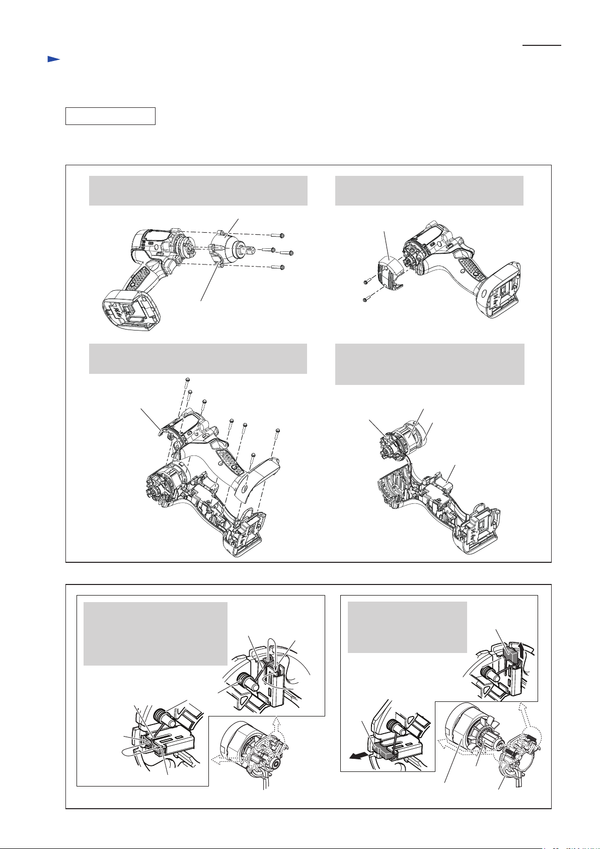
Wiring diagram
Fig. D-3
Wiring of LED Lead Wire (before setting Switch)
Route Lead wires (black, red) between
Rib A and the inner wall of Housing set (L).
Route lead wires (black, red) between Rib A
and Rib B so that they are not pinched
with Switch.
Route Lead wires (black, red) between Rib B
and the inner wall of Housing set (L).
If Connectors are put in Connector box A, route
Lead wires (black, red) through Connector box A
and secure them with Lead wire holder A .
Connectors in Connector Box A
(without Automatic Impact Stop System)
BTW073, BTW103
Rib C
P 12/ 15
LED
Rib A
Rib B
Rib D
Lead wire holder A
Connectors in
Connector box B
Lead wire
holder B
Wiring in Housing set (L) (after setting Switch)
Be careful not to route
any Lead wires on this Rib.
Rib E
Line filter
Place Line filter between Rib E and Rib F.
Note for Wiring:
If Line filter interferes with Housing set (R)
in assembling, check that Insulated terminal
is tilted enough to save the space for Line
filter referring to Fig. D-2.
Connectors can be also routed
through Connector box B.
In this case, Lead wires
have to be secured with Lead
wire holder B.
Rib F
LED
Switch
Route Lead wires connected to Switch
between Boss and the inner wall of
Housing set (L).
Boss
Page 13

Circuit diagram
Fig. D-4
Black
Blue
BTW074, BTW104
(equipped with Automatic Impact Stop System)
Color index of lead wires' sheath
Gray
Green
Orange
Red
P 13/ 15
White
Yellow
Brush holder complete
Brush holder
Line filter*
Switch
Terminal
LED Circuit
(Warning of Power Reduce)
LED Warning
Light
Connector
(4 pin)
Connector
(6 pin)
LED Light
Circuit
Controller
*Line filter is not used for some countries.
Wiring diagram
Fig. D-5
Wiring to M1 Terminal of Switch
1. Secure Insulated terminal to
M1 Terminal with a screw
as shown below.
(equipped with Automatic Impact Stop System)
M1
BTW074, BTW104
2. Bend the Terminal 90º
toward M2 Terminal side
so that Line filter can be
placed on Switch.
M1
M2
Wiring to M2 Terminal of Switch
Secure Insulated terminal to M2 Terminal
tilting approx. 30º±5º as shown below.
30°±5º
M1
M2
Viewed from
Housing set (L) side
Viewed from
Rear side
Viewed from
Housing set (R) side
Page 14

Wiring diagram
Fig. D-6
P 14/ 15
BTW074, BTW104
(equipped with Automatic Impact Stop System)
Wiring of LED Lead Wire (before setting Switch)
Route Lead wires (black, red) between
Rib A and the inner wall of Housing set (L).
Route lead wires (black, red) between
Rib A and Rib B so that they are not pinched
with Switch.
Route Lead wires (black, red) between Rib B
and the inner wall of Housing set (L).
Route Lead wires (black, red) between
the following Ribs.
* Rib of the Boss for Screw hole
* Rib of the Connector box
Wiring of Lead wire of LED Warning Lamp (before setting Switch)
Rib C
Boss
Rib F
LED
Rib A
Rib B
Connector (6 pin) for
connecting to Switch
Connector (4 pin) for
connecting to
LED Warning Light
Rib D
Connector box
LED warning lamp
Route the bundle of Lead wires (blue,
black, red and gray) between Rib A
and the inner wall of Housing set (L).
Route the bundle of Lead wires (blue,
black, red and gray) between Rib B
and the inner wall of Housing set (L).
Route Lead wires (blue, red and gray)
of LED Warning lamp and the
connecting Lead wire (black) between
Rib C and Rib D.
Secure Lead wires of both Connectors
(4 pin) with Lead wire holders.
Rib C
Rib F
LED
Rib A
Rib B
Connector 6 pin for
connecting to Switch
Rib D
Boss
Connector
(4 pin)
Page 15

Wiring diagram
Fig. D-7
Be careful not to route
any Lead wires on this Rib.
P 15/ 15
BTW074, BTW104
(equipped with Automatic Impact Stop System)
Wiring in Housing set (L) (after setting Switch)
Rib E
Route Lead wires of
LED warning lamp
between the Ribs.
LED warning lamp
Be careful not to route
any Lead wires on this Rib.
Secure lead wires of
both Connectors (6 pin)
with Lead wire holders.
Switch
Rib F
LED light
Note for Wiring:
If Line filter interferes with Housing set (R)
in assembling, check that Insulated terminal
is tilted enough to save the space for Line
filter referring to Fig. D-5.
Route Lead wires for connecting
to Switch between Boss and
the inner wall of Housing set (L).
Boss
Line filter
Route Line filter
between Ribs E and F.
 Loading...