

Makita BTD136, BTD147Z, BTD147RFE, BTD147SHE Technical Information
Models No.
Description
PRODUCT
CONCEPT AND MAIN APPLICATIONS
P 1/13
BTD136
Cordless Impact Driver
Specification
Standard equipment
Optional accessories
Note: The standard equipment for the tool shown above may vary by country.
See the model variation list above.
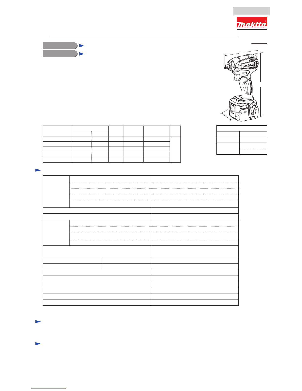
Model BTD136 Cordless Impact Driver is an advanced version of
model BTD133, featuring enhanced dust and drip-proof performance
with a compact body (overall length: 129mm), additionally to
the same
BLDC motor (BrushLess DC motor) and electronic 3-stage
impact power settings with variable power control in each range
as BTD133.
This product is powered by 14.4V- 1.3Ah/ 3.0Ah Li-ion batteries
BL1415/ BL1430.
Battery
No load speed: min.
ˉ¹=rpm
Impacts per min.: min.
ˉ¹=ipm
Max. fastening torque
*5: N.m [kgf.cm] (in.lbs)
Charging time (approx.): min.
Capacities
Electric brake
Reverse switch
Weight according to EPTA-Procedure 01/2003: kg (lbs)
Variable speed control by trigger
Capacity: Ah
Cell
Voltage: V
14.4V
0 - 2,600/ 2,100/ 1,200
0 - 3,200/ 2,600/ 1,100
165 [1,680] (1,460)
Standard bolt
High tensile bolt
Machine screw
Driving shank
M5 - M14 (3/16 - 9/16")
M5 - M12 (3/16 - 1/2")
Coarse-thread
22 - 125mm (7/8 - 4-7/8")
M4 - M8 (5/32 - 5/16")
Yes
Yes
Yes
LED job light Yes
1.2 (2.6)/ 1.4 (3.1)
1.3/ 3.0
Energy capacity: Wh
19/ 44
Li-ion
210
15/ 22 with DC18RC (DC18RA
*4)
6.35mm (1/4") Hex
Max output (W)
*
4 for North and Central American countries
*5 The fastening torque at 3 seconds after seating, when fastening M14 (grade 10.9) high tensile bolt.
This product is available in the following variations.
BTD136SHE
BTD136RFE
BTD136Z
---
BL1430
No
DC18RC
DC18RA
No
Model No.
type quantity
Charger
Yes
Belt
clip
1
No
Battery
cover
Yes
No
Plastic
carrying case
2
BL1430
1 Yes
2
BL1415
DC18SD1 Yes
2
No
No
NoNo No
No
Battery
---
H
W
Dimensions: mm (")
Width (W)
Height (H)
Length (L)
129 (5-1/8)
79 (3-1/8)
221 (8-3/4)*
2
239 (9-3/8)*3
*2: with Battery BL1415
*3: with Battery BL1430
Phillips bits
Socket bits
Drill chucks
Drill bits with 6.35mm Hex shank
Hole saws for Impact driver
Bit piece
Stopper for Impact driver
Hook set (Belt clip)
Tool catcher set
Battery protectors
Li-ion Battery BL1430
Li-ion Battery BL1415
Charger DC18SD
Charger DC24SC
Fast charger DC18RA
(for USA, Canada, Guam, Panama, Colombia, Mexico)
Fast charger DC18RC
(for all countries except the countries above)
Automotive charger DC18SE
Automatic refreshing adapter ADP03
T
ECHNICAL INFORMATION
Impact power selection
Electronic 3 stage (Hard/ Medium/ Soft)
+ Teks screw mode
Hard/ Medium/ Soft
Hard/ Medium/ Soft
OFFICIAL USE
for ASC & Sales Shop

P 2/13
Repair
Apply Makita grease FA No.2 and N No.2 to the following portions indicated by the black triangle to protect
parts and product from unusual abrasion.
[1] NECESSARY REPAIRING TOOLS
CAUTION: Repair the machine in accordance with “Instruction manual” or “Safety instructions”.
Code No. Description Use for
1R041 Vise Plate Fixing Socket 32-50 when disassembling Hammer case
1R045 Gear Extractor Disassembling/assembling Hammer section
1R223 Torque Wrench Shaft 20-90 N.m Disassembling Hammer case
1R224 Ratchet Head 12.7 Disassembling Hammer case (Use with 1R223.)
1R232 Pipe 30 Holding Anvil when disassembling Bit holder section
1R288 Screwdriver Magnetizer Magnetizing a screwdriver for easy removal of steel balls
1R291 Retaining Ring S & R Pliers Removing Ring spring 11 of Bit holder section
134847-1 Socket 30-78 Disassembling/assembling Hammer case
134848-9 Socket 32-50 Disassembling/assembling Hammer case
[2] LUBRICATION
Fig. 1
Item
No.
Description
Hammer case complete
Nylon washer 19
Steel ball 3.5
(24 pcs.)
Hammer
Spur gear 22
a little
a little
a little
a little
Thin washer 12
19
2 g
22
27
27a
27a: Tip portion to be inserted into the hole of Anvil
27b
27b: Insertion hole for Armature for smooth engaging with Spur gear 22
25
Grease
Makita
grease
N No.2
Makita
grease
FA No.2
AmountPortion to lubricate
25 Steel ball 5.6
19 Anvil
22 Flat washer 24
Whole portion
Drum portion that contacts Sleeve 14 and Oil seal 14 of
Hammer case complete
Surface that contacts 24 pcs. of Steel ball 3.5
27 Spindle
27 Spindle
P 3/13
Repair
[3] DISASSEMBLY/ASSEMBLY
[3] -1. Hammer Case Section
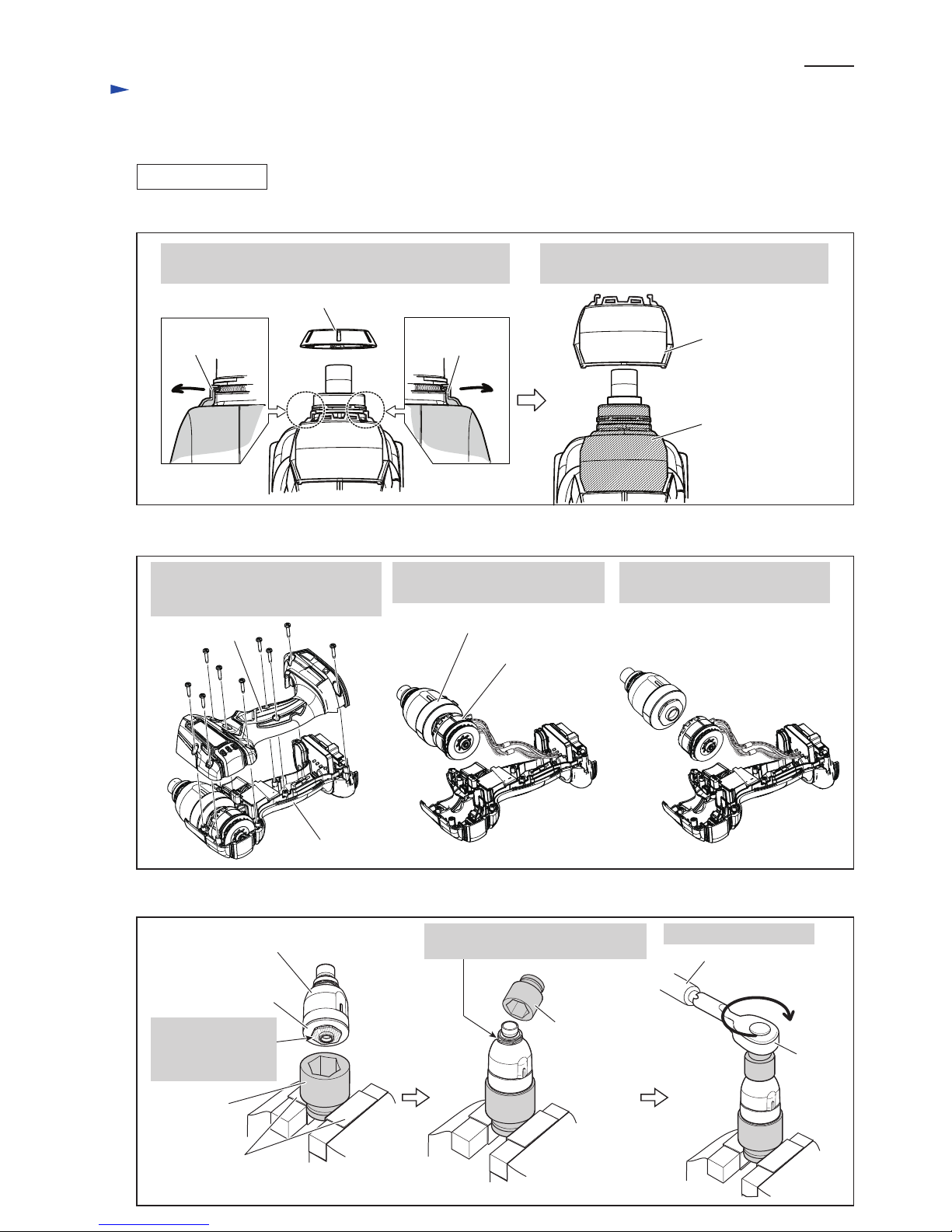
DISASSEMBLING
1. Remove Bumper, then remove the claws of Hammer
case cover from the groove of Hammer case complete.
2. Hammer case cover can now be removed
from Hammer case complete.
claw of Hammer
case cover
claw of Hammer
case cover
Fig. 2
Fig. 3
Bumper
Hammer case cover
(1) Remove Bumper and Hammer case cover. (Fig. 2)
(2) Separate Housing (R) from Housing (L), then remove Hammer case section from Motor section. (Fig. 3)
(3) Remove Hammer case complete from Bearing box complete. (Fig. 4)
Hammer case complete
1. By unscrewing nine 3x16 Tapping
screws, remove Housing (R) from
Housing (L).
2. Remove Hammer case section
together with Motor section.
3. Separate Hammer case section
from Motor section.
Housing (R)
Housing (L)
Motor section
Hammer case section
Fig. 4
Bearing box complete
Socket 32-50
(134848-9)
Socket 30-78
(No.134847-1)
1R041
Vise
Hammer case complete
1R224
Fit this hexagonal
portion in
Hex socket 32-50
(134848-9).
Fit Hex socket 30-78 (No.134847-1)
to this hexagonal portion.
1R223
Turn 1R223 clockwise.
P 4/13
Repair
[3] DISASSEMBLY/ASSEMBLY
[3] -1. Hammer Case Section
DISASSEMBLING
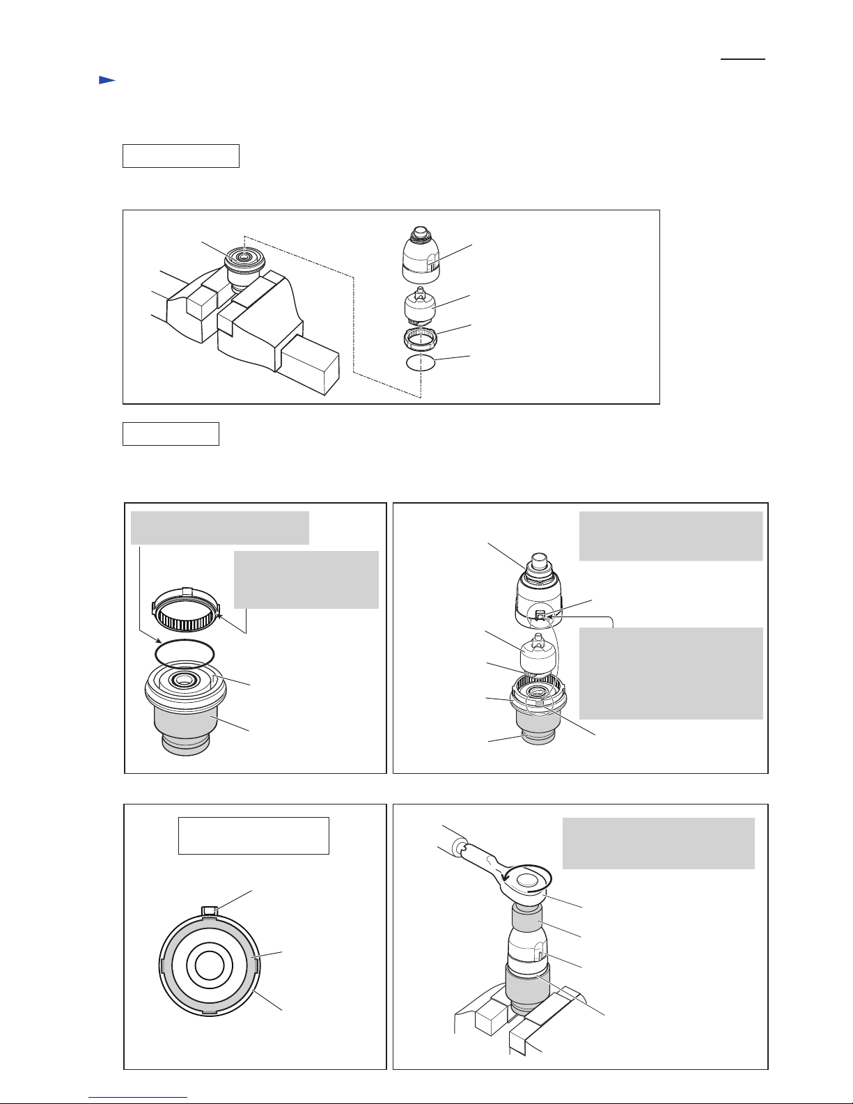
ASSEMBLING
(4) Hammer case section can now be disassembled as shown in Fig. 5.
Fig. 5
Hammer case complete
Hammering mechanism
Internal gear 51
O Ring 40
Bearing box
complete
(1) Assemble Hammer case section. (Figs. 6, 7, 8 and 9)
(2) Mount Hammer case section to Housing in the reverse order of disassembly. (Figs. 3 and 2)
groove of
Bearing box complete
Socket 32-50
(No.134848-9)
Bearing box
complete
Hammer section
Hammer case
complete
Spur gear 22
stopper portion
1. While engaging Spur gear
22 with Internal gear 51,
set Hammer section in place.
Fig. 6
Fig. 8 Fig. 9
Fig. 7
Hammer case complete,
viewed from bottom
Internal gear 51
stopper portion
Hammer case
complete
Socket 32-50
(134848-9)
Turn 1R223 counterclockwise.
Note: The fastening torque must
be 40 to 45 N.m.
protrusion of Internal gear 51
Bearing box complete
1R224
Hammer case complete
Socket 30-78 (134847-1)
1. Put O ring 40 into the groove
of Bearing box complete.
2. Put Internal gear 51 on
Bearing box complete
with its stepped end on
O ring 40.
2. Align the stopper portion of
Hammer case complete with
either one of the 4 protrusions
of Internal Gear 51, then put
Hammer case complete over
Bearing box complete.
 Loading...