

Makita BTD144 User Manual
INSTRUCTION MANUAL
MANUEL D'INSTRUCTION
MANUAL DE INSTRUCCIONES
Cordless Impact Driver
Tournevis à chocs sans fil
Atornillador de impacto inalámbrico
BTD144
009686
WARNING:
For your personal safety, READ and UNDERSTAND before using.
SAVE THESE INSTRUCTIONS FOR FUTURE REFERENCE.
AVERTISSEMENT:
Pour votre propre sécurité, prière de lire attentivement avant l'utilisation.
GARDER CES INSTRUCTIONS POUR RÉFÉRENCE ULTÉRIEURE.
ADVERTENCIA:
Para su seguridad personal, LEA DETENIDAMENTE este manual antes de usar la
herramienta.
GUARDE ESTAS INSTRUCCIONES PARA FUTURA REFERENCIA.
1

ENGLISH
SPECIFICATIONS
Model BTD144
Capacities
No load speed (RPM)
Impacts per minute
Overall length 139 mm (5-1/2")
Net weight (with battery cartridge) 1.3 kg ( 2.8 lbs)
Rated voltage D.C.18 V
• Due to our continuing programme of research and development, the specifications herein are subject to change without notice.
• Note: Specifications may differ from country to country.
Standard battery cartridge BL1815/BL1830
GENERAL SAFETY RULES
WARNING! Read all instructions. Failure to follow all
instructions listed below may result in electric shock, fire
and/or serious injury. The term "power tool" in all of the
warnings listed below refers to your mains-operated
(corded) power tool or battery-operated (cordless) power
tool.
SAVE THESE INSTRUCTIONS.
Work area safety
1. Keep work area clean and well lit. Cluttered and
dark areas invite accidents.
2. Do not operate power tools in explosive
atmospheres, such as in the presence of
flammable liquids, gases or dust. Power tools
create sparks which may ignite the dust or fumes.
3. Keep children and bystanders away while
operating a power tool. Distractions can cause
you to lose control.
Electrical Safety
4. Power tool plugs must match the outlet. Never
modify the plug in any way. Do not use any
adapter plugs with earthed (grounded) power
tools. Unmodified plugs and matching outlets will
reduce risk of electric shock.
5. Avoid body contact with earthed or grounded
surfaces such as pipes, radiators, ranges and
refrigerators. There is an increased risk of
electric shock if your body is earthed or grounded.
6. Do not expose power tools to rain or wet
conditions. Water entering a power tool will
Machine screw 4 mm - 8 mm (5/32" - 5/16")
Standard bolt 5 mm - 14 mm (3/16" - 9/16")
High tensile bolt 5 mm - 12 mm (3/16" - 1/2")
Hammer mode (Hard) 0 - 2,600/min.
Hammer mode (Medium) 0 - 2,000/min.
Hammer mode (Soft) 0 - 1,300/min.
Hammer mode (Hard) 0 - 3,400
Hammer mode (Medium) 0 - 2,800
Hammer mode (Soft) 0 - 1,300
GEA002-3
increase the risk of electric shock.
7. Do not abuse the cord. Never use the cord for
carrying, pulling or unplugging the power tool.
Keep cord away from heat, oil, sharp edges or
moving parts. Damaged or entangled cords
increase the risk of electric shock.
8. When operating a power tool outdoors, use an
extension cord suitable for outdoor use. Use of
a cord suitable for outdoor use reduces the risk of
electric shock.
Personal Safety
9. Stay alert, watch what you are doing and use
common sense when operating a power tool.
Do not use a power tool while you are tired or
under the influence of drugs, alcohol or
medication. A moment of inattention while
operating power tools may result in serious
personal injury.
10. Use safety equipment. Always wear eye
protection. Safety equipment such as dust mask,
non-skid safety shoes, hard hat, or hearing
protection used for appropriate conditions will
reduce personal injuries.
11. Avoid accidental starting. Ensure the switch is
in the off-position before plugging in. Carrying
power tools with your finger on the switch or
plugging in power tools that have the switch on
invites accidents.
12. Remove any adjusting key or wrench before
turning the power tool on. A wrench or a key left
attached to a rotating part of the power tool may
result in personal injury.
13. Do not overreach. Keep proper footing and
balance at all times. This enables better control
2

of the power tool in unexpected situations.
14. Dress properly. Do not wear loose clothing or
jewellery. Keep your hair, clothing, and gloves
away from moving parts. Loose clothes,
jewellery or long hair can be caught in moving
parts.
15. If devices are provided for the connection of
dust extraction and collection facilities,
ensure these are connected and properly used.
Use of these devices can reduce dust-related
hazards.
Power tool use and care
16. Do not force the power tool. Use the correct
power tool for your application. The correct
power tool will do the job better and safer at the
rate for which it was designed.
17. Do not use the power tool if the switch does
not turn it on and off. Any power tool that cannot
be controlled with the switch is dangerous and
must be repaired.
18. Disconnect the plug from the power source
and/or the battery pack from the power tool
before making any adjustments, changing
accessories, or storing power tools. Such
preventive safety measures reduce the risk of
starting the power tool accidentally.
19. Store idle power tools out of the reach of
children and do not allow persons unfamiliar
with the power tool or these instructions to
operate the power tool. Power tools are
dangerous in the hands of untrained users.
20. Maintain power tools. Check for misalignment
or binding of moving parts, breakage of parts
and any other condition that may affect the
power tools operation. If damaged, have the
power tool repaired before use. Many accidents
are caused by poorly maintained power tools.
21. Keep cutting tools sharp and clean. Properly
maintained cutting tools with sharp cutting edges
are less likely to bind and are easier to control.
22. Use the power tool, accessories and tool bits
etc. in accordance with these instructions and
in the manner intended for the particular type
of power tool, taking into account the working
conditions and the work to be performed. Use
of the power tool for operations different from
those intended could result in a hazardous
situation.
Battery tool use and care
23. Ensure the switch is in the off position before
inserting battery pack. Inserting the battery pack
into power tools that have the switch on invites
accidents.
24. Recharge only with the charger specified by
the manufacturer. A charger that is suitable for
one type of battery pack may create a risk of fire
when used with another battery pack.
25. Use power tools only with specifically
designated battery packs. Use of any other
battery packs may create a risk of injury and fire.
26. When battery pack is not in use, keep it away
from other metal objects like paper clips, coins,
keys, nails, screws, or other small metal
objects that can make a connection from one
terminal to another. Shorting the battery
terminals together may cause burns or a fire.
27. Under abusive conditions, liquid may be
ejected from the battery, avoid contact. If
contact accidentally occurs, flush with water. If
liquid contacts eyes, additionally seek medical
help. Liquid ejected from the battery may cause
irritation or burns.
SERVICE
28. Have your power tool serviced by a qualified
repair person using only identical replacement
parts. This will ensure that the safety of the power
tool is maintained.
29. Follow instruction for lubricating and
changing accessories.
30. Keep handles dry, clean and free from oil and
grease.
GEB012-3
SPECIFIC SAFETY RULES
DO NOT let comfort or familiarity with product
(gained from repeated use) replace strict adherence
to impact driver safety rules. If you use this tool
unsafely or incorrectly, you can suffer serious
personal injury.
1.
Hold power tool by insulated gripping surfaces,
when performing an operation where the
fastener may contact hidden wiring or its own
cord.
Fasteners contacting a "live" wire may make
exposed metal parts of the power tool "live" and
could give the operator an electric shock.
2. Always be sure you have a firm footing.
Be sure no one is below when using the tool in
high locations.
3. Hold the tool firmly.
4. Wear ear protectors.
SAVE THESE INSTRUCTIONS.
WARNING:
MISUSE or failure to follow the safety rules stated in
this instruction manual may cause serious personal
injury.
3
USD302-1
Symbols
The followings show the symbols used for tool.
・ volts
・ direct current
・ no load speed
・ revolutions or reciprocation per minute
・ number of blow
ENC007-2
IMPORTANT SAFETY
INSTRUCTIONS
FOR BATTERY CARTRIDGE
1. Before using battery cartridge, read all
instructions and cautionary markings on (1)
battery charger, (2) battery, and (3) product
using battery.
2. Do not disassemble battery cartridge.
3. If operating time has become excessively
shorter, stop operating immediately. It may
result in a risk of overheating, possible burns
and even an explosion.
4. If electrolyte gets into your eyes, rinse them
out with clear water and seek medical
attention right away. It may result in loss of
your eyesight.
5. Do not short the battery cartridge:
(1) Do not touch the terminals with any
conductive material.
(2) Avoid storing battery cartridge in a
container with other metal objects such as
nails, coins, etc.
(3) Do not expose battery cartridge to water
or rain.
A battery short can cause a large current
flow, overheating, possible burns and
6. Do not store the tool and battery cartridge in
7. Do not incinerate the battery cartridge even if
8. Be careful not to drop or strike battery.
even a breakdown.
locations where the temperature may reach or
exceed 50 ゚ C (122 ゚ F).
it is severely damaged or is completely worn
out. The battery cartridge can explode in a fire.
SAVE THESE INSTRUCTIONS.
Tips for maintaining maximum battery life
1. Charge the battery cartridge before completely
discharged.
Always stop tool operation and charge the
battery cartridge when you notice less tool
power.
2. Never recharge a fully charged battery
cartridge.
Overcharging shortens the battery service life.
3. Charge the battery cartridge with room
temperature at 10 ゚ C - 40 ゚ C (50 ゚ F - 104 ゚ F).
Let a hot battery cartridge cool down before
charging it.
FUNCTIONAL DESCRIPTION
CAUTION:
• Always be sure that the tool is switched off and the
battery cartridge is removed before adjusting or
checking function on the tool.
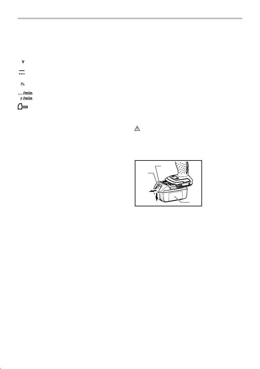
Installing or removing battery cartridge
1
2
009687
• Always switch off the tool before insertion or
removal of the battery cartridge.
• To remove the battery cartridge, withdraw it from
the tool while sliding the button on the front of the
cartridge.
• To insert the battery cartridge, align the tongue on
the battery cartridge with the groove in the housing
and slip it into place. Always insert it all the way
until it locks in place with a little click. If you can
see the red part on the upper side of the button, it
is not locked completely. Insert it fully until the red
part cannot be seen. If not, it may accidentally fall
out of the tool, causing injury to you or someone
around you.
• Do not use force when inserting the battery
cartridge. If the cartridge does not slide in easily, it
is not being inserted correctly.
1. Red part
2. Button
3. Battery
cartridge
3
4
Switch action
1. Switch trigger
1
009208
CAUTION:
• Before inserting the battery cartridge into the tool,
always check to see that the switch trigger
actuates properly and returns to the "OFF" position
when released.
To start the tool, simply pull the switch trigger. Tool
speed is increased by increasing pressure on the switch
trigger. Release the switch trigger to stop.
Electric brake
This tool is equipped with an electric brake. If the tool
consistently fails to quickly stop after switch trigger
release, have tool serviced at a Makita service center.
Lighting up the front lamp
CAUTION:
• Do not look in the light or see the source of light
directly.
1. Lamp
1
009209
009688
Every time the light button
pressed, the light status is alternatively changed from
the ON to the OFF and from the OFF to the ON.
1. Light button
1
on the switch panel is
With the light button in the ON status, pull the switch
trigger to turn on the light. To turn off, release it and the
light goes out approximately 10 seconds after releasing.
With the light button in the OFF status, even if the trigger
is pulled, the lamp will not light on.
NOTE:
• To make sure the status of light, pull the trigger.
When the lamp lights up by pulling the switch
trigger, the light switch is in the ON status. When
the lamp does not come on, the light switch is in
the OFF status.
• During the operation of switch trigger, the light
status cannot be changed.
• For approximately 10 seconds after releasing the
switch trigger, the light status can be switched.
Reversing switch action
1. Reversing
switch lever
A
B
1
009211
This tool has a reversing switch to change the direction
of rotation. Depress the reversing switch lever from the A
side for clockwise rotation or from the B side for
counterclockwise rotation.
When the reversing switch lever is in the neutral position,
the switch trigger cannot be pulled.
CAUTION:
• Always check the direction of rotation before
operation.
• Use the reversing switch only after the tool comes
to a complete stop. Changing the direction of
rotation before the tool stops may damage the tool.
• When not operating the tool, always set the
reversing switch lever to the neutral position.
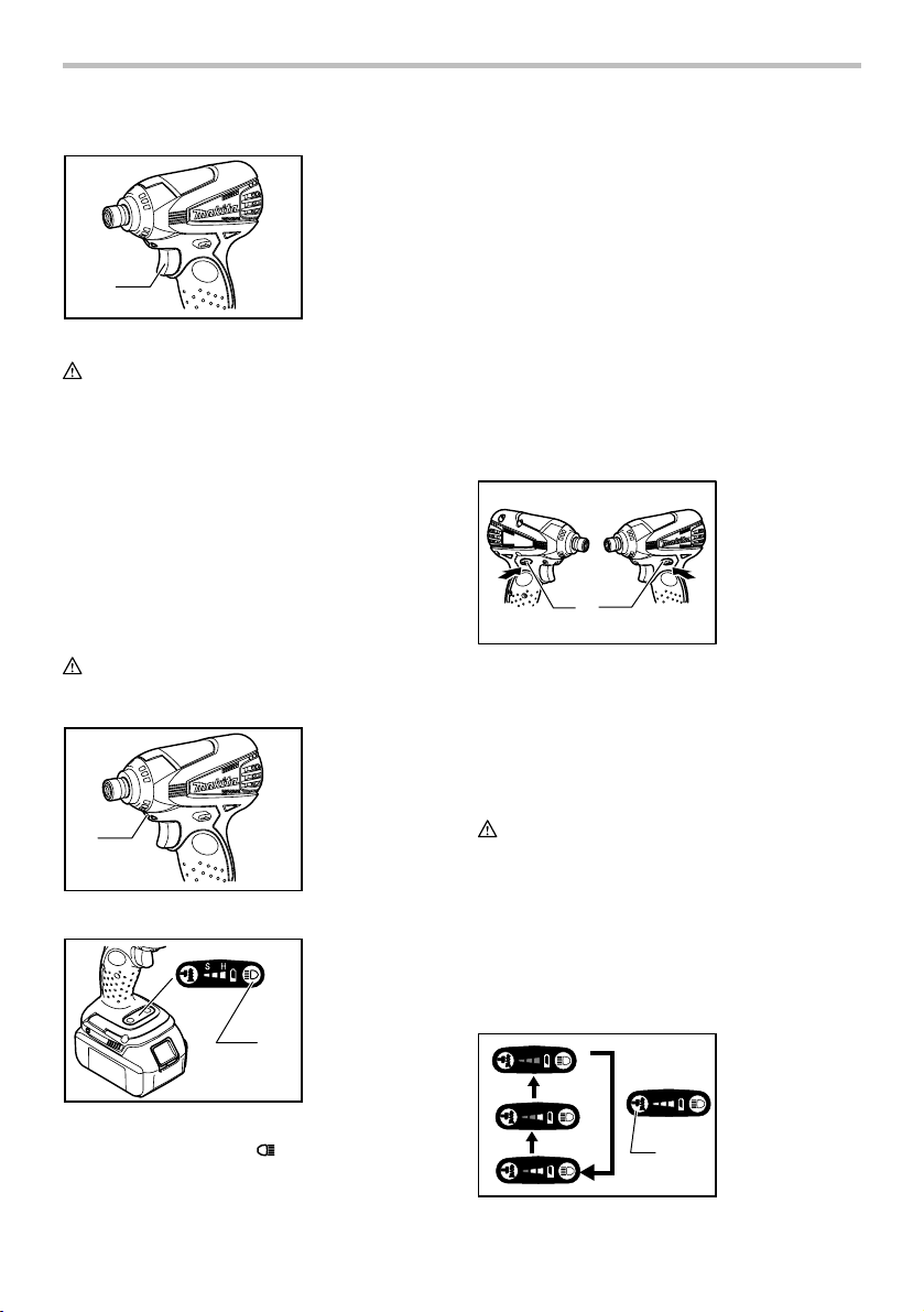
Changing the hammering force
5
2
3
4
009212
SH
SH
SH
1
S
5
1. Changed in
three steps
2. Hard
H
3. Medium
4. Soft
5. Hammering
force button
Hammering force grade
displayed on panel
Maximum blows Application Work
Hard
SH
Medium
SH
Soft
SH
009801
The hammering force can be changed in three steps:
hard, medium and soft.
This allows a tightening suitable to the work.
Every time the hammering force button
number of blows changes in three steps.
For approximately one minute after releasing the switch
trigger, the hammering force can be changed.
NOTE:
• When all lamps on the switch panel go out, the tool
is turned off to save the battery power. The
hammer force grade can be checked by pulling the
switch trigger to the extent that the tool does not
operate.
• During the operation of switch trigger, the hammer
force grade cannot be changed.
3,400 /min.
2,800 /min.
1,300 /min.
Tightening when force
and speed are desired.
Tightening when a good
finishing is needed.
Tightening when excessive
tightening need to be avoided
because of potentially clogged
female screw and broken or
damaged screw head.
is pressed, the
Tightening in underwork
material/ Tightening long
screws/ Tightening bolts.
Tightening in the finishing
board, plaster board.
Tightening sash screw/
Tightening small screws
such as M6.
Empty signal for remaining
battery capacity
1. LED indicator
1
009691
Pulling the trigger switch when the remaining battery
capacity become very low makes LED indicator lights
up.
If the tool is used continuously with the LED indicator
lighting up and the battery power is almost used up, the
LED indicator will flicker and the tool itself will stop
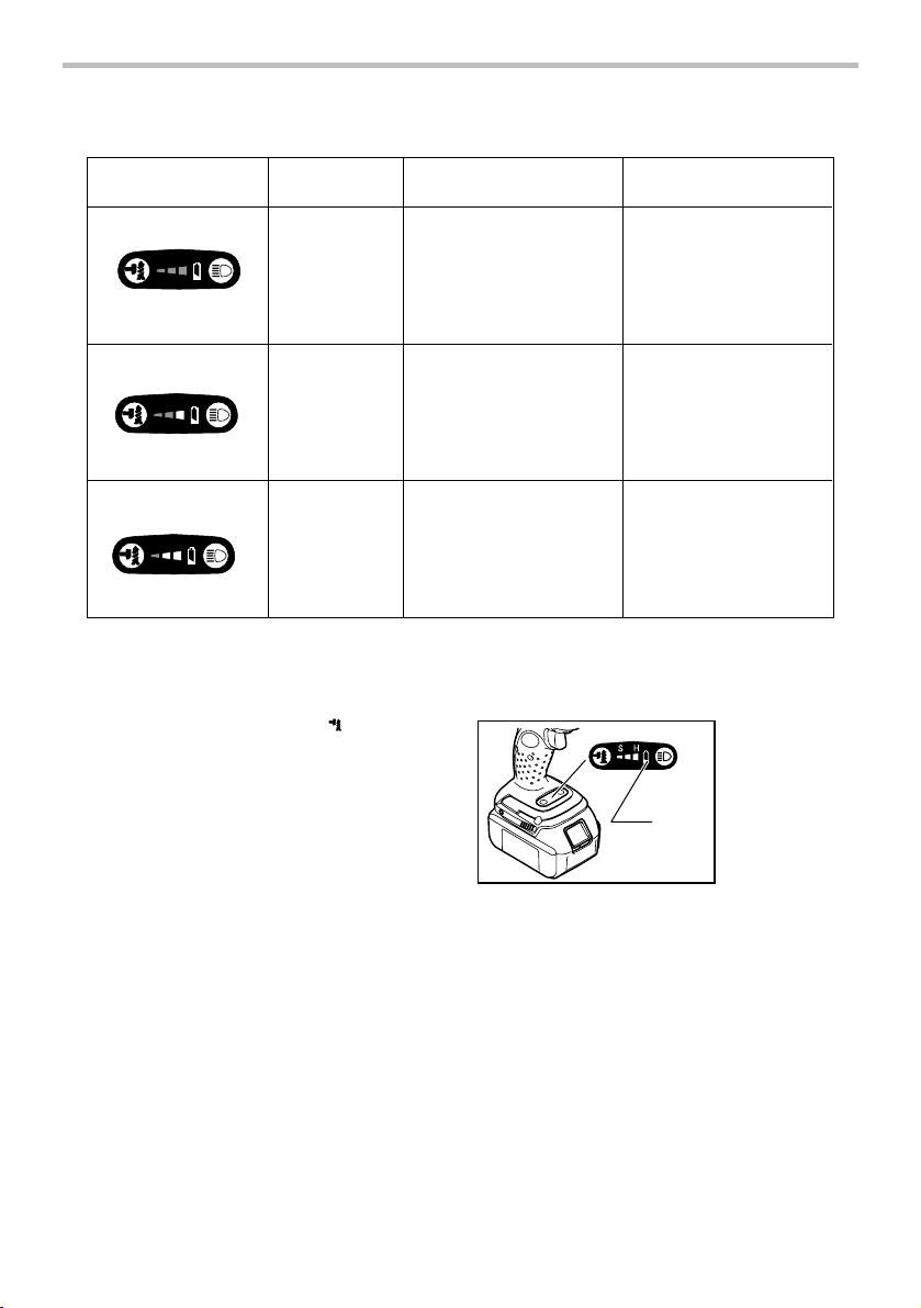
Please refer to the following table for the LED indicator
status and the remaining battery capacity.
6
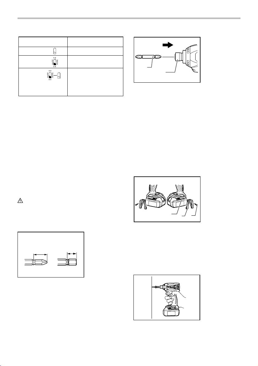
LED indicator status
OFF
Remaining battery capacity
Enough
1. Bit
2. Sleeve
Lighting on
Flickering
The light also flickers three
times a second at the same
time.
009214
Very low and the tool will stops
20%
NOTE:
• When all lamps on the switch panel go out, the tool
is turned off to save the battery power. The
remaining battery capacity can be checked by
pulling the switch trigger to the extent that the tool
does not operate.
• All of the lamps on the switch panel go out
approximately one minute after releasing the
switch trigger.
• If the LED indicator flickers and the tool stops even
with a recharged battery cartridge, stop using and
have the tool repaired by a Makita local service
center.
ASSEMBLY
CAUTION:
• Always be sure that the tool is switched off and the
battery cartridge is removed before carrying out
any work on the tool.
Installing or removing driver bit or socket bit
12 mm
(15/32”)
001266
Use only the driver bit or socket bit shown in the figure.
Do not use any other driver bit or socket bit.
To install the bit, insert the bit into the sleeve as far as it
will go.
9 mm
(3/8”)
1
2
009205
To remove the bit, pull the sleeve in the direction of the
arrow and pull the bit out firmly.
NOTE:
• If the bit is not inserted deep enough into the
sleeve, the sleeve will not return to its original
position and the bit will not be secured. In this case,
try re-inserting the bit according to the instructions
above.
• When it is difficult to insert the bit, pull the sleeve
and insert it into the sleeve as for as it will go.
• After inserting the bit, make sure that it is firmly
secured. If it comes out, do not use it.
Hook
1. Groove
2. Hook
3. Screw
1
2
3
009689
The hook is convenient for temporarily hanging the tool.
This can be installed on either side of the tool.
To install the hook, insert it into a groove in the tool
housing on either side and then secure it with a screw.
To remove, loosen the screw and then take it out.
OPERATION
009690
The proper fastening torque may differ depending upon
7
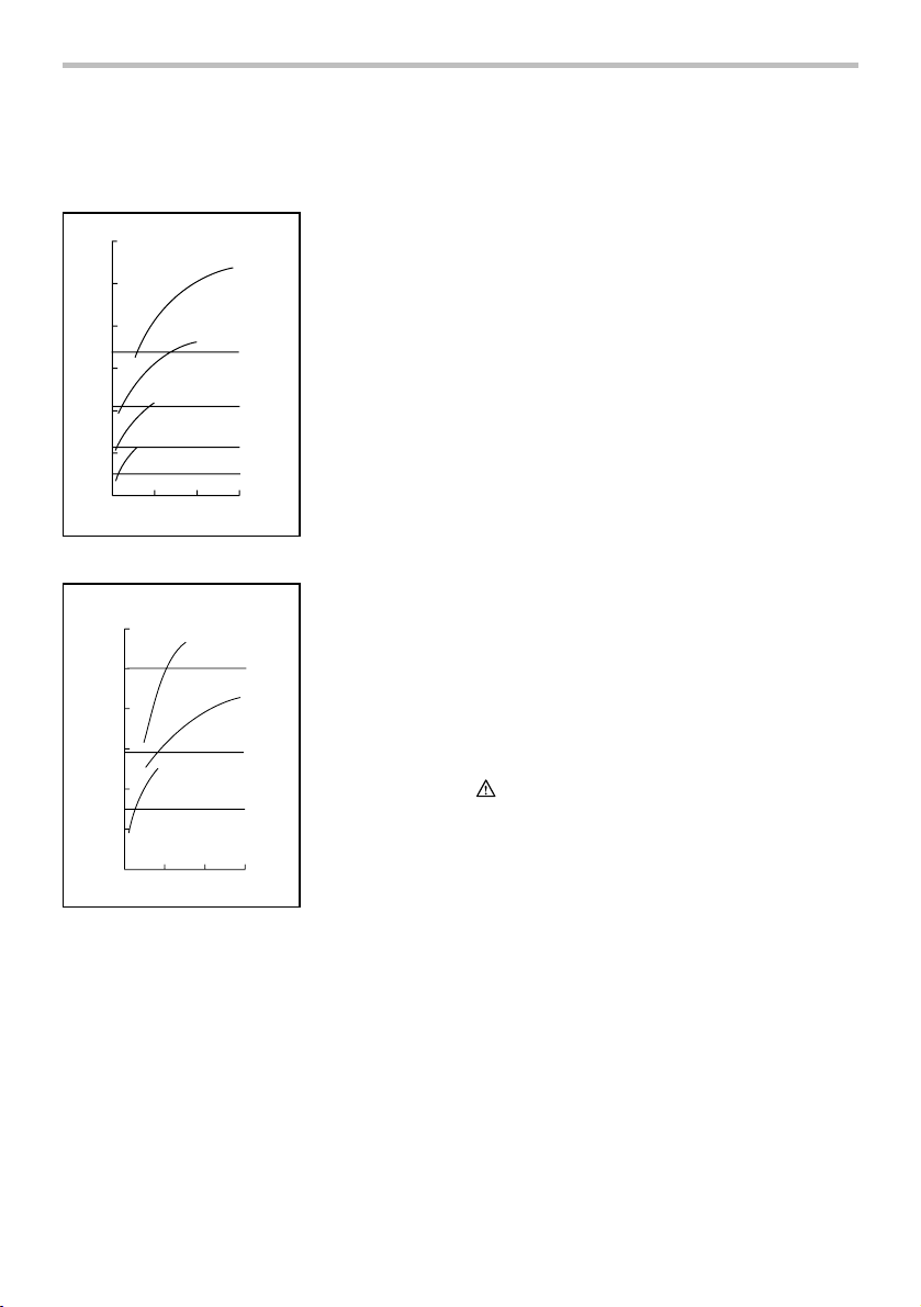
the kind or size of the screw/bolt, the material of the
workpiece to be fastened, etc. The relation between
fastening torque and fastening time is shown in the
figures.
N.m
Standard bolt
(ft.lbs)
120
(87)
100
(72)
80
(58)
60
(43)
40
(29)
Fastening torque
20
(14)
0 1.0 2.0 3.0
Fastening time
009220
M8
M10
(5/16")
(3/8")
M12
M14
(9/16")
(1/2")
(M14)
(9/16")
(M12)
(1/2")
(M10)
(3/8")
(M8)
(5/16")
(S)
Proper fastening torque
N.m
(ft.lbs)
120
(87)
100
(72)
(58)
Fastening torque
009221
High tensile bolt
80
60
(43)
(29)
(14)
40
20
(5/16")
M8
0 1.0 2.0 3.0
Fastening time
M12
(3/8")
M10
(1/2")
(M12)
(1/2")
(M10)
(3/8")
(M8)
Proper fastening torque
(5/16")
(S)
Hold the tool firmly and place the point of the driver bit in
the screw head. Apply forward pressure to the tool to the
extent that the bit will not slip off the screw and turn the
tool on to start operation.
NOTE:
• Use the proper bit for the head of the screw/bolt
that you wish to use.
• When fastening screw M8 or smaller, choose a
proper hammer force carefully adjust pressure on
the switch trigger so that the screw is not
damaged.
• Hold the tool pointed straight at the screw.
• If the hammering force is too strong you tighten the
screw for a time longer than shown in the figures,
the screw or the point of the driver bit may be
overstressed, stripped, damaged, etc. Before
starting your job, always perform a test operation
to determine the proper fastening time for your
screw.
The fastening torque is affected by a wide variety of
factors including the following. After fastening, always
check the torque with a torque wrench.
1. When the battery cartridge is discharged almost
completely, voltage will drop and the fastening
torque will be reduced.
2. Driver bit or socket bit
Failure to use the correct size driver bit or socket
bit will cause a reduction in the fastening torque.
3. Bolt
• Even though the torque coefficient and the
class of bolt are the same, the proper
fastening torque will differ according to the
diameter of bolt.
• Even though the diameters of bolts are the
same, the proper fastening torque will differ
according to the torque coefficient, the class of
bolt and the bolt length.
4. The manner of holding the tool or the material of
driving position to be fastened will affect the
torque.
5. Operating the tool at low speed will cause a
reduction in the fastening torque.
MAINTENANCE
CAUTION:
• Always be sure that the tool is switched off and the
battery cartridge is removed before attempting to
perform inspection or maintenance except for the
following troubleshooting related to the light.
8

Troubleshooting
Trouble
Light status Steps to be taken
Flickers twice per
second.
The tool temperature is high.Cool down it fully.
The tool restarts after its temperature becomes low.
Flickers three times per
second.
(LED indicator for
empty signal for
remaining battery
The tool stops
capacity also flickers.)
during operation.
Flickers five times per
second.
Flickers once
per second.
Not flickers
009217
To maintain product SAFETY and RELIABILITY, repairs,
any other maintenance or adjustment should be
performed by Makita Authorized or Factory Service
Centers, always using Makita replacement parts.
ACCESSORIES
CAUTION:
• These accessories or attachments are
recommended for use with your Makita tool
specified in this manual. The use of any other
accessories or attachments might present a risk of
injury to persons. Only use accessory or
attachment for its stated purpose.
If you need any assistance for more details regarding
these accessories, ask your local Makita Service Center.
• Screw bits
• Hook
• Plastic carrying case
• Various type of Makita genuine batteries and
chargers
Remaining battery capacity level is low. Charge the
battery cartridge.When the LED indicator still flickers
even after charging the battery cartridge, stop using
and have the tool repaired by a Makita local service
center.
Use the tool with the motor not locked.If the motor
remains locked, stop using and have the tool
repaired by
a Makita local service center.
Stop using and have the tool repaired by a Makita
local service center.
The tool stops when continuing to pull the switch
trigger for more than approximately 2 mi
nutes.
Release the switch trigger.
9

MAKITA LIMITED ONE YEAR WARRANTY
Warranty Policy
Every Makita tool is thoroughly inspected and tested
before leaving the factory. It is warranted to be free of
defects from workmanship and materials for the period
of ONE YEAR from the date of original purchase.
Should any trouble develop during this one year period,
return the COMPLETE tool, freight prepaid, to one of
Makita’s Factory or Authorized Service Centers. If
inspection shows the trouble is caused by defective
workmanship or material, Makita will repair (or at our
option, replace) without charge.
This Warranty does not apply where:
repairs have been made or attempted by others:
repairs are required because of normal wear and
tear:
the tool has been abused, misused or improperly
maintained:
alterations have been made to the tool.
IN NO EVENT SHALL MAKITA BE LIABLE FOR ANY
INDIRECT, INCIDENTAL OR CONSEQUENTIAL
DAMAGES FROM THE SALE OR USE OF THE
PRODUCT. THIS DISCLAIMER APPLIES BOTH
DURING AND AFTER THE TERM OF THIS
WARRANTY.
MAKITA DISCLAIMS LIABILITY FOR ANY IMPLIED
WARRANTIES, INCLUDING IMPLIED WARRANTIES
OF "MERCHANTABILITY" AND "FITNESS FOR A
SPECIFIC PURPOSE," AFTER THE ONE YEAR TERM
OF THIS WARRANTY.
This Warranty gives you specific legal rights, and you
may also have other rights which vary from state to
state. Some states do not allow the exclusion or
limitation of incidental or consequential damages, so
the above limitation or exclusion may not apply to you.
Some states do not allow limitation on how long an
implied warranty lasts, so the above limitation may not
apply to you.
EN0006-1
10
 Loading...