

Makita BTD140, BTD140SFE Technical Information

T
ECHNICAL INFORMATION
Models No.
BTD140
PRODUCT
P 1 / 9
Description
Cordless Impact Driver
CONCEPT AND MAIN APPLICATIONS
Model BTD140 has been developed as the 18V version of the current 14.4V Cordless
impact driver Model BTD130F.
18V battery delivers powerful 220W maximum output, yet still extra-lightweight design
has been achieved by using 4-pole motor and Lithium-ion battery as power unit.
Features the same advantages as BTD130F as follows:
High operation efficiency
Hammer case without protrusion
Job light with afterglow function
Belt clip
This new product will be available in the following variations.
Model No.
BTD140
(Li-ion 3.0Ah)
BTD140SFE
Specification
Battery
type quantity
BL1830
Charger Offered to
USA, Canada
2
DC18SC
Mexico, Panama
All countries except
those listed above
Dimensions: mm (")
Length (L)
Width (W)
Height (H)
146 (5-3/4)
79 (3-1/8)
235 (9-1/4)
Voltage: V
Battery
Max output (W)
Driving shank
Capacities
Impacts per min.: min.-1=bpm
No load speed: min.-1=rpm
Max. fastening torque: N.m (in.lbs)
Electric Brake
Variable speed (electric)
Reversing switch
Net weight*: kg (lbs)
*Includes battery BL1830
Capacity: Ah
Cell
Machine screw
Standard bolt
High tensile bolt
Coarse thread screw
6.35mm (1/4") Hex
M4 - M8 (5/32 - 5/16")
M5 - M14 (3/16 - 9/16")
M5 - M12 (3/16 - 15/32")
22 - 125mm (7/8 - 4-7/8")
18
3.0
Li-ion
220
0 - 3,200
0 - 2,300
145 (1,280)
Yes
Yes
Yes
1.5 (3.3)
Standard equipment
Belt clip ................................... 1
Plastic carrying case ................ 1
Note: The standard equipment for the tool shown above may differ by country.
Optional accessories
Charger DC18SC
Charger DC24SA
Charger DC24SC
Li-ion Battery 1830
Assorted Phillips bits
Assorted socket bits
Bit piece
Repair
CAUTION: Remove the battery from the machine for safety before repair/ maintenance !
[1] NECESSARY REPAIRING TOOLS
P 2 / 9
Code No.
1R045
1R346 Center attachment for 1R045
1R288 Screwdriver magnetizer
1R232 Pipe 30
1R291 Retaining ring S and R pliers
1R041 Vise plate
1R223 Torque wrench shaft
1R224 Ratchet head
134847-1 Socket 30-78
134848-9
Gear extractor (Large)
Socket 32-50
Description
Use for
Disassembling Hammer mechanism
Magnetizing screwdriver for removing Steel balls
Disassembling Bit holder mechanism
Fixing Hammer case
Turning Hammer case
Fixing Hammer case
when disassembling Hammer mechanism
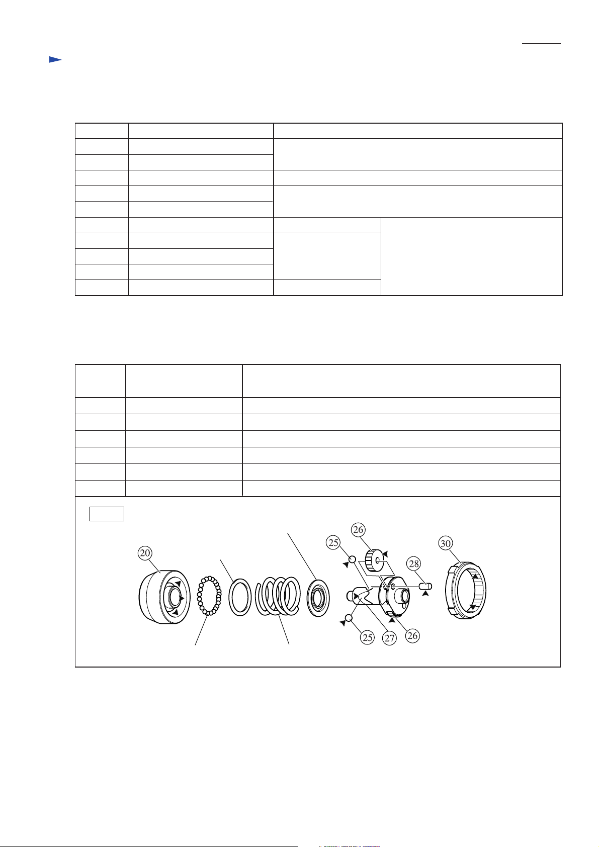
[2] LUBRICATION
Apply Makita grease N. No.2 to the following portions designated with the black triangle to protect
parts and product from unusual abrasion.
Item No.
20
25
26
27 Spindle Cam groove top
28
30
Part description
Hammer case complete Inside surface where twenty-four 3.5 Steel balls are installed
Steel ball 5.6
Spur gear 22
Pin 5
Internal gear 51
Whole surface
Gear teeth
Surface that contacts Spur gear 22
Gear teeth that engages with Spur gear 22 (Apply approx. 2g.)
Where to lubricate
Fig. 1
Cup washer 14
Flat washer 24
Steel ball 3.5 (24 pcs) Compression spring 24
Repair
[3] DISASSEMBLY/ASSEMBLY
[3] -1. Disassembling/Assembling Hammering Mechanism
P 3 / 9
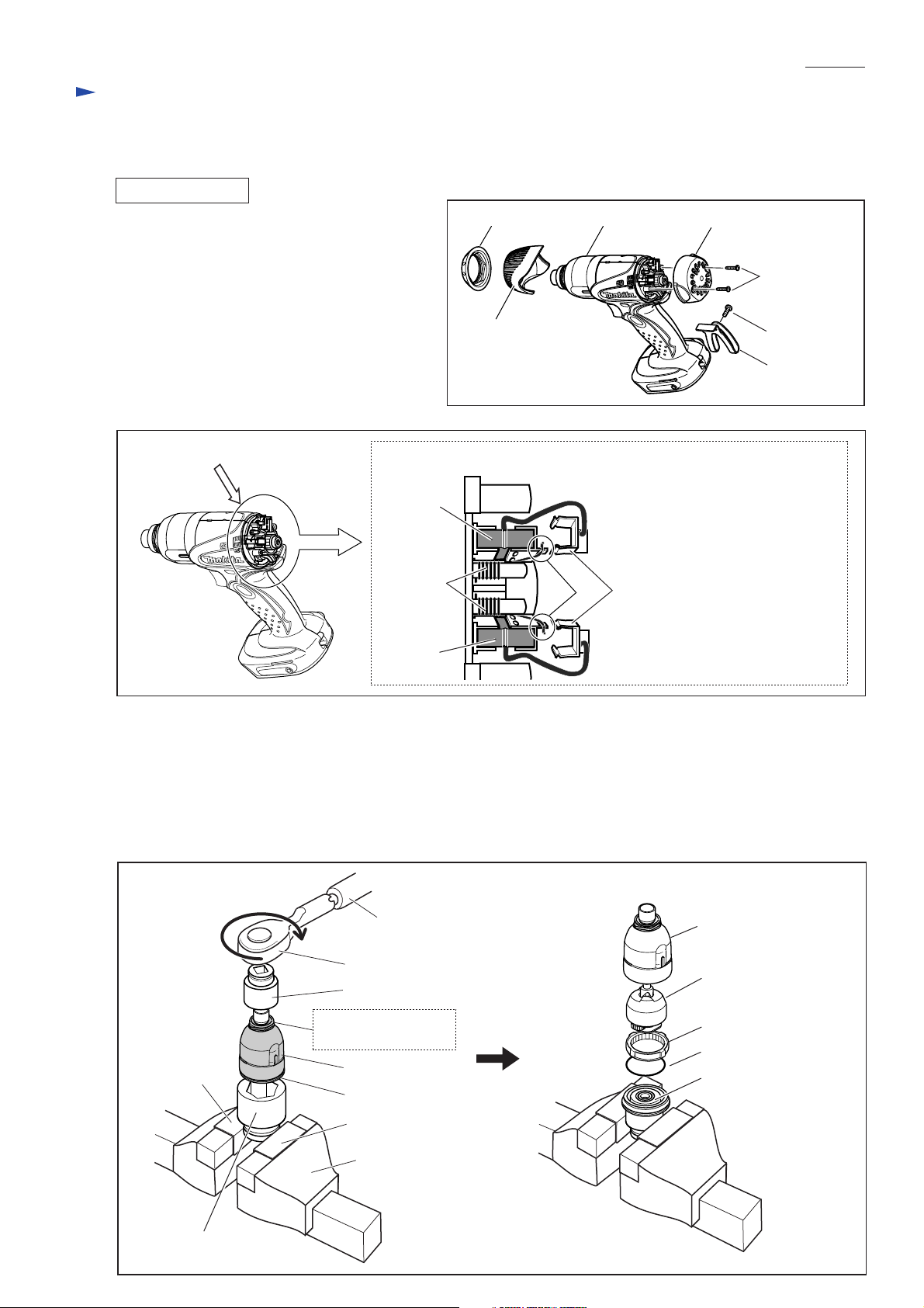
DISASSEMBLING
1) Remove Belt clip by unscrewing Screw M4x12.
After removing Bumper and Hammer case cover
by hand, then remove Rear cover by unscrewing
two PT3x16 Tapping screws. (Fig. 2)
2) Shift the tail of torsion spring from Carbon brush
onto the notch in Brush holder.
Then pull off Receptacle from Brush holder.
Now Carbon brush can be removed from Brush
holder. (Fig. 3)
Fig. 3
A
[Brush holder section (View from A)]
Carbon
brush
Torsion
spring
Fig. 2
Hammer case cover
Hammer caseBumper
1 2
Rear cover
Tapping screw
PT3x16 (2 pcs)
Screw M4x12
Belt clip
1. Shift the tail of Torsion spring
onto the notch of Brush holder.
2. Then pull off Receptacle from
Brush holder.
Carbon
brush
3) Separate Housing (R) from Housing (L) by removing eight PT3x16 Tapping screws.
4) Remove the assembly of the Hammer case section and the Motor section from Housing (L), then separate the Hammer
case from the Motor section.
5) Attach a pair of Vise plate (No.1R041) to vise. Fix Socket 32-50 in vise securely. Then put the Hammer case section
on Socket 32-50 while fitting the hexagonal portion of Bearing box in Socket 32-50. Fit Socket 30-78 over the hex agonal portion of Hammer case. Then, by turning Socket 30-78 with Torque wrench shaft 20-90N.m (No.1R223) and
Ratchet head with 12.7mm square (No.1R224) clockwise, the Hammer case section can be disassembled. (Fig. 4)
Fig. 4
Hammer case
Hammering mechanism
Internal gear 51
O ring 40
Bearing box
Vise plate
No.1R223
No.1R224
Socket 30-78
Fit socket 30-78 over
this hex portion.
Hammer case
Bearing box
Socket 32-50
Vise plate
Vise
 Loading...