

Page 1
GB
Cordless Impact Driver Instruction Manual
F Visseuse à chocs sans fil
D Akku-Schlagschrauber
I Avvitatore ad impulso a batteria
NL Accu-slagschroevendraaier
E Atornillador de impacto a batería
P Berbequim de impacto a bateria
DK Akku slagskruetrækker
S Sladdlös hammarskruvdragare
N Batteridrevet slagtrekker
SF Iskevä akkuruuvinväännin
GR Ασύρµατ κρουστικ βιδοτρύπανο Οδηγίες χρήσεως
Manuel d’instructions
Betriebsanleitung
Istruzioni per l’uso
Gebruiksaanwijzing
Manual de instrucciones
Manual de instruções
Brugsanvisning
Bruksanvisning
Bruksanvisning
Käyttöohje
BTD123F
Page 2
2
1
4
3
12
A
5
6
B
34
A
B
7
8
9
56
10
7
9
11
78
2
Page 3
12
13
N.m
(kgf.cm)
80
(1020)
60
(612)
40
(408)
20
(204)
M12
M10
14
(M12)
(M10)
M8
(M8)
0
1.0 2.0
s
15
16
13
N.m
(kgf.cm)
80
(1020)
60
(612)
40
(408)
20
(204)
0
1.0
15
(M10)
M8
(M8)
2.0
M10
14
s
910
19
17
10 11
18
3
Page 4

ENGLISH
1Button
2 Red part
3 Battery cartridge
4 Switch trigger
5Lamp
6 Reversing switch lever
7Bit
Explanation of general view
8 Bit-piece
9Sleeve
10 Expand
11 Hook
12 Standard bolt
13 Fastening torque
14 Proper fastening torque
15 Fastening time
16 High tensile bolt
17 Limit mark
18 Brush holder cap
19 Screwdriver
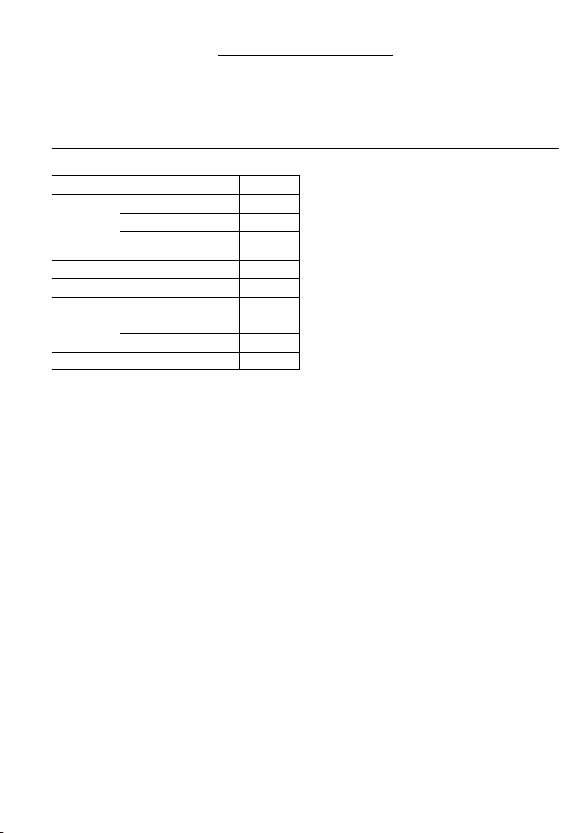
SPECIFICATION
Model BTD123F
Machine screw M4 – M8
Capacities
No load speed (min
Impacts per minute 0 – 3,200
Net weight
• Due to our continuing program of research and development, the specifications herein are subject to change
without notice.
• Note: Specifications may differ from country to country.
Intended use
The tool is intended for screw driving in wood, metal and
plastic.
Safety hints
For your own safety, please refer to the enclosed safety
instructions.
Standard bolt M5 – M12
High tensile bolt M5 – M10
–1
)0–2,600
Overall length 163 mm
With 2.0 Ah battery 1.4 kg
With 3.3 Ah battery 1.6 kg
Rated voltage D.C. 12 V
SPECIFIC SAFETY RULES
DO NOT let comfort or familiarity with product
GEB012-2
(gained from repeated use) replace strict
adherence to impact driver safety rules. If you
use this tool unsafely or incorrectly, you can
suffer serious personal injury.
1. Hold power tools by insulated gripping surfaces
when performing an operation where the cutting
tool may contact hidden wiring or its own cord.
Contact with a “live” wire will make exposed metal
parts of the tool “live” and shock the operator.
2. Always be sure you have a firm footing. Be sure
no one is below when using the tool in high locations.
3. Hold the tool firmly.
4. Wear ear protectors.
SAVE THESE INSTRUCTIONS.
WARNING:
MISUSE or failure to follow the safety rules stated
in this instruction manual may cause serious personal injury.
IMPORTANT SAFETY INSTRUCTIONS FOR
CHARGER & BATTERY CARTRIDGE
1. Before using battery cartridge, read all instructions and cautionary markings on (1) battery
charger, (2) battery, and (3) product using battery.
2. Do not disassemble battery cartridge.
3. If operating time has become excessively
shorter, stop operating immediately. It may result
in a risk of overheating, possible burns and even
an explosion.
4. If electrolyte gets into your eyes, rinse them out
with clear water and seek medical attention right
away. It may result in loss of your eyesight.
5. Do not short the battery cartridge:
(1) Do not touch the terminals with any conduc-
tive material.
(2) Avoid storing battery cartridge in a container
with other metal objects such as nails, coins,
etc.
(3) Do not expose battery cartridge to water or
rain.
A battery short can cause a large current flow,
overheating, possible burns and even a breakdown.
6. Do not store the tool and battery cartridge in
locations where the temperature may reach or
exceed 50°C (122°F).
7. Do not incinerate the battery cartridge even if it
is severely damaged or is completely worn out.
The battery cartridge can explode in a fire.
8. Be careful not to drop or strike battery.
ENC005-1
SAVE THESE INSTRUCTIONS.
Tips for maintaining maximum battery life
1. Charge the battery cartridge before completely
discharged.
Always stop tool operation and charge the battery cartridge when you notice less tool power.
2. Never recharge a fully charged battery cartridge.
Overcharging shortens the battery service life.
3. Charge the battery cartridge with room temperature at 10°C – 40°C (50°F – 104°F). Let a hot battery cartridge cool down before charging it.
4. Charge the Nickel Metal Hydride battery cartridge when you do not use it for more than six
months.
4
Page 5
FUNCTIONAL DESCRIPTION
CAUTION:
• Always be sure that the tool is switched off and the battery cartridge is removed before adjusting or checking
function on the tool.
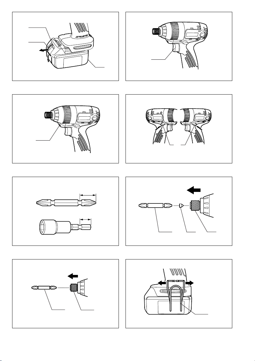
Installing or removing battery cartridge (Fig. 1)
• Always switch off the tool before insertion or removal of
the battery cartridge.
• To remove the battery cartridge, withdraw it from the
tool while sliding the button on the cartridge.
• To insert the battery cartridge, align the tongue on the
battery cartridge with the groove in the housing and slip
it into place. Always insert it all the way until it locks in
place with a little click. If you can see the red part on
the upper side of the button, it is not locked completely.
Insert it fully until the red part cannot be seen. If not, it
may accidentally fall out of the tool, causing injury to
you or someone around you.
• Do not use force when inserting the battery cartridge. If
the cartridge does not slide in easily, it is not being
inserted correctly.
Switch action (Fig. 2)
CAUTION:
• Before inserting the battery cartridge into the tool,
always check to see that the switch trigger actuates
properly and returns to the “OFF” position when
released.
To start the tool, simply pull the switch trigger. Tool speed
is increased by increasing pressure on the switch trigger.
Release the switch trigger to stop.
Lighting up the front lamp (Fig. 3)
CAUTION:
• Do not look in the light or see the source of light
directly.
Pull the switch trigger to light up the lamp. The lamp
keeps on lighting while the switch trigger is being pulled.
NOTE:
• Use a dry cloth to wipe the dirt off the lens of lamp. Be
careful not to scratch the lens of lamp, or it may lower
the illumination.
Reversing switch action (Fig. 4)
This tool has a reversing switch to change the direction of
rotation. Depress the reversing switch lever from the A
side for clockwise rotation or from the B side for counterclockwise rotation.
When the reversing switch lever is in the neutral position,
the switch trigger cannot be pulled.
CAUTION:
• Always check the direction of rotation before operation.
• Use the reversing switch only after the tool comes to a
complete stop. Changing the direction of rotation
before the tool stops may damage the tool.
• When not operating the tool, always set the reversing
switch lever to the neutral position.
ASSEMBLY
CAUTION:
• Always be sure that the tool is switched off and the battery cartridge is removed before carrying out any work on the
tool.
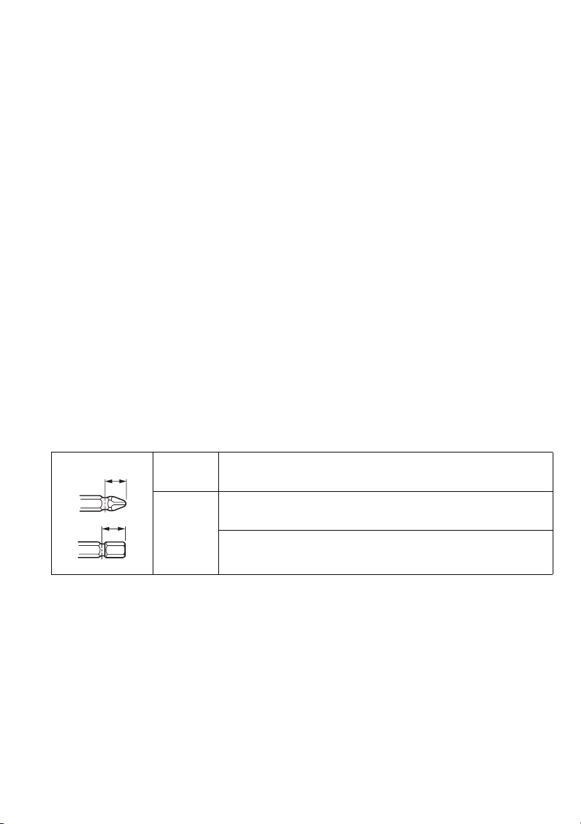
Installing or removing driver bit or socket bit
Use only the driver bit or socket bit shown in the figure. Do not use any other driver bit or socket bit. (Fig. 5)
A
B
1. To install the bit, pull the sleeve in the direction of the arrow and insert the bit into the sleeve as far as it will go.
Then release the sleeve to secure the bit. (Fig. 6)
2. To install the bit, pull the sleeve in the direction of the arrow and insert the bit-piece and bit into the sleeve as far as
it will go. The bit-piece should be inserted into the sleeve with its pointed end facing in. Then release the sleeve to
secure the bit. (Fig. 7)
To remove the bit, pull the sleeve in the direction of the arrow and pull the bit out firmly.
NOTE:
• If the bit is not inserted deep enough into the sleeve, the sleeve will not return to its original position and the bit will
not be secured. In this case, try re-inserting the bit according to the instructions above.
A= 17mm
B= 14mm
A= 12mm
B= 9mm
To install these types of bits, follow the procedure (1).
(Note) Makita bits are these types.
To install these types of bits, follow the procedure (2).
(Note) Bit-piece is necessary for installing the bit.
For European and North & South American countries
Use only these types of bits. Follow the procedure (1).
(Note) Bit-piece is not necessary.
5
Page 6

Hook (Accessory) (Fig. 8)
The hook is convenient for temporarily hanging the tool.
This can be removed without using a tool. This can be
installed on either side of the tool.
To remove the hook, expand the upper part of the hook in
both directions and remove it. To install the hook, follow
the removal procedure in reverse.
OPERATION
CAUTION:
• Always insert the battery cartridge all the way until it
locks in place. If you can see the red part on the upper
side of the button, it is not locked completely. Insert it
fully until the red part cannot be seen. If not, it may
accidentally fall out of the tool, causing injury to you or
someone around you.
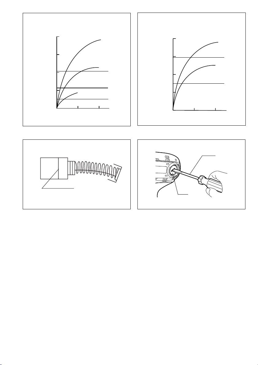
The proper fastening torque may differ depending upon
the kind or size of the screw/bolt, the material of the
workpiece to be fastened, etc. The relation between fastening torque and fastening time is shown in the figures.
(Fig. 9 & 10)
Hold the tool firmly and place the point of the driver bit in
the screw head. Apply forward pressure to the tool to the
extent that the bit will not slip off the screw and turn the
tool on to start operation.
NOTE:
• Use the proper bit for the head of the screw/bolt that
you wish to use.
• When fastening screw M8 or smaller, carefully adjust
pressure on the switch trigger so that the screw is not
damaged.
• Hold the tool pointed straight at the screw.
• If you tighten the screw for a time longer than shown in
the figures, the screw or the point of the driver bit may
be overstressed, stripped, damaged, etc. Before starting your job, always perform a test operation to determine the proper fastening time for your screw.
• If the tool is operated continuously until the battery cartridge has discharged, allow the tool to rest for 15 minutes before proceeding with a fresh battery.
The fastening torque is affected by a wide variety of factors including the following. After fastening, always check
the torque with a torque wrench.
1. When the battery cartridge is discharged almost
completely, voltage will drop and the fastening
torque will be reduced.
2. Driver bit or socket bit
Failure to use the correct size driver bit or socket bit
will cause a reduction in the fastening torque.
3. Bolt
• Even though the torque coefficient and the class of
bolt are the same, the proper fastening torque will
differ according to the diameter of bolt.
• Even though the diameters of bolts are the same,
the proper fastening torque will differ according to
the torque coefficient, the class of bolt and the bolt
length.
4. The manner of holding the tool or the material of
driving position to be fastened will affect the torque.
5. Operating the tool at low speed will cause a reduction in the fastening torque.
MAINTENANCE
CAUTION:
• Always be sure that the tool is switched off and the battery cartridge is removed before attempting to perform
inspection or maintenance.
Replacing carbon brushes (Fig. 11 & 12)
Remove and check the carbon brushes regularly.
Replace when they wear down to the limit mark. Keep
the carbon brushes clean and free to slip in the holders.
Both carbon brushes should be replaced at the same
time. Use only identical carbon brushes.
Use a screwdriver to remove the brush holder caps. Take
out the worn carbon brushes, insert the new ones and
secure the brush holder caps.
To maintain product SAFETY and RELIABILITY, repairs,
any other maintenance or adjustment should be performed by Makita Authorized Service Centers, always
using Makita replacement parts.
ACCESSORIES
CAUTION:
• These accessories or attachments are recommended
for use with your Makita tool specified in this manual.
The use of any other accessories or attachments might
present a risk of injury to persons. Only use accessory
or attachment for its stated purpose.
If you need any assistance for more details regarding
these accessories, ask your local Makita service center.
• Phillips bit
• Socket bit
• Bit piece
• Hook
• Various type of Makita genuine batteries and chargers
• Automatic refreshing adapter
6
Page 7
NEDERLANDS
1Knop
2 Rood gedeelte
3 Accu
4 Trekschakelaar
5Lamp
6 Omkeerschakelaar
7Bit
Verklaring van algemene gegevens
8 Inzetstuk
9Bus
10 Spreiden
11 Haak
12 Standaardbout
13 Aandraaimoment
14 Juiste aandraaimoment
15 Aandraaitijd
16 Bout met hoge trekvastheid
17 Limietmarkering
18 Dop van koolborstelhouder
19 Schroevendraaier
TECHNISCHE GEGEVENS
Model BTD123F
Kolomschroef M4 – M8
Capaciteiten
Toerental onbelast (min
Netto gewicht
Nominale spanning DC 12 V
• In verband met ononderbroken research en ontwikkeling behouden wij ons het recht voor bovenstaande
technische gegevens te wijzigen zonder voorafgaande
kennisgeving.
• Opmerking: De technische gegevens kunnen van land
tot land verschillen.
Doeleinden van gebruik
Dit gereedschap is bedoeld voor het indraaien van
schroeven in hout, metaal en kunststof.
Veiligheidswenken
Voor uw veiligheid dient u de bijgevoegde Veiligheidsvoorschriften nauwkeurig op te volgen.
Standaardbout M5 – M12
Bout met hoge
trekvastheid
–1
)0– 2600
Slagen per minuut 0 – 3200
Totale lengte 163 mm
Met 2,0 ampère-uur accu 1,4 kg
Met 3,3 ampère-uur accu 1,6 kg
M5 – M10
BIJGEVOEGDE VEILIGHEIDSVOORSCHRIFTEN
VOOR HET GEREEDSCHAP
Laat u NIET misleiden door een vals gevoel van
comfort en bekendheid met het gereedschap (na
veelvuldig gebruik) en neem alle
veiligheidsvoorschriften van de
slagschroevendraaier altijd strikt in acht. Bij
onveilig of verkeerd gebruik van het gereedschap
bestaat er gevaar voor zware verwondingen.
1. Houd elektrisch gereedschap vast aan het geïso-
leerde oppervlak van de handgrepen wanneer u
werkt op plaatsen waar het snijgereedschap met
verborgen bedrading of zijn eigen snoer in aanraking kan komen.
Door contact met onder spanning staande draden,
zullen de niet-geïsoleerde metalen delen van het
gereedschap onder spanning komen te staan zodat
de gebruiker een elektrische schok kan krijgen.
2. Zorg ervoor dat u stevig staat op een vast ondergrond. Bij gebruik van het gereedschap op een
hoge plaats dient u ervoor te zorgen dat niemand beneden u aanwezig is.
3. Houd het gereedschap stevig vast.
4. Draag oorbeschermers.
BEWAAR DEZE VOORSCHRIFTEN.
WAARSCHUWING:
VERKEERD GEBRUIK of het niet naleven van de
veiligheidsvoorschriften in deze gebruiksaanwijzing kan leiden tot ernstige persoonlijke verwonding.
BELANGRIJKE
VEILIGHEIDSVOORSCHRIFTEN VOOR
ACCULADER EN ACCU
1. Lees alle voorschriften en waarschuwingen op
(1) de acculader, (2) de accu, en (3) het product
waarvoor de accu wordt gebruikt, aandachtig
door alvorens de acculader in gebruik te nemen.
2. Neem de accu niet uit elkaar.
3. Als de gebruikstijd van een opgeladen accu aanzienlijk korter is geworden, moet u het gebruik
ervan onmiddellijk stopzetten. Voortgezet
gebruik kan oververhitting, brandwonden en
zelfs een ontploffing veroorzaken.
4. Als er elektrolyt in uw ogen is terechtgekomen,
spoel dan uw ogen met schoon water en roep
onmiddellijk de hulp van een dokter in. Elektrolyt
in de ogen kan blindheid veroorzaken.
5. Voorkom kortsluiting van de accu:
(1) Raak de accuklemmen nooit aan met een
geleidend materiaal.
(2) Bewaar de accu niet in een bak waarin
andere metalen voorwerpen zoals spijkers,
munten e.d. worden bewaard.
(3) Stel de accu niet bloot aan water of regen.
Kortsluiting van de accu kan oorzaak zijn van
een grote stroomafgifte, oververhitting, brandwonden, en zelfs defecten.
6. Bewaar het gereedschap en de accu niet op
plaatsen waar de temperatuur kan oplopen tot
50°C of hoger.
7. Werp de accu nooit in het vuur, ook niet wanneer
hij zwaar beschadigd of volledig versleten is. De
accu kan namelijk ontploffen in het vuur.
8. Wees voorzichtig dat u de accu niet laat vallen
en hem niet blootstelt aan schokken of stoten.
BEWAAR DEZE VOORSCHRIFTEN.
17
Page 8

Tips voor een maximale levensduur van de accu
1. Laad de accu op voordat hij volledig ontladen is.
Stop het gebruik van het gereedschap en laad de
accu op telkens wanneer u vaststelt dat het vermogen van het gereedschap is afgenomen.
2. Laad een volledig opgeladen accu nooit opnieuw
op. Als u de accu te veel oplaadt, zal hij minder
lang meegaan.
3. Laad de accu op bij een kamertemperatuur tussen 10°C en 40°C. Laat een warme accu afkoelen
alvorens hem op te laden.
4. Laad de nikkel-metaalhydride accu op telkens
wanneer u hem langer dan zes maanden niet
hebt gebruikt.
BESCHRIJVING VAN DE FUNCTIES
LET OP:
• Zorg altijd dat het gereedschap is uitgeschakeld en de
accu ervan is verwijderd alvorens de functies op het
gereedschap af te stellen of te controleren.
Installeren of verwijderen van de accu (Fig. 1)
• Schakel het gereedschap altijd uit alvorens de accu te
installeren of te verwijderen.
• Om de accu te verwijderen, haalt u deze uit het gereed-
schap terwijl u de knop op de accu verschuift.
• Om de accu te installeren, doet u de tong op de accu
overeenkomen met de groef in de behuizing en dan
schuift u de accu erin. Schuif de accu zo ver mogelijk
erin totdat deze op zijn plaats vastklikt. Wanneer het
rode gedeelte op de bovenkant van de knop nog zichtbaar is, zit de accu niet volledig erin. Schuif hem volledig erin totdat het rode gedeelte niet meer zichtbaar is.
Als u dit niet doet, kan de accu per ongeluk eruit vallen
en uzelf of andere personen in uw omgeving verwonden.
• Probeer nooit om de accu met geweld erin te duwen.
Als de accu er niet gemakkelijk ingaat, betekent dit dat
u hem niet op de juiste wijze erin steekt.
Werking van de trekschakelaar (Fig. 2)
LET OP:
• Alvorens de accu in het gereedschap te plaatsen, moet
u altijd controleren of de trekschakelaar goed werkt en
bij het loslaten naar de “OFF” positie terugkeert.
Om het gereedschap te starten, drukt u gewoon de trekschakelaar in. Hoe harder u de schakelaar indrukt, hoe
sneller het gereedschap draait. Laat de schakelaar los
om het gereedschap te stoppen.
De lampjes aanzetten (Fig. 3)
LET OP:
• Kijk niet direct in het lamplicht of in de lichtbron.
Druk de trekschakelaar in om de lamp aan te zetten. De
lamp blijft branden zolang als de trekschakelaar wordt
ingedrukt.
OPMERKING:
• Gebruik een droge doek om vuil op de lamp eraf te
vegen. Pas op dat u geen krassen maakt op de lamplens, omdat de verlichtingssterkte daardoor kan verminderen.
Werking van de omkeerschakelaar (Fig. 4)
Dit gereedschap heeft een omkeerschakelaar voor het
veranderen van de draairichting. Druk de omkeerschakelaar in vanaf zijde A voor rechtse draairichting, of vanaf
zijde B voor linkse draairichting.
Wanneer deze schakelaar in de neutrale stand staat, kan
de trekschakelaar niet worden ingedrukt.
LET OP:
• Controleer altijd de draairichting alvorens het gereedschap te starten.
• Verander de stand van de omkeerschakelaar alleen
nadat het gereedschap volledig tot stilstand is gekomen. Als u de draairichting verandert terwijl het
gereedschap nog draait, kan het gereedschap beschadigd raken.
• Zet de omkeerschakelaar altijd in de neutrale stand
wanneer u het gereedschap niet gebruikt.
INEENZETTEN
LET OP:
• Controleer altijd of het gereedschap is uitgeschakeld en de accu ervan is verwijderd alvorens enig werk aan het
gereedschap uit te voeren.
Aanbrengen of verwijderen van de schroefbit of schroefdop
Gebruik uitsluitend de schroefbit of schroefdop die hieronder is afgebeeld. Gebruik geen andere schroefbits of
schroefdoppen. (Fig. 5)
A
B
1. Om de bit aan te brengen, trekt u de bus in de richting van de pijl en dan steekt u de bit zo ver mogelijk in de bus.
Laat daarna de bus los om de bit vast te zetten. (Fig. 6)
A= 17mm
B= 14mm
A= 12mm
B= 9mm
Volg procedure (1) om dit type bits aan te brengen.
(Opmerking) Makita bits zijn van dit type.
Volg procedure (2) om dit type bits aan te brengen.
(Opmerking) Voor het aanbrengen van de bit is een inzetstuk nodig.
Voor Europese en Noord- en Zuid-Amerikaanse landen
Gebruik alleen dit type bits. Volg procedure (1).
(Opmerking) Een inzetstuk is niet nodig.
18
Page 9

2. Om de bit aan te brengen, trekt u de bus in de richting van de pijl en dan steekt u het inzetstuk en de bit zo ver
mogelijk in de bus. Het inzetstuk dient met zijn gepunte uiteinde naar binnen gekeerd in de bus te worden gestoken. Laat daarna de bus los om de bit vast te zetten. (Fig. 7)
Om de bit te verwijderen, trekt u de bus in de richting van de pijl en dan trekt u de bit krachtig eruit.
OPMERKING:
• Als de bit niet diep genoeg in de bus wordt gestoken, zal de bus niet naar haar oorspronkelijke positie terugkeren en
zal de bit niet goed vastzitten. In dat geval dient u de bit opnieuw erin te steken volgens de bovenstaande procedure.
Haak (Accessoire) (Fig. 8)
De haak is nuttig om het gereedschap tijdelijk op te hangen. De haak kan worden verwijderd terwijl het gereedschap niet wordt gebruikt, en kan aan een van beide
zijden van het gereedschap worden bevestigd.
Om de haak te verwijderen, spreid het bovendeel ervan
in beide richtingen naar buiten en verwijder dan de haak.
Voer deze procedure in omgekeerde volgorde uit om de
haak weer aan te brengen.
BEDIENING
LET OP:
• Schuif de accu altijd zo ver mogelijk erin totdat hij op
zijn plaats vergrendeld is. Zolang als het rode gedeelte
op de bovenzijde van de knop zichtbaar is, is de accu
niet goed vergrendeld. Steek hem volledig erin totdat
het rode gedeelte niet meer zichtbaar is. Als u dit niet
doet, kan de accu per ongeluk uit het gereedschap vallen zodat u of iemand anders in uw omgeving verwond
raakt.
Het juiste aandraaimoment kan verschillen afhankelijk
van het soort en de maat van de schroef/bout, het materiaal van het te bevestigen werkstuk, enz. De verhouding
tussen het aandraaimoment en de aandraaitijd is aangegeven in de figuren. (Fig. 9 en 10)
Houd het gereedschap stevig vast en plaats de punt van
de schroefbit in de schroefkop. Oefen zoveel kracht op
het gereedschap uit als nodig is om de schroefbit op zijn
plaats te houden. Schakel vervolgens het gereedschap
in om de bediening te starten.
OPMERKING:
• Gebruik altijd de bit die geschikt is voor de kop van de
aan te draaien schroef/bout.
• Voor het vastdraaien van M8 of kleinere schroeven,
dient u met zorg de druk op de trekschakelaar te regelen zodat de schroef niet beschadigd wordt.
• Houd het gereedschap altijd recht op de schroef.
• Als u de in de figuren aangegeven aandraaitijden over-
schrijdt, kan de schroef of de punt van de schroefbit
overbelast worden, doldraaien, beschadigd raken, enz.
Neem daarom eerst een proefje om de juiste aandraaitijd voor de schroef te bepalen.
• Wanneer u het gereedschap doorlopend gebruikt tot-
dat de accu leeg is, moet u het gereedschap 15 minurten laten rusten alvorens met een verse accu verder te
werken.
Het aandraaimoment wordt beïnvloed door een groot
aantal verschillende factoren, waaronder de volgende.
Controleer na het vastdraaien altijd het aandraaimoment
met een momentsleutel.
1. Wanneer de accu bijna leeg is, neemt de spanning
af en vermindert het aandraaimoment.
2. Schroefbit of schroefdop
Het aandraaimoment vermindert als u niet een
schroefbit of schroefdop van de juiste maat gebruikt.
3. Bout
• Zelfs wanneer het koppelcoëfficiënt overeenkomt
met de boutklasse, hangt het juiste aandraaimoment af van de boutdiameter.
• Zelfs wanneer de boutdiameters gelijk zijn, hangt
het juiste aandraaimoment af van het koppelcoëffi-
ciënt, de boutklasse en de boutlengte.
4. De manier van vasthouden van het gereedschap en
de positie waar de schroef in het materiaal wordt
gedraaid, hebben een invloed op het aandraaimoment.
5. Bij lagere toerentallen wordt ook het aandraaimoment kleiner.
ONDERHOUD
LET OP:
• Zorg altijd dat het gereedschap is uitgeschakeld en de
accu ervan is verwijderd alvorens te beginnen met
onderhoud of inspectie.
Vervangen van de koolborstels (Fig. 11 en 12)
Verwijder en controleer regelmatig de koolborstels. Vervang de koolborstels wanneer ze tot aan de limietmarkering versleten zijn. Houd de koolborstels schoon zodat ze
goed in de houders glijden. Beide koolborstels dienen
tegelijkertijd te worden vervangen. Gebruik uitsluitend
identieke koolborstels.
Gebruik een schroevendraaier om de doppen van de
koolborstelhouders te verwijderen. Haal de versleten borstels eruit, steek de nieuwe erin, en zet de doppen weer
goed vast.
Om de VEILIGHEID en BETROUWBAARHEID van het
product te handhaven, dienen alle reparaties en alle
andere onderhoudswerkzaamheden of afstellingen te
worden uitgevoerd door een erkend Makita Servicecentrum, en dat uitsluitend met gebruik van Makita vervangingsonderdelen.
ACCESSOIRES
LET OP:
• Deze accessoires of hulpstukken worden aanbevolen
voor gebruik met het Makita gereedschap dat in deze
gebruiksaanwijzing is beschreven. Bij gebruik van
andere accessoires of hulpstukken bestaat er gevaar
voor persoonlijke verwonding. Gebruik de accessoires
of hulpstukken uitsluitend voor hun bestemde doel.
Raadpleeg het dichtstbijzijnde Makita Servicecentrum
voor verder advies of bijzonderheden omtrent deze
accessoires.
• Phillips schroefbit
• Schroefdop
• Inzetstuk
• Haak
• Diverse types originele Makita accu’s en acculaders
• Automatisch opfrisadapter
19
Page 10
ENGLISH
EC-DECLARATION OF CONFORMITY
We declare under our sole responsibility that this product
is in compliance with the following standards of standardized documents,
in accordance with Council Directives, 89/336/EEC and
98/37/EC.
EN60745, EN55014
ENH102-4
ITALIANO
DICHIARAZIONE DI CONFORMITÀ
CON LE NORME DELLA COMUNITÀ EUROPEA
Dichiariamo sotto la nostra sola responsabilità che
questo prodotto è conforme agli standard di documenti
standardizzati seguenti:
secondo le direttive del Consiglio 89/336/CEE e 98/37/
CE.
EN60745, EN55014
FRANÇAISE
DÉCLARATION DE CONFORMITÉ CE
Nous déclarons sous notre entière responsabilité que ce
produit est conforme aux normes des documents standardisés suivants,
conformément aux Directives du Conseil, 89/336/CEE et
98/37/EG.
EN60745, EN55014
DEUTSCH
Hiermit erklärt wir unter unserer alleinigen Verantwortung, daß dieses Produkt gemäß den Ratsdirektiven 89/
336/EWG und 98/37/EG mit den folgenden Normen von
Normendokumenten übereinstimmen:
CE-KONFORMITÄTSERKLÄRUNG
EN60745, EN55014.
Yasuhiko Kanzaki
NEDERLANDS
EG-VERKLARING VAN CONFORMITEIT
Wij verklaren hierbij uitsluitend op eigen verantwoordelijkheid dat dit produkt voldoet aan de volgende
normen van genormaliseerde documenten,
in overeenstemming met de richtlijnen van de Raad 89/
336/EEC en 98/37/EC.
EN60745, EN55014
ESPAÑOL
DECLARACIÓN DE CONFORMIDAD DE LA CE
Declaramos bajo nuestra sola responsabilidad que este
producto cumple con las siguientes normas de documentos normalizados,
de acuerdo con las directivas comunitarias, 89/336/EEC
y 98/37/CE.
CE 2005
EN60745, EN55014
Director Amministratore
Directeur Directeur
Direktor Director
MAKITA INTERNATIONAL EUROPE LTD.
Michigan Drive, Tongwell, Milton Keynes,
Bucks MK15 8JD, ENGLAND
Responsible manufacturer: Produttore responsabile:
Fabricant responsable
Verantwortlicher Hersteller: Fabricante responsable:
Makita Corporation Anjo Aichi Japan
Verantwoordelijke fabrikant:
:
43
Page 11

PORTUGUÊS
DECLARAÇÃO DE CONFORMIDADE DA CE
Declaramos sob inteira responsabilidade que este
produto obedece às seguintes normas de documentos
normalizados,
de acordo com as directivas 89/336/CEE e 98/37/CE do
Conselho.
EN60745, EN55014
NORSK
ENH102-4
Vi erklærer på eget ansvar at dette produktet er i over-
ensstemmelse med følgende standard i de standardiserte dokumenter:
i samsvar med Råds-direktivene, 89/336/EEC og 98/37/
EC.
EUs SAMSVARS-ERKLÆRING
EN60745, EN55014,
DANSK
EU-DEKLARATION OM KONFORMITET
Vi erklærer hermed på eget ansvar, at dette produkt er i
overensstemmelse med de følgende standarder i de
normsættende dokumenter,
i overensstemmelse med Rådets Direktiver 89/336/EEC
og 98/37/EC.
EN60745, EN55014
SVENSKA
EG-DEKLARATION OM ÖVERENSSTÄMMELSE
Under eget ansvar deklarerar vi härmed att denna
produkt överensstämmer med följande standardiseringar
för standardiserade dokument,
i enlighet med EG-direktiven 89/336/EEC och 98/37/EC.
EN60745, EN55014
Yasuhiko Kanzaki
SUOMI
VAKUUTUS EC-VASTAAVUUDESTA
Yksinomaisesti vastuullisina ilmoitamme, että tämä tuote
on seuraavien standardoitujen dokumenttien standardien
mukainen,
neuvoston direktiivien 89/336/EEC ja 98/37/EC mukaisesti.
EN60745, EN55014
ΕΛΛΗΝΙΚΑ
∆ηλώνουµε υπ την µοναδική µας ευθύνη τι αυτ
το προιν βρίσκεται σε Συµφωνία µε τα ακλουθα
πρτυπα τυποποιηµένων εγγράφων,
σύµφωνα µε τις Οδηγίες του Συµβουλίου, 89/336/
EEC και 98/37/ΚE.
CE 2005
∆ΗΛΩΣΗ ΣΥΜΜΟΡΦΩΣΗΣ ΕΚ
EN60745, EN55014
44
Director Direktor
Direktør Johtaja
Direktör ∆ιευθυντής
MAKITA INTERNATIONAL EUROPE LTD.
Michigan Drive, Tongwell, Milton Keynes,
Bucks MK15 8JD, ENGLAND
Fabricante responsável: Ansvarlig produsent:
Ansvarlig fabrikant: Vastaava valmistaja:
Ansvarig tillverkare: Υπεύθυνος κατασκευαστής:
Makita Corporation Anjo Aichi Japan
Page 12

ENGLISH
For European countries only
The typical A-weighted noise levels are
The typical weighted root mean square acceleration
value is 10 m/s
These values have been obtained according to
EN60745.
Noise and Vibration
sound pressure level: 94 dB (A)
sound power level: 105 dB (A)
Uncertainty is 3 dB (A).
– Wear ear protection. –
2
.
ENG006-2-V4
ITALIANO
Modello per l’Europa soltanto
I livelli del rumore pesati secondo la curva A sono:
Il valore quadratico medio di accellerazione è di 10 m/s
Questi valori sono stati ottenuti in conformità EN60745.
Rumore e vibrazione
Livello pressione sonora: 94 dB (A)
Livello potenza sonora: 105 dB (A)
L’incertezza è di 3 dB (A).
– Indossare i paraorecchi. –
2
.
FRANÇAISE
Pour les pays d’Europe uniquement
Les niveaux de bruit ponderes types A sont:
Bruit et vibrations
niveau de pression sonore: 94 dB (A)
niveau de puissance du son: 105 dB (A)
L’incertitude de mesure est de 3 dB (A).
L’accélération pondérée est de 10 m/s
– Porter des protecteurs anti-bruit. –
Ces valeurs ont été obtenues selon EN60745.
2
.
DEUTSCH
Nur für europäische Länder
Geräusch- und Vibrationsentwicklung
Die typischen A-bewerteten Geräuschpegel betragen:
Der gewichtete Effektivwer t der Beschleunigung beträgt
10 m/s
Diese Werte wurden gemäß EN60745 erhalten.
Schalldruckpegel: 94 dB (A)
Schalleistungspegel: 105 dB (A)
Die Abweichung beträgt 3 dB (A).
– Gehörschutz tragen. –
2
.
NEDERLANDS
Alleen voor Europese landen
Geluidsniveau en trilling
De typische A-gewogen geluidsniveau’s zijn
geluidsdrukniveau: 94 dB (A)
geluidsenergie-niveau: 105 dB (A)
Onzekerheid is 3 dB (A).
De typische gewogen effectieve versnellingswaarde is
10 m/s
– Draag oorbeschermers. –
2
.
Deze waarden werden verkregen in overeenstemming
met EN60745.
ESPAÑOL
Para países europeos solamente
Los niveles típicos de ruido ponderados A son
El valor ponderado de la aceleración es de 10 m/s
Estos valores han sido obtenidos de acuerdo con
EN60745.
Ruido y vibración
presión sonora: 94 dB (A)
nivel de potencia sonora: 105 dB (A)
Incerteza 3 dB (A).
– Póngase protectores en los oídos. –
2
.
45
Page 13

PORTUGUÊS
Só para países Europeus
Os níveis normais de ruído A são
O valor médio da aceleração é 10 m/s
Estes valores foram obtidos de acordo com EN60745.
Ruído e vibração
nível de pressão de som: 94 dB (A)
nível do sum: 105 dB (A)
A incerteza é de 3 dB (A).
– Utilize protectores para os ouvidos –
2
.
ENG006-2-V4
NORSK
Gjelder bare land i Europa
De vanlige A-belastede støynivå er
Den vanlig belastede effektiv-verdi for akselerasjon er
2
.
10 m/s
Disse verdiene er beregnet eller målt i samsvar med
EN60745.
Støy og vibrasjon
lydtrykksnivå: 94 dB (A)
lydstyrkenivå: 105 dB (A)
Usikkerheten er på 3 dB (A).
– Benytt hørselvern. –
DANSK
Kun for lande i Europa
Lyd og vibration
De typiske A-vægtede lydniveauer er
lydtryksniveau: 94 dB (A)
lydeffektniveau: 105 dB (A)
Der er en usikkerhed på 3 dB (A).
– Bær høreværn. –
Den vægtede effektive accelerationsværdi er 10 m/s
Disse værdier er beregnet i overensstemmelse med
2
.
EN60745.
SVENSKA
Endast för Europa
De typiska A-vägda bullernivåerna är
Det typiskt vägda effektivvärdet för acceleration är
2
.
10 m/s
Dessa värden har erhållits i enlighet med EN60745.
Buller och vibration
ljudtrycksnivå: 94 dB (A)
ljudeffektnivå: 105 dB (A)
Osäkerheten är 3 dB (A).
– Använd hörselskydd –
SUOMI
Vain Euroopan maat
Melutaso ja tärinä
Tyypilliset A-painotetut melutasot ovat
äänenpainetaso: 94 dB (A)
äänen tehotaso: 105 dB (A)
Epävarmuus on 3 dB (A).
Tyypillinen kiihtyvyyden painotettu tehollisarvo on
10 m/s
– Käytä kuulosuojaimia. –
2
.
Nämä arvot on mitattu normin EN60745 mukaisesti.
ΕΛΛΗΝΙΚΑ
Μνο για χώρες της Ευρώπης
Οι τυπικές A-µετρούµενες εντάσεις ήχου είναι
Η τυπική αξία της µετρούµενης ρίζας του µέσου
τετραγώνου της επιτάχυνσης είναι 10 m/s
Αυτές οι τιµές έχουν σηµειωθεί σύµφωνα µε το
EN60745.
Θρυβος και κραδασµς
πίεση ήχου: 94 dB (A)
δύναµη του ήχου: 105 dB (A)
Η Αβεβαι"τητα είναι 3 dB (A).
– Φοράτε ωτοασπίδες. –
2
.
46
Page 14

47
Page 15

Makita Corporation
Anjo, Aichi, Japan
884538B998
 Loading...