

Page 1
GB
Finishing Sander Instruction Manual
F
Ponceuse orbitale Manuel d’instructions
D
Schwingschleifer Betriebsanleitung
I
Levigatrice orbitale Istruzioni per l’uso
NL
Vlakschuurmachine Gebruiksaanwijzing
E
Lijadora orbital Manual de instrucciones
P
Lixadeira orbital Manual de instruções
DK
Svingsliber Brugsanvisning
GR Τριβείο φινιρίσµατοσ Οδηγίεσ χρήσεωσ
BO3710
BO3711
Page 2
3
1
2
12
4
2
1
2
1
5
34
7
6
8
9
56
10
11
12
78
2
Page 3

14
13
15
910
16
17
11 12
13
3
Page 4

ENGLISH
Explanation of general view
1 Lock button
2 Switch trigger
3 Speed adjusting dial
4 Punch plate
5 Abrasive paper without
pre-punched holes
SPECIFICATIONS
Model BO3710 BO3711
Pad size...........................................................93 mm x 185 mm 93 mm x 185 mm
Abrasive paper size.........................................93 mm x 228 mm 93 mm x 228 mm
Orbits per minute (min
Overall length ..................................................253 mm 253 mm
Net weight ......................................................1.6 kg 1.6 kg
Safety class..................................................... /II /II
–1
) ................................11,000 4,000 – 11,000
6Screwdriver
7Screw
8 Abrasive paper
9Pad
10 O-ring
11 Dust spout
12 Dust bag
13 Holding tab
14 Dust box
15 Dust nozzle
16 Latch
17 Dust nozzle
• Due to our continuing program of research and development, the specifications herein are subject to change
without notice.
• Specifications may differ from country to country.
• Weight according to EPTA-Procedure 01/2003
Intended use
The tool is intended for the sanding of large surface of
wood, plastics and metal materials as well as painted
surfaces.
Power supply
The tool should be connected only to a power supply of
the same voltage as indicated on the nameplate, and can
only be operated on single-phase AC supply. They are
double-insulated in accordance with European Standard
and can, therefore, also be used from sockets without
earth wire.
Safety hints
For your own safety, please refer to the enclosed Safety
instructions.
SANDER SAFETY WARNINGS
DO NOT let comfort or familiarity with product
(gained from repeated use) replace strict adherence
to safety rules for the subject product. If you use this
tool unsafely or incorrectly, you can suffer serious
personal injury.
1. Always use safety glasses or goggles. Ordinary
eye or sun glasses are NOT safety glasses.
2. Hold the tool firmly.
3. Do not leave the tool running. Operate the tool
only when hand-held.
4. This tool has not been waterproofed, so do not
use water on the workpiece surface.
5. Ventilate your work area adequately when you
perform sanding operations.
6. Some material contains chemicals which may be
toxic. Take caution to prevent dust inhalation
and skin contact. Follow material supplier safety
data.
7. Use of this tool to sand some products, paints
and wood could expose user to dust containing
hazardous substances. Use appropriate respiratory protection.
GEB021-3
8. Be sure that there are no cracks or breakage on
the pad before use. Cracks or breakage may
cause a personal injury.
SAVE THESE INSTRUCTIONS.
WARNING:
MISUSE or failure to follow the safety rules stated in
this instruction manual may cause serious personal
injury.
FUNCTIONAL DESCRIPTION
CAUTION:
• Always be sure that the tool is switched off and
unplugged before adjusting or checking function on the
tool.
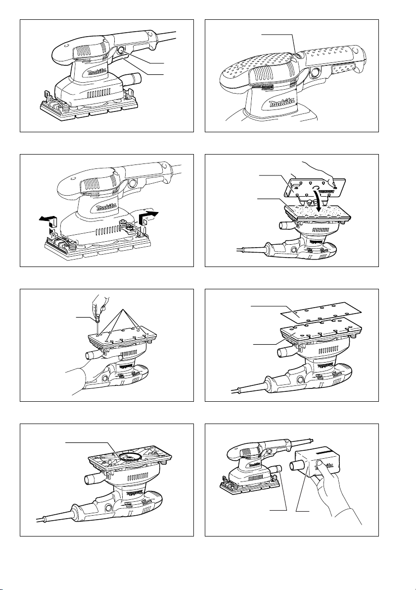
Switch action (Fig. 1)
CAUTION:
• Before plugging in the tool, always check to see that
the switch trigger actuates properly and returns to the
“OFF” position when released.
To start the tool, simply pull the switch trigger. Release
the switch trigger to stop.
For continuous operation, pull the switch trigger and then
push in the lock button.
To stop the tool from the locked position, pull the switch
trigger fully, then release it.
Speed adjusting dial (Fig. 2)
For BO3711 only
CAUTION:
• If the tool is operated continuously at low speeds, the
motor will get overloaded and heated up.
• The speed adjusting dial can be turned only as far as 5
and back to 1. Do not force it past 5 or 1, or the speed
adjusting function may no longer work.
The tool speed can be infinitely adjusted between 4,000
and 11,000 orbits per minute by turning the speed adjusting dial, which is marked 1 to 5. Higher speed is obtained
when the dial is turned in the direction of number 5, lower
speed is obtained when it is turned in the direction of
number 1. Adjust the desired tool speed for the kind of
work.
4
Page 5

ASSEMBLY
CAUTION:
• Always be sure that the tool is switched off and
unplugged before carrying out any work on the tool.
Installing or removing abrasive paper
For conventional type of abrasive paper with prepunched holes (standard equipment): (Fig. 3)
Press down the clamp lever (1 in the figure) and with the
clamp lever pressed down slide it toward the tool (2 in the
figure) and the clamper will be released.
Insert the paper end between a clamper and the pad
aligning the holes in the paper with those in pad. Then
return the clamp lever to the original position to secure it.
Release the other clamp lever by repeating the same
procedure.
While pulling abrasive paper to maintain the proper tension, insert and secure the other end of abrasive paper
between another clamper and the pad and return the
clamp lever to the original position.
To remove the paper, release the clamper as stated
above.
For conventional type of abrasive paper without prepunched holes (available on the market): (FIg. 4)
Press down the clamp lever 1 and with the clamp lever
pressed down slide it toward the tool 2 and the clamper
will be released.
Insert the paper end between a clamper and the pad
aligning the paper edges even and parallel with the sides
of the base. Then return the clamp lever to the original
position to secure it.
Release the other clamp lever by repeating the same
procedure.
While pulling abrasive paper to maintain the proper tension, insert and secure the other end of abrasive paper
between another clamper and the pad and return the
paper clamp lever to the original position.
Place the punch plate (optional accessory) over the
paper so that the guide of the punch plate is flush with
the sides of the base. Then press the punch plate to
make holes in the paper.
To remove the paper, release the clamper as stated
above.
For hook-and-loop type of abrasive paper with prepunched holes (optional accessory): (Fig. 5, 6 & 7)
CAUTION:
• Always use hook-and-loop type of abrasive papers.
Never use pressure-sensitive abrasive paper.
Remove the pad for the conventional type of abrasive
paper from the tool with a screwdriver. Install the pad for
the hook-and-loop type of abrasive paper (optional
accessory) on the tool. Tighten the screws firmly to
secure the pad.
Remove all dirt or foreign matter from the pad. Attach the
paper to the pad, aligning the holes in the paper with
those in the pad.
CAUTION:
• When removing the pad, O-ring may come out of the
tool. When this occurs, return the O-ring to the original
position and then install the pad.
Dust bag (optional accessory) (Fig. 8)
Attach the dust bag onto the dust spout. The dust spout
is tapered. When attaching the dust bag, push it onto the
dust spout firmly as far as it will go to prevent it from coming off during operation.
For the best results, empty the dust bag when it becomes
approximately half full, tapping it lightly to remove as
much dust as possible.
Installing filter (Optional accessory) (FIg. 9 & 10)
Make sure that the logo on the cardboard lip and the logo
on the dust box are on the same side, then install the filter by fitting the cardboard lip in the groove of each holding tab.
Make sure that the logo on the cardboard lip and the logo
on the dust nozzle are on the same side, then install the
dust nozzle on the dust box.
Removing dust box and filter (FIg. 11 & 12)
Remove the dust nozzle by pushing the two latches.
Remove the filter first by pinching the logo side of its
cardboard lip, then by pulling the cardboard lip downwards to move it out of the holding tab of the dust box.
OPERATION
Sanding operation (Fig. 13)
CAUTION:
• Never run the tool without the abrasive paper. You may
seriously damage the pad.
• Never force the tool. Excessive pressure may decrease
the sanding efficiency, damage the abrasive paper or
shorten tool life.
Hold the tool firmly. Turn the tool on and wait until it
attains full speed. Then gently place the tool on the workpiece surface. Keep the pad flush with the workpiece and
apply slight pressure on the tool.
MAINTENANCE
CAUTION:
• Always be sure that the tool is switched off and
unplugged before attempting to perform inspection or
maintenance.
To maintain product SAFETY and RELIABILITY, repairs,
carbon brush inspection and replacement, any other
maintenance or adjustment should be performed by Makita Authorized Service Centers, always using Makita
replacement parts.
5
Page 6

ACCESSORIES
CAUTION:
• These accessories or attachments are recommended
for use with your Makita tool specified in this manual.
The use of any other accessories or attachments might
present a risk of injury to persons. Only use accessory
or attachment for its stated purpose.
If you need any assistance for more details regarding
these accessories, ask your local Makita service center.
• Abrasive paper (with pre-punched holes)
• Hook-and-loop type of abrasive paper
• Punch plate
• Backing pad
(For use with hook-and-loop type of abrasive paper)
• Backing pad
(For use with conventional type of abrasive paper)
• Dust bag
• Dust box
• Filter
•Hose
6
Page 7

FRANÇAIS
Descriptif
1 Bouton de verrouillage
2 Gâchette
3 Cadran de réglage de la vitesse
4 Plaque perforée
5 Papier abrasif sans orifices
pré-perforés
SPÉCIFICATIONS
Modèle BO3710 BO3711
Dimensions du plateau ................................... 93 mm x 185 mm 93 mm x 185 mm
Dimensions du papier abrasif ........................ 93 mm x 228 mm 93 mm x 228 mm
Nombre d’oscillations par minute (min
Longueur totale .............................................. 253 mm 253 mm
Poids net ........................................................ 1,6 kg 1,6 kg
Catégorie de sécurité ..................................... /II /II
6Tournevis
7Vis
8 Papier abrasif
9 Plateau
10 Joint torique
11 Buse d’éjection poussière
–1
) ....... 11 000 4 000 – 11 000
12 Sac à poussière
13 Languette de retenue
14 Boîte à poussière
15 Raccord à poussière
16 Verrou
17 Raccord à poussière
• Étant donné l’évolution constante de notre programme
de recherche et de développement, les spécifications
contenues dans ce manuel sont sujettes à modification
sans préavis.
• Les spécifications peuvent varier suivant les pays.
• Poids selon la procédure EPTA 01/2003
Utilisations
L’outil est conçu pour le ponçage des grandes surfaces
de bois, de plastique et de métal, ainsi que des surfaces
peintes.
Alimentation
L’outil ne devra être raccordé qu’à une alimentation de la
même tension que celle qui figure sur la plaque signalétique, et il ne pourra fonctionner que sur un courant secteur monophasé. Réalisé avec une double isolation, il est
conforme à la réglementation européenne et peut de ce
fait être alimenté sans mise à la terre.
Consignes de sécurité
Pour votre propre sécurité, reportez-vous aux consignes
de sécurité qui accompagnent l’outil.
MISES EN GARDE DE SÉCURITÉ POUR
PONCEUSE
NE vous laissez PAS tromper (au fil d’une utilisation
répétée) par un sentiment d’aisance et de familiarité
avec le produit, en négligeant le respect rigoureux
des consignes de sécurité qui accompagnent le produit en question. Si vous n’utilisez pas cet outil électrique de façon sûre et adéquate, vous courez un
risque de blessure grave.
1. Utilisez toujours des lunettes de protection. Des
lunettes ordinaires ou de soleil NE sont PAS des
lunettes de protection.
2. Tenez l’outil fermement.
3. Ne vous éloignez pas de l’outil quand il fonc-
tionne. Ne faites fonctionner l’outil que lorsque
vous le tenez en main.
4. L’outil n’étant pas étanche, n’utilisez pas d’eau
sur la surface de travail.
5. Ventilez bien l’aire de travail quand vous effec-
tuez un ponçage.
GEB021-3
6. Certains matériaux contiennent des produits
chimiques qui peuvent être toxiques. Prenez les
précautions nécessaires pour éviter que la poussière dégagée ne soit inhalée ou n’entre en contact avec la peau. Suivez les consignes de
sécurité du fournisseur du matériau.
7. L’utilisation de cet outil pour poncer certains
types de produit, peinture et bois peut exposer
l’utilisateur à des poussières contenant des
substances dangereuses. Utilisez une protection
des voies respiratoires adéquate.
8. Avant l’utilisation, assurez-vous que le plateau
n’est ni fissuré ni cassé. Il y a risque de blessure
s’il est fissuré ou cassé.
CONSERVEZ CES INSTRUCTIONS.
AVERTISSEMENT :
La MAUVAISE UTILISATION de l’outil ou l’ignorance
des consignes de sécurité indiquées dans ce manuel
d’instructions peut entraîner une blessure grave.
DESCRIPTION DU FONCTIONNEMENT
ATTENTION :
• Assurez-vous toujours que l’outil est hors tension et
débranché avant de l’ajuster ou de vérifier son fonctionnement.
Interrupteur (Fig. 1)
ATTENTION :
• Avant de brancher l’outil, assurez-vous toujours que la
gâchette fonctionne correctement et qu’elle revient sur
la position “OFF” quand vous la relâchez.
Pour mettre l’outil en marche, tirez simplement sur la
gâchette. Pour l’arrêter, relâchez la gâchette.
Pour utiliser l’outil en continu, tirez sur la gâchette et
appuyez sur le bouton de verrouillage.
Pour arrêter l’outil quand il fonctionne en continu, tirez à
fond sur la gâchette puis relâchez-la.
7
Page 8

Cadran de réglage de la vitesse (Fig. 2)
Pour BO3711 uniquement
ATTENTION :
• Si l’outil est utilisé continuellement à vitesses lentes, le
moteur surchargera et chauffera.
• Le cadran de réglage de la vitesse ne peut être tourné
que jusqu’aux positions 5 et 1. Ne le forcez pas au-delà
de 5 ou en deçà de 1, autrement la fonction de réglage
de la vitesse risque de devenir inopérante.
La vitesse de l’outil peut être réglée sur toute valeur de
4 000 à 11 000 oscillations par minute en tournant le
cadran de réglage de la vitesse, gradué de 1 à 5. La
vitesse augmente lorsque l’on tourne le cadran vers le
numéro 5, et elle diminue lorsqu’on le tourne vers le
numéro 1. Réglez la vitesse de l’outil selon le type de travail à effectuer.
ASSEMBLAGE
ATTENTION :
• Avant d’effectuer toute intervention sur l’outil, assurezvous toujours qu’il est hors tension et débranché.
Pose ou dépose du papier abrasif
Pour le papier abrasif classique avec orifices préperforés (fourni en équipement standard) : (Fig. 3)
Abaissez le levier de serrage (1 sur l’illustration) et, tout
en le maintenant abaissé, faites-le glisser vers l’outil (2
sur l’illustration) pour libérer la pince.
Insérez l’extrémité du papier entre une pince et le plateau, en alignant les orifices du papier sur ceux du plateau. Remettez ensuite le levier de serrage sur sa
position initiale pour l’y fixer. Libérez l’autre levier de serrage en répétant la même procédure.
Tout en tirant sur le papier abrasif pour maintenir une
tension adéquate, insérez et fixez l’autre extrémité du
papier abrasif entre l’autre levier de serrage et le plateau,
puis remettez le levier de serrage sur sa position initiale.
Pour retirer le papier, libérez la pince comme indiqué cidessus.
Pour le papier abrasif classique sans orifices préperforés (disponible sur le marché) : (Fig. 4)
Abaissez le levier de serrage 1 et, tout en le maintenant
abaissé, faites-le glisser vers l’outil 2 pour libérer la
pince.
Insérez l’extrémité du papier entre une pince et le plateau en alignant les bords du papier de façon qu’ils
soient égaux et parallèles aux côtés de l’embase.
Remettez ensuite le levier de serrage sur sa position initiale pour l’y fixer.
Libérez l’autre levier de serrage en répétant la même
procédure.
Tout en tirant sur le papier abrasif pour maintenir une
tension adéquate, insérez et fixez l’autre extrémité du
papier abrasif entre l’autre levier de serrage et le plateau,
puis remettez le levier de serrage du papier sur sa position initiale.
Placez la plaque perforée (accessoire en option) sur le
papier de façon que le guide de la plaque perforée arrive
au ras des côtés de l’embase. Appuyez ensuite sur la
plaque perforée pour percer des orifices dans le papier.
Pour retirer le papier, libérez la pince comme indiqué cidessus.
Pour le papier abrasif auto-agrippant avec orifices
pré-perforés (accessoire en option) : (Fig. 5, 6 et 7)
ATTENTION :
• Utilisez toujours du papier abrasif auto-agrippant. N’utilisez jamais de papier abrasif à pression.
À l’aide d’un tournevis, retirez de l’outil le plateau pour
papier abrasif classique. Installez sur l’outil le plateau
pour papier abrasif auto-agrippant (accessoire en
option). Serrez les vis fermement pour fixer le plateau.
Retirez du plateau tout corps étranger et toute trace de
saleté. Fixez le papier au plateau, en alignant les orifices
du papier sur ceux de plateau.
ATTENTION :
• Lors du retrait du plateau, il se peut que le joint torique
se détache de l’outil. Si cela se produit, remettez le
joint torique sur sa position initiale, puis installez le plateau.
Sac à poussière (accessoire en option) (Fig. 8)
Fixez le sac à poussière sur la buse d’éjection poussière.
La buse d’éjection poussière est de forme conique. Pour
installer le sac à poussière, enfoncez-le à fond sur la
buse d’éjection poussière pour éviter qu’il ne se détache
pendant le travail.
Pour obtenir les meilleurs résultats, videz le sac à poussière lorsqu’il est environ à moitié plein, en le tapotant
légèrement pour retirer le plus de poussière possible.
Pose du filtre (accessoire en option) (Fig. 9 et 10)
Assurez-vous que le logo inscrit sur la lèvre de carton et
celui inscrit sur la boîte à poussière se trouvent du même
côté, puis installez le filtre en insérant la lèvre de carton
dans la rainure de chaque languette de retenue.
Assurez-vous que le logo inscrit sur la lèvre de carton et
celui inscrit sur le raccord à poussière se trouvent du
même côté, puis installez le raccord à poussière sur la
boîte à poussière.
Dépose de la boîte à poussière et du filtre (Fig. 11 et 12)
Retirez le raccord à poussière en poussant les deux verrous.
Retirez le filtre en le pinçant d’abord par le côté logo de
la lèvre de carton, puis en tirant la lèvre de carton vers le
bas pour la faire sortir de la languette de retenu de la
boîte à poussière.
UTILISATION
Ponçage (Fig. 13)
ATTENTION :
• Ne faites jamais fonctionner l’outil sans papier abrasif.
Vous pourriez endommager gravement le plateau.
• Ne forcez jamais l’outil. Une pression trop grande peut
causer une diminution de l’efficacité du ponçage,
endommager le papier abrasif ou réduire la durée de
service de l’outil.
Tenez l’outil fermement. Mettez l’outil sous tension et
attendez qu’il ait atteint sa pleine vitesse. Posez ensuite
doucement l’outil sur la surface de la pièce à travailler.
Maintenez le plateau parallèle à la pièce à travailler et
appliquez une légère pression sur l’outil.
8
Page 9

ENTRETIEN
ATTENTION :
• Assurez-vous toujours que l’outil est hors tension et
débranché avant d’y effectuer tout travail d’inspection
ou d’entretien.
Pour maintenir la SÉCURITÉ et la FIABILITÉ du produit,
les réparations, l’inspection et le remplacement des charbons, et tout autre travail d’entretien ou de réglage doivent être effectués dans un centre de service Makita
agréé ou un centre de service de l’usine Makita, exclusivement avec des pièces de rechange Makita.
ACCESSOIRES
ATT EN TI ON :
• Ces accessoires ou pièces complémentaires sont
recommandés pour l’utilisation avec l’outil Makita spécifié dans ce manuel. L’utilisation de tout autre accessoire ou pièce peut comporter un risque de blessure.
N’utilisez les accessoires ou pièces qu’aux fins mentionnées dans le présent manuel.
Si vous désirez obtenir plus de détails concernant ces
accessoires, veuillez contacter le centre de service
après-vente Makita le plus près.
• Papier abrasif (avec orifices pré-perforés)
• Pour le papier abrasif auto-agrippant
• Plaque perforée
• Plateau de support (Pour papier abrasif auto-agrippant)
• Plateau de support (Pour papier abrasif classique)
• Sac à poussière
• Boîte à poussière
• Filtre
• Tuyau
9
Page 10

DEUTSCH
Übersicht
1 Arretierknopf
2 Ein-Aus-Schalter
3 Drehzahl-Stellrad
4 Lochungsplatte
5 Schleifpapier ohne
vorgestanzte Löcher
TECHNISCHE DATEN
Modell BO3710 BO3711
Schleiftellergröße ............................................93 mm x 185 mm 93 mm x 185 mm
Schleifpapiergröße ..........................................93 mm x 228 mm 93 mm x 228 mm
Umdrehungen pro Minute (min
Gesamtlänge ...................................................253 mm 253 mm
Nettogewicht ...................................................1,6 kg 1,6 kg
Sicherheitsklasse ............................................ /II /II
–1
6 Schraubendreher
7Schraube
8 Schleifpapier
9 Schleifteller
10 O-Ring
11 Absaugstutzen
) ...................11 000 4 000 – 11 000
12 Staubsack
13 Haltenase
14 Staubsammelbehälter
15 Ansaugstutzen
16 Klinke
17 Ansaugstutzen
• Wir behalten uns vor, Änderungen im Zuge der Entwicklung und des technischen Fortschritts ohne vorherige Ankündigung vorzunehmen.
• Die technischen Daten können von Land zu Land
abweichen.
• Gewicht nach EPTA-Verfahren 01/2003
Vorgesehene Verwendung
Das Werkzeug ist für das Schleifen großer Flächen aus
Holz, Kunststoff und Metall sowie lackierter Flächen vorgesehen.
Netzanschluß
Die Maschine darf nur an die auf dem Typenschild angegebene Netzspannung angeschlossen werden und
arbeitet nur mit Einphasen-Wechselspannung. Sie ist
entsprechend den Europäischen Richtlinien doppelt
schutzisoliert und kann daher auch an Steckdosen ohne
Erdanschluß betrieben werden.
Sicherheitshinweise
Lesen und beachten Sie diese Hinweise, bevor Sie das
Gerät benutzen.
SICHERHEITSWARNUNGEN FÜR SCHLEIFER
Lassen Sie sich NICHT durch Bequemlichkeit oder
Vertrautheit mit dem Produkt (durch wiederholten
Gebrauch erworben) von der strikten Einhaltung der
Sicherheitsregeln für das vorliegende Produkt abhalten. Wenn Sie dieses Elektrowerkzeug auf unsichere
oder unsachgemäße Weise benutzen, können Sie
schwere Verletzungen erleiden.
1. Tragen Sie stets eine Sicherheits- oder Schutz-
brille. Eine gewöhnliche Brille oder Sonnenbrille
ist KEIN Ersatz für eine Sicherheitsbrille.
2. Halten Sie die Maschine mit festem Griff.
3. Lassen Sie die Maschine nicht unbeaufsichtigt
laufen. Benutzen Sie die Maschine nur im handgeführten Einsatz.
4. Diese Maschine ist nicht wasserdicht. Benetzen
Sie daher die Bearbeitungsfläche nicht mit Wasser.
5. Sorgen Sie für ausreichende Belüftung des
Arbeitsplatzes beim Schleifen.
GEB021-3
6. Manche Materialien können giftige Chemikalien
enthalten. Treffen Sie Vorsichtsmaßnahmen, um
das Einatmen von Arbeitsstaub und Hautkontakt
zu verhüten. Befolgen Sie die Sicherheitsdaten
des Materialherstellers.
7. Der Gebrauch dieses Werkzeugs zum Schleifen
bestimmter Produkte, Lacke und Holz kann den
Benutzer Staub aussetzen, der gefährliche Substanzen enthält. Verwenden Sie einen geeigneten Atemschutz.
8. Vergewissern Sie sich vor dem Gebrauch, dass
der Schleifteller keine Risse oder Brüche aufweist. Risse oder Brüche können Verletzungen
verursachen.
BEWAHREN SIE DIESE HINWEISE
SORG F ÄLTIG AUF.
WARNUNG:
MISSBRAUCH oder Missachtung der Sicherheitsvorschriften in dieser Anleitung können schwere Verletzungen verursachen.
FUNKTIONSBESCHREIBUNG
VORSICHT:
• Vergewissern Sie sich vor jeder Einstellung oder Funk-
tionsprüfung der Maschine stets, dass sie ausgeschaltet und vom Stromnetz getrennt ist.
Schalterfunktion (Abb. 1)
VORSICHT:
• Vergewissern Sie sich vor dem Anschließen der
Maschine an das Stromnetz stets, daß der Ein-AusSchalter ordnungsgemäß funktioniert und beim Loslassen in die AUS-Stellung zurückkehrt.
Zum Einschalten der Maschine drücken Sie einfach den
Ein-Aus-Schalter. Zum Ausschalten lassen Sie den EinAus-Schalter los.
Für Dauerbetrieb betätigen Sie den Ein-Aus-Schalter
und drücken dann den Arretierknopf hinein.
Zum Ausrasten des Arretierknopfes drücken Sie den EinAus-Schalter bis zum Anschlag hinein und lassen ihn
dann los.
10
Page 11

Drehzahl-Stellrad (Abb. 2)
Nur für BO3711
VORSICHT:
• Wird die Maschine im Dauerbetrieb mit niedriger Drehzahl betrieben, kommt es zu Überlastung und Überhitzung des Motors.
• Das Drehzahl-Stellrad lässt sich nur bis 5 und zurück
auf 1 drehen. Wird es gewaltsam über 5 oder 1 hinaus
gedreht, lässt sich die Drehzahl möglicherweise nicht
mehr einstellen.
Die Drehzahl der Maschine kann durch Drehen des mit 1
bis 5 markierten Drehzahl-Stellrads stufenlos zwischen
4 000 und 11 000 Umdrehungen pro Minute eingestellt
werden. Durch Drehen des Stellrads in Richtung der
Nummer 5 wird die Drehzahl erhöht, während sie durch
Drehen in Richtung 1 verringert wird. Stellen Sie die
Maschinendrehzahl je nach Art der Arbeit wunschgemäß
ein.
MONTAGE
VORSICHT:
• Vergewissern Sie sich vor der Ausführung von Arbeiten
an der Maschine stets, dass sie ausgeschaltet und vom
Stromnetz getrennt ist.
Anbringen oder Abnehmen des Schleifpapiers
Für herkömmliches Schleifpapier mit vorgestanzten
Löchern (Standardausstattung): (Abb. 3)
Den Spannhebel (1 in der Abbildung) niederdrücken und
in diesem Zustand auf die Maschine zu schieben (2 in
der Abbildung), so dass die Klemme gelöst wird.
Das Papierende zwischen eine Klemme und den Schleifteller einführen, so dass die Löcher im Papier sich mit
denen im Schleifteller decken. Dann den Spannhebel zur
Sicherung auf die Ausgangsstellung zurückstellen.
Den anderen Spannhebel durch Wiederholen des gleichen Vorgangs lösen.
Während das Schleifpapier gestrafft wird, um die korrekte Spannung beizubehalten, das andere Ende des
Schleifpapiers zwischen die andere Klemme und den
Schleifteller einführen und sichern, und den Spannhebel
auf die Ausgangsstellung zurückstellen.
Zum Entfernen des Papiers die Klemme so lösen, wie
oben beschrieben.
Für herkömmliches Schleifpapier ohne vorgestanzte
Löcher (im Fachhandel erhältlich): (Abb. 4)
Den Spannhebel 1 niederdrücken und in diesem Zustand
auf die Maschine 2 zu schieben, so dass die Klemme
gelöst wird.
Das Papierende zwischen eine Klemme und den Schleifteller einführen, und dabei die Papierkanten gleichmäßig
und parallel auf die Seitenkanten der Grundplatte ausrichten. Dann den Spannhebel zur Sicherung auf die
Ausgangsstellung zurückstellen.
Den anderen Spannhebel durch Wiederholen des gleichen Vorgangs lösen.
Während das Schleifpapier gestrafft wird, um die korrekte Spannung beizubehalten, das andere Ende des
Schleifpapiers zwischen die andere Klemme und den
Schleifteller einführen und sichern, und den Spannhebel
auf die Ausgangsstellung zurückstellen.
Die Lochungsplatte (Sonderzubehör) so auf das Papier
setzen, dass ihre Führung bündig mit den Seiten der
Grundplatte abschließt. Dann die Lochungsplatte
andrücken, um Löcher in das Schleifpapier zu stanzen.
Zum Entfernen des Papiers die Klemme so lösen, wie
oben beschrieben.
Für Klett-Schleifpapier mit vorgestanzten Löchern
(Sonderzubehör): (Abb. 5, 6 und 7)
VORSICHT:
• Verwenden Sie stets Klett-Schleifpapier. Verwenden
Sie keinesfalls druckempfindliches Schleifpapier.
Den Schleifteller für herkömmliches Schleifpapier mit
einem Schraubendreher von der Maschine abmontieren.
Den Schleifteller für Klett-Schleifpapier (Sonderzubehör)
an der Maschine anbringen. Die Schrauben zur Sicherung des Schleiftellers fest anziehen.
Den Schleifteller von jeglichem Schmutz oder Fremdkörpern säubern. Das Papier am Schleifteller anbringen, so
dass sich die Löcher im Papier mit denen im Schleifteller
decken.
VORSICHT:
• Beim Abnehmen des Schleiftellers kann der O-Ring
aus der Maschine herausfallen. Falls dies eintritt, den
O-Ring wieder in die Ausgangsstellung bringen, und
dann den Schleifteller montieren
Staubsack (Sonderzubehör) (Abb. 8)
Befestigen Sie den Staubsack am Absaugstutzen. Der
Absaugstutzen ist konisch. Schieben Sie den Staubsack
zum Anbringen bis zum Anschlag fest auf den Absaugstutzen, damit er sich während des Betriebs nicht löst.
Um beste Ergebnisse zu erzielen, empfiehlt es sich, den
Staubsack zu entleeren, wenn er etwa halb voll ist, wobei
durch leichtes Abklopfen möglichst viel Staub gelöst werden sollte.
Anbringen des Filters (Sonderzubehör) (Abb. 9
und 10)
Sicherstellen, dass das Logo auf der Kartonlippe und
das Logo auf dem Staubsammelbehälter auf derselben
Seite liegen, dann den Filter anbringen, indem die Kartonlippe in die Nut jeder Haltenase eingepasst wird.
Sicherstellen, dass das Logo auf der Kartonlippe und
das Logo am Ansaugstutzen auf derselben Seite liegen,
dann den Ansaugstutzen am Staubsammelbehälter
anbringen.
Entfernen von Staubsammelbehälter und Filter (Abb. 11
und 12)
Den Ansaugstutzen durch Hineindrücken der zwei Klinken abnehmen.
Den Filter zuerst entfernen, indem die Logo-Seite seiner
Kartonlippe zusammengedrückt und dann die Kartonlippe nach unten gezogen wird, um sie aus der Haltenase des Staubsammelbehälters herauszuziehen.
11
Page 12

BETRIEB
Schleifbetrieb (Abb. 13)
VORS ICHT:
• Benutzen Sie die Maschine niemals ohne Schleifpapier. Der Schleifteller könnte sonst schwer beschädigt
werden.
• Niemals gewaltsam auf die Maschine drücken. Übermäßiger Druck kann die Schleifleistung verschlechtern,
das Schleifpapier beschädigen oder die Lebensdauer
der Maschine verkürzen.
Halten Sie die Maschine mit festem Griff. Schalten Sie
die Maschine ein und warten Sie, bis sie ihre volle Drehzahl erreicht. Setzen Sie dann die Maschine sachte auf
die Werkstück-Oberfläche. Halten Sie den Schleifteller
flach gegen das Werkstück, und üben Sie leichten Druck
auf die Maschine aus.
WARTUNG
VORS ICHT:
• Denken Sie vor der Durchführung von Überprüfungen
oder Wartungsarbeiten stets daran, die Maschine auszuschalten und vom Stromnetz zu trennen.
Um die SICHERHEIT und ZUVERLÄSSIGKEIT dieses
Produkts aufrechtzuerhalten, sollten Reparaturen, Überprüfung und Austausch der Kohlebürsten und andere
Wartungs- oder Einstellarbeiten nur von Makita-Vertragswerkstätten oder Makita-Kundendienstzentren unter ausschließlicher Verwendung von MakitaOriginalersatzteilen ausgeführt werden.
ZUBEHÖR
VORS ICHT:
• Die folgenden Zubehörteile oder Vorrichtungen werden
für den Einsatz mit der in dieser Anleitung beschriebenen Makita-Maschine empfohlen. Die Verwendung
anderer Zubehörteile oder Vorrichtungen kann eine
Verletzungsgefahr darstellen. Verwenden Sie Zubehörteile oder Vorrichtungen nur für ihren vorgesehenen
Zweck.
Wenn Sie weitere Einzelheiten bezüglich dieser Zubehörteile benötigen, wenden Sie sich bitte an Ihre MakitaKundendienstzentrum.
• Schleifpapier (mit vorgestanzten Löchern)
• Klett-Schleifpapier
• Lochungsplatte
• Grundplatte
(Für Einsatz mit Klett-Schleifpapier)
• Grundplatte
(Für Einsatz mit herkömmlichem Schleifpapier)
•Staubsack
• Staubsammelbehälter
• Filter
• Schlauc
12
Page 13

ITALIANO
Visione generale
1 Bottone di bloccaggio
2 Interruttore
3 Ghiera di regolazione velocità
4 Piastra di punzonatura
5 Carta abrasiva senza fori
pre-punzonati
DATI TECNICI
Modello BO3710 BO3711
Dimensioni tampone....................................... 93 mm x 185 mm 93 mm x 185 mm
Dimensioni carta abrasiva ............................. 93 mm x 228 mm 93 mm x 228 mm
Giri/min. (min
Lunghezza totale ............................................ 253 mm 253 mm
Peso netto ...................................................... 1,6 kg 1,6 kg
Classe di sicurezza......................................... /II /II
–1
).............................................. 11.000 4.000 – 11.000
6 Cacciavite
7Vite
8 Carta abrasiva
9 Tampone
10 Anello di tenuta toroidale
11 Boccaglio polvere
12 Sacchetto polvere
13 Appendice di bloccaggio
14 Scatola della polvere
15 Bocchettone polvere
16 Gancio
17 Bocchettone polvere
• Per il nostro programma di ricerca e sviluppo continui, i
dati tecnici sono soggetti a modifiche senza preavviso.
• I dati tecnici potrebbero differire a seconda del paese di
destinazione del modello.
• Peso in base alla procedura EPTA 01/2003
Utilizzo specifico dell’utensile
Questo utensile serve alla smerigliatura di grandi superfici di legno, plastica e metallo, come pure quelle verniciate.
Alimentazione
L’utensile deve essere collegato ad una presa di corrente
con la stessa tensione indicata sulla targhetta del nome,
e può funzionare soltanto con la corrente alternata
monofase. Esso ha un doppio isolamento in osservanza
alle norme europee, per cui può essere usato con le
prese di corrente sprovviste della messa a terra.
Consigli per la sicurezza
Per la vostra sicurezza, riferitevi alle accluse istruzioni
per la sicurezza.
AVVERTIMENTI PER LA SICUREZZA DELLA
LEVIGATRICE
NON lasciare che comodità o la familiarità d’utilizzo
con il prodotto (acquisita con l’uso ripetuto) sostituisca la stretta osservanza delle norme di sicurezza.
Se si usa questo utensile elettrico in modo insicuro o
sbagliato, c’è pericolo di seri infortuni.
1. Usare sempre occhiali di sicurezza o occhialoni.
I normali occhiali o gli occhiali da sole NON
sono occhiali di sicurezza.
2. Tenere saldamente l’utensile.
3. Non posare l’utensile mentre gira. Farlo funzio-
nare soltanto tenendolo in mano.
4. Questo utensile non è a prova d’acqua, per cui
non usare acqua sulla superficie del pezzo.
5. Ventilare adeguatamente l’area di lavoro durante
le operazioni di smerigliatura.
6. Alcuni materiali potrebbero contenere sostanze
chimiche tossiche. Prendere le dovute precauzioni per evitare che vengano inalate o entrino in
contatto con la pelle. Attenersi alle indicazioni di
sicurezza fornite dal produttore del materiale.
GEB021-3
7. L’utilizzo di questo utensile per smerigliare
alcuni prodotti, vernici e legni potrebbe esporre
l’utente a polvere contenente sostanze pericolose. Usare le appropriate protezioni delle vie
respiratorie.
8. Accertarsi che sul tampone non ci siano crepe e
che non sia rotto prima di usarlo. Un tampone
con crepe o rotto potrebbe causare infortuni.
CONSERVATE QUESTE ISTRUZIONI.
AVVERTENZA:
L’utilizzo SBAGLIATO o la mancata osservanza delle
norme di sicurezza di questo manuale di istruzioni
potrebbe causare lesioni serie.
DESCRIZIONE FUNZIONALE
ATTENZIONE:
• Accertarsi sempre che l’utensile sia spento e staccato
dalla presa di corrente prima di regolarlo o di controllare il suo funzionamento.
Azionamento dell’interruttore (Fig. 1)
ATTENZIONE:
• Prima di collegare l’utensile alla presa di corrente, con-
trollare sempre che l’interruttore funzioni correttamente
e torni sulla posizione “OFF” quando viene rilasciato.
Per avviare l’utensile, schiacciare semplicemente l’interruttore. Rilasciare l’interruttore per fermarlo.
Per il funzionamento continuo, schiacciare l’interruttore e
spingere dentro il bottone di bloccaggio.
Per fermare l’utensile dalla posizione di bloccaggio,
schiacciare completamente l’interruttore e rilasciarlo.
Ghiera di regolazione velocità (Fig. 2)
Per il modello BO3711 soltanto
ATTENZIONE:
• Se si fa funzionare l’utensile continuamente alle basse
velocità, si causa il sovraccarico e il surriscldamento
del motore.
• La ghiera di regolazione della velocità può essere
girata soltanto fino a 5 e indietro fino a 1. Essa non
deve essere forzata oltre il 5 o l’1, perché altrimenti la
funzione di regolazione della velocità potrebbe non
essere più utilizzabile.
13
Page 14

La velocità dell’utensile può essere variata infinitamente
tra i 4.000 e i 11.000 giri/min. girando il pomello di regolazione della velocità, che reca i contrassegni da 1 a 5. Si
ottiene una velocità maggiore girando la ghiera nella
direzione del numero 5, e una velocità minore girando la
ghiera nella direzione del numero 1. Regolare la velocità
dell’utensile desiderata appropriata al tipo di lavoro da
eseguire.
MONTAGGIO
ATTENZIONE:
• Accertarsi sempre che l’utensile sia spento e staccato
dalla presa di corrente prima di qualsiasi intervento su
di esso.
Installazione o rimozione della carta abrasiva
Per il tipo convenzionale di carta abrasiva con fori
pre-punzonati (attrezzatura standard): (Fig. 3)
Premere giù la leva di bloccaggio (1 nella illustrazione) e,
con la leva di bloccaggio premuta giù, spingerla verso
l’utensile (2 nella illustrazione) per rilasciare il dispositivo
di bloccaggio.
Inserire l’estremità della carta tra un dispositivo di bloccaggio e il tampone allineando i fori della carta con quelli
del tampone. Rimettere poi la leva di bloccaggio sulla
sua posizione originale per fissarla.
Rilasciare l’altra leva di bloccaggio ripetendo lo stesso
procedimento.
Tirando la carta abrasiva per mantenere la tensione corretta, inserire e fissare l’altra estremità della carta abrasiva tra un altro dispositivo di bloccaggio e il tampone, e
rimettere la leva di bloccaggio sulla sua posizione originale.
Per rimuovere la carta, rilasciare il dispositivo di bloccaggio come descritto sopra.
Per il tipo convenzionale di carta abrasiva senza fori
pre-punzonati (disponibile in commercio): (Fig. 4)
Premere giù la leva di bloccaggio 1 e, con la leva di bloccaggio premuta giù, spingerla verso l’utensile 2 per rilasciare il dispositivo di bloccaggio.
Inserire l’estremità della carta tra un dispositivo di bloccaggio e il tampone allineando i bordi della carta a paro e
paralleli con i lati della base. Rimettere poi la leva di bloccaggio sulla sua posizione originale per fissarla.
Rilasciare l’altra leva di bloccaggio ripetendo lo stesso
procedimento.
Tirando la carta abrasiva per mantenere la tensione corretta, inserire e fissare l’altra estremità della carta abrasiva tra un altro dispositivo di bloccaggio e il tampone, e
rimettere la leva di bloccaggio sulla sua posizione originale.
Mettere la piastra di punzonatura (accessorio opzionale)
sopra la carta in modo che la guida della piastra di punzonatura sia a livello con i lati della base. Premere poi la
piastra di punzonatura per praticare i fori nella carta.
Per rimuovere la carta, rilasciare il dispositivo di bloccaggio come descritto sopra.
Per il tipo di carta abrasiva ad aggancio e avvolgimento con fori pre-punzonati (accessorio opzionale):
(Figg. 5, 6 e 7)
ATTENZIONE:
• Usare sempre i tipi di carta abrasiva ad aggancio e
avvolgimento. Mai usare la carta abrasiva sensibile alle
pressioni.
Rimuovere il tampone per il tipo di carta abrasiva convenzionale dall’utensile usando un cacciavite. Installare il
tampone per il tipo di carta abrasiva ad aggancio e avvolgimento (accessorio opzionale) sull’utensile. Stringere
saldamente le viti per fissare il tampone.
Togliere tutto lo sporco o le sostanze estranee dal tampone. Attaccare la carta al tampone allineando i fori della
carta con quelli del tampone.
ATTENZIONE:
• Quando si rimuove il tampone, l’anello di tenuta toroidale potrebbe fuoriuscire dall’utensile. In tal caso,
rimettere l’anello di tenuta toroidale nella sua posizione
originale e installare il tampone.
Sacchetto polvere (accessorio opzionale) (Fig. 8)
Attaccare il sacchetto della polvere al boccaglio della polvere. Il boccaglio della polvere è rastremato. Per attaccare il sacchetto della polvere, spingerlo saldamente nel
boccaglio finché non può andare più oltre per evitare che
si stacchi durante il lavoro.
Per ottenere i risultati migliori, svuotare il sacchetto della
polvere quando diventa quasi pieno a metà dandogli dei
leggeri colpetti per rimuovere quanta più polvere possibile.
Installazione del filtro (Accessorio opzionale)
(Figg. 9 e 10)
Accertarsi che il logo sul labbro della scatola di cartone e
il logo sul sacchetto della polvere si trovino sullo stesso
lato, e installare poi il filtro montando il labbro della scatola di cartone nella scanalatura di ciascuna appendice
di bloccaggio.
Accertarsi che il logo sul labbro della scatola di cartone e
il logo sul bocchettone della polvere si trovino sullo
stesso lato, e installare poi il bocchettone della polvere
sulla scatola della polvere.
Rimozione della scatola della polvere e del filtro
(Figg. 11 e 12)
Rimuovere il bocchettone della polvere spingendo i due
ganci.
Rimuovere prima il filtro stringendo il lato del logo del suo
labbro della scatola di cartone e tirando poi in giù il labbro della scatola di cartone per spostarlo fuori dalla
appendice di bloccaggio della scatola della polvere.
OPERAZIONI
Operazione di smerigliatura (Fig. 13)
ATTENZIONE:
• L’utensile non deve mai essere fatto funzionare senza
la carta abrasiva. Si potrebbe danneggiare seriamente
il tampone.
• Non forzare mai l’utensile. Una pressione eccessiva
potrebbe ridurre l’efficienza di smerigliatura, danneggiare la carta abrasiva o accorciare la vita di servizio
dell’utensile.
Tenere saldamente l’utensile. Accendere l’utensile e
aspettare finché raggiunge la sua velocità massima.
Appoggiare poi delicatamente l’utensile sulla superficie
del pezzo. Mantenere il tampone a raso sul pezzo e
applicare una leggera pressione sull’utensile.
14
Page 15

MANUTENZIONE
ATTENZIONE:
• Accertarsi sempre che l’utensile sia spento e staccato
dalla presa di corrente prima di qualsiasi intervento di
ispezione o di manutenzione.
Per preservare la SICUREZZA e l’AFFIDABILITÀ del
prodotto, le riparazioni, l’ispezione e la sostituzione della
spazzola di carbone o qualsiasi altra manutenzione e
regolazione devono essere eseguite da un Centro Assistenza Makita autorizzato usando sempre ricambi
Makita.
ACCESSORI
ATTENZIONE:
• Per l’utensile specificato in questo manuale, si consigliano questi accessori o ricambi. L’utilizzo di altri
accessori o ricambi può costituire un pericolo di lesioni.
Usare soltanto gli accessori o ricambi specificati per il
loro utilizzo.
Per maggiori dettagli e l’assistenza, rivolgersi al Centro
Assistenza Makita locale.
• Carta abrasiva (con fori pre-punzonati)
• Tipi di carta abrasiva ad aggancio e avvolgimento
• Piastra di punzonatura
• Cuscinetto di rinforzo
(Per l’uso con il tipo di carta abrasiva ad aggancio e
avvolgimento)
• Cuscinetto di rinforzo
(Per l’uso con il tipo di carta abrasiva convenzionale)
• Sacchetto polvere
• Scatola della polvere
• Filtro
• Manicotto
15
Page 16

NEDERLANDS
Verklaring van algemene gegevens
1 Vergrendelknop
2 Trekschakelaar
3 Snelheidsregelaar
4 Perforeerplaat
5 Schuurpapier zonder
voorgeperforeerde gaten
TECHNISCHE GEGEVENS
Model BO3710 BO3711
Afmetingen schuurzool ...................................93 mm x 185 mm 93 mm x 185 mm
Afmetingen schuurpapier ................................93 mm x 228 mm 93 mm x 228 mm
Omwentelingen per minuut (min
Totale lengte ....................................................253 mm 253 mm
Netto gewicht ..................................................1,6 kg 1,6 kg
Veiligheidsklasse............................................. /II /II
6 Schroevendraaier
7Schroef
8 Schuurpapier
9 Schuurzool
10 O-ring
11 Stofuitwerpmond
–1
).................11 000 4 000 – 11 000
12 Stofzak
13 Bevestigingslip
14 Stofvanger
15 Stofafzuigaansluitmond
16 Vergrendeling
17 Stofafzuigaansluitmond
• In verband met ononderbroken research en ontwikkeling behouden wij ons het recht voor bovenstaande
technische gegevens te wijzigen zonder voorafgaande
kennisgeving.
• De technische gegevens kunnen van land tot land verschillen.
• Gewicht volgens de EPTA-procedure 01/2003
Doeleinden van gebruik
Dit gereedschap is bedoeld voor het schuren van grote
oppervlakken van hout-, kunststof- en metaalmaterialen,
en ook geschilderde oppervlakken.
Stroomvoorziening
Het gereedschap mag alleen worden aangesloten op
een stroombron van hetzelfde voltage als aangegeven op
de naamplaat, en kan alleen op enkel-fase wisselstroom
worden gebruikt. Het gereedschap is dubbel-geïsoleerd
volgens de Europese standaard en kan derhalve ook op
een niet-geaard stopcontact worden aangesloten.
Veiligheidswenken
Voor uw veiligheid dient u de bijgevoegde Veiligheidsvoorschriften nauwkeurig op te volgen.
VEILIGHEIDSWAARSCHUWINGEN SPECIFIEK
VOOR VLAKSCHUURMACHINES
Laat u NIET misleiden door een vals gevoel van comfort en bekendheid met het gereedschap (na veelvuldig gebruik) en neem alle veiligheidsvoorschriften
van het betreffende gereedschap altijd strikt in acht.
Bij onveilig of verkeerd gebruik van het elektrisch
gereedschap, bestaat de kans op ernstig persoonlijk
letsel.
1. Draag altijd een veiligheidsbril. Een gewone bril
of een zonnebril is GEEN veiligheidsbril.
2. Houd het gereedschap stevig vast.
3. Schakel het gereedschap altijd uit als u weg
moet. Schakel het gereedschap alleen in wanneer u het vasthoudt.
4. Dit gereedschap is niet waterdicht. Besprenkel
derhalve het oppervlak van het werkstuk niet
met water.
5. Zorg dat uw werkplaats goed geventileerd is
wanneer u gaat schuren.
GEB021-3
6. Sommige materialen bevatten chemicaliën die
giftig kunnen zijn. Pas op dat u het werkstof van
dergelijke materialen niet inademt en vermijd
contact met de huid. Volg de veiligheidsvoorschriften van de leverancier van het materiaal
op.
7. Als dit gereedschap wordt gebruikt voor het
schuren van bepaalde producten, verflagen en
hout, kan de gebruiker worden blootgesteld aan
stof waarin gevaarlijke bestanddelen zitten.
Gebruik geschikte ademhalingbeschermingsapparatuur.
8. Controleer voor het gebruik of de schuurzool
niet gescheurd of gebroken is. Een gescheurde
of gebroken schuurzool kan persoonlijk letsel
veroorzaken.
BEWAAR DEZE VOORSCHRIFTEN.
WAARSCHUWING:
VERKEERD GEBRUIK of het niet naleven van de vei-
ligheidsvoorschriften in deze gebruiksaanwijzing
kan leiden tot ernstige verwondingen.
BESCHRIJVING VAN DE FUNCTIES
LET OP:
• Zorg altijd dat het gereedschap is uitgeschakeld en zijn
stekker uit het stopcontact is verwijderd voordat u functies op het gereedschap afstelt of controleert.
Werking van de trekschakelaar (Fig. 1)
LET OP:
• Alvorens de stekker van het gereedschap op een stop-
contact aan te sluiten, dient u altijd te controleren of de
trekschakelaar behoorlijk werkt en bij loslaten naar de
“OFF” positie terugkeert.
Om het gereedschap te starten, drukt u gewoon de trekschakelaar in. Laat de trekschakelaar los om te stoppen.
Om continu te werken, drukt u eerst de trekschakelaar en
daarna de vergrendelknop in.
Om het gereedschap vanuit deze vergrendelde stand te
stoppen, drukt u de trekschakelaar volledig in en dan laat
u hem los.
16
Page 17

Snelheidsregelaar (Fig. 2)
Alleen voor BO3711
LET OP:
• Als het gereedschap continu op lage snelheid wordt
gebruikt, zal de motor overbelast en oververhit raken.
• U kunt de snelheidsregelaar alleen tot aan het cijfer 5
draaien en terug naar 1. Forceer de snelheidsregelaar
niet voorbij de 5 of de 1 omdat de snelheidsregeling
daardoor onklaar raakt.
Door de snelheidsregelaar te verdraaien kunt u de snelheid van de cirkelzaag traploos instellen tussen 4 000 en
11 000 omwentelingen per minuut. Als u de snelheidsregelaar in de richting van stand 5 draait, wordt de
snelheid van het gereedschap hoger. Als u in de richting
van stand 1 draait, wordt de snelheid lager. Stel de snelheid van het gereedschap in aan de hand van de soort
werkzaamheden.
INEENZETTEN
LET OP:
• Zorg altijd dat het gereedschap is uitgeschakeld en zijn
stekker uit het stopcontact is verwijderd alvorens enig
werk aan het gereedschap uit te voeren.
Het schuurpapier aanbrengen en verwijderen
Conventioneel schuurpapier met voorgeperforeerde
gaten (standaard toebehoren): (Fig. 3)
Houd de klemhendel (1 in de afbeelding) omlaag gedrukt
en schuif deze in de richting van het gereedschap (2 in
de afbeelding) zodat de schuurpapierklem wordt geopend.
Steek het uiteinde van het schuurpapier tussen de
schuurpapierklem en de schuurzool, en lijn de gaten in
het schuurpapier uit met de gaten in de schuurzool. Zet
daarna de klemhendel terug in zijn oorspronkelijke stand
om het schuurpapier vast te klemmen.
Zet de andere schuurpapierklem open volgens dezelfde
procedure.
Trek aan het schuurpapier om de juiste spanning te verkrijgen, steek het andere uiteinde van het schuurpapier
tussen de schuurpapierklem en de schuurzool, en zet de
klemhendel terug in zijn oorspronkelijke stand.
Om het schuurpapier te verwijderen, zet u de schuurpapierklemmen open zoals hierboven beschreven.
Conventioneel schuurpapier zonder voorgeperforeerde gaten (verkrijgbaar in de handel): (Fig. 4)
Houd de klemhendel (1) omlaag gedrukt en schuif deze
in de richting van het gereedschap (2) zodat de schuurpapierklem wordt geopend.
Steek het uiteinde van het schuurpapier tussen de
schuurpapierklem en de schuurzool, en lijn de rand van
het schuurpapier uit met de zijkant van de schuurzool.
Zet daarna de klemhendel terug in zijn oorspronkelijke
stand om het schuurpapier vast te klemmen.
Zet de andere schuurpapierklem open volgens dezelfde
procedure.
Trek aan het schuurpapier om de juiste spanning te verkrijgen, steek het andere uiteinde van het schuurpapier
tussen de schuurpapierklem en de schuurzool, en zet de
klemhendel terug in zijn oorspronkelijke stand.
Plaats de perforeerplaat (los verkrijgbaar) zodanig op het
schuurpapier dat de geleider van de perforeerplaat
samenvalt met de zijkanten van de schuurzool. Druk vervolgens op de perforeerplaat om gaten in het schuurpapier te maken.
Om het schuurpapier te verwijderen, zet u de schuurpapierklemmen open zoals hierboven beschreven.
Klittenbandschuurpapier met voorgeperforeerde
gaten (los verkrijgbaar): (Fig. 5, 6 en 7)
LET OP:
• Gebruik altijd klittenbandschuurpapier. Gebruik nooit
drukgevoelig schuurpapier.
Verwijder de schuurzool voor conventioneel schuurpapier
met behulp van een schroevendraaier vanaf het gereedschap. Monteer de schuurzool voor klittenbandschuurpapier (los verkrijgbaar) op het gereedschap. Draai de
schroeven goed vast om de stevig schuurzool te bevestigen.
Verwijder al het vuil en alle vreemde voorwerpen vanaf
de schuurzool. Breng het schuurpapier aan op de
schuurzool en lijn daarbij de gaten in het schuurpapier uit
met de gaten in de schuurzool.
LET OP:
• Bij het verwijderen van de schuurzool kan de O-ring
losraken van het gereedschap. Als dit gebeurt, plaatst
u de O-ring terug op zijn oorspronkelijke plaats en
monteert u de schuurzool.
Stofzak (los verkrijgbaar) (Fig. 8)
Bevestig de stofzak op de stofuitwerpmond. De stofuitwerpmond is taps. Bij het bevestigen van de stofzak,
duwt u deze met kracht zo ver mogelijk op de stofuitwerpmond om te voorkomen dat deze tijdens gebruik los
raakt.
Voor de beste resultaten leegt u de stofzak wanneer
deze ongeveer halfvol is. Tik bij het legen voorzichtig
tegen de stofzak om zo veel mogelijk stof eruit te verwijderen.
Een filter (los verkrijgbaar) aanbrengen (Fig. 9 en
10)
Zorg ervoor dat het logo op het kartonnen uitsteeksel en
het logo op de stofvanger aan dezelfde kant zitten, en
breng daarna de filter aan door het kartonnen uitsteeksel
in de gleuf van iedere bevestigingslip te plaatsen.
Zorg ervoor dat het logo op het kartonnen uitsteeksel en
het logo op de stofafzuigaansluitmond aan dezelfde kant
zitten, en breng de stofafzuigaansluitmond aan op de
stofvanger.
De stofvanger met filter verwijderen (Fig. 11 en 12)
Verwijder de stofafzuigaansluitmond door de twee vergrendelingen in te drukken.
Verwijder de filter door eerst het kartonnen uitsteeksel
aan de kant met het logo in te drukken, en daarna het
kartonnen uitsteeksel omlaag te trekken uit de bevestigingslip van de stofvanger.
17
Page 18

BEDIENING
Gebruik als schuurmachine (Fig. 13)
LET OP:
• Schakel het gereedschap nooit in zonder dat een
schuurpapier is aangebracht. Als u dit doet, kan de
shuurzool ernstig beschadigd raken.
• Dwing het gereedschap nooit. Door buitensporige druk
kan de efficiëntie van het schuren lager worden, het
schuurpapier beschadigd raken, en de levensduur van
het gereedschap verkort worden.
Houd het gereedschap stevig vast. Schakel het gereedschap in en wacht totdat het op volle snelheid draait.
Plaats daarna het gereedschap voorzichtig op het oppervlak van het werkstuk. Houd de shuurzool evenwijdig aan
het werkstuk en oefen lichte druk uit op het gereedschap.
ONDERHOUD
LET OP:
• Zorg altijd dat het gereedschap is uitgeschakeld en de
stekker uit het stopcontact is verwijderd alvorens inspectie of onderhoud aan het gereedschap uit te voeren.
Om de VEILIGHEID en BETROUWBAARHEID van het
gereedschap te handhaven, dienen alle reparaties,
inspectie en vervanging van de koolborstels, en alle
andere onderhoudswerkzaamheden of afstellingen te
worden uitgevoerd bij een erkend Makita servicecentrum
of fabriekscentrum, en altijd met gebruik van originele
Makita vervangingsonderdelen.
ACCESSOIRES
LET OP:
• Deze accessoires of hulpstukken worden aanbevolen
voor gebruik met het Makita gereedschap dat in deze
gebruiksaanwijzing wordt beschreven. Het gebruik van
andere accessoires of hulpstukken kan gevaar voor
persoonlijke verwonding opleveren. Gebruik de accessoires of hulpstukken uitsluitend voor het gespecificeerde doel.
Wenst u meer informatie over deze accessoires, neem
dan contact op met het dichtstbijzijnde Makita servicecentrum.
• Schuurpapier (met voorgeperforeerde gaten)
• Klittenbandschuurpapier
• Perforeerplaat
• Schuurzool
(Voor gebruik met schuurpapier met klittenbandbevestiging)
• Schuurzool
(Voor gebruik met conventioneel schuurpapier)
•Stofzak
• Stofvanger
• Filter
•Slang
18
Page 19

ESPAÑOL
Explicación de los dibujos
1 Botón de bloqueo
2 Interruptor de gatillo
3 Dial de regulación de la
velocidad
4 Placa perforadora
5 Papel abrasivo sin agujeros
preperforados
ESPECIFICACIONES
Modelo BO3710 BO3711
Tamaño de la almohadilla .............................. 93 mm x 185 mm 93 mm x 185 mm
Tamaño del papel abrasivo............................. 93 mm x 228 mm 93 mm x 228 mm
Orbitas por minuto (min
Longitud total .................................................. 253 mm 253 mm
Peso neto ....................................................... 1,6 kg 1,6 kg
Clase de seguridad ........................................ /II /II
–1
).............................. 11.000 4.000 – 11.000
6 Destornillador
7Tornillo
8 Papel abrasivo
9 Almohadilla
10 Junta tórica
11 Boca de polvo
12 Bolsa de polvo
13 Lengüeta de sujeción
14 Caja de polvo
15 Tobera de polvo
16 Seguro
17 Tobera de polvo
• Debido a un programa continuo de investigación y
desarrollo, las especificaciones aquí dadas están sujetas a cambios sin previo aviso.
• Las especificaciones pueden ser diferentes de país a
país.
• Peso de acuerdo con el procedimiento EPTA 01/2003
Uso previsto
La herramienta ha sido diseñada para lijar superficies
grandes de madera, plástico y materiales metálicos, así
como también superficies pintadas.
Alimentación
La herramienta ha de conectarse solamente a una
fuente de alimentación de la misma tensión que la indicada en la placa de características, y sólo puede funcionar con corriente alterna monofásica. El sistema de
doble aislamiento de la herramienta cumple con la
norma europea y puede, por lo tanto, usarse también en
enchufes hembra sin conductor de tierra.
Sugerencias de seguridad
Para su propia seguridad, consulte las instrucciones de
seguridad incluidas.
ADVERTENCIAS DE SEGURIDAD PARA LA
LIJADORA
NO deje que la comodidad o familiaridad con el producto (a base de utilizarlo repetidamente) sustituya
la estricta observancia de las normas de seguridad
para el producto en cuestión. Si utiliza esta herramienta eléctrica de forma no segura o incorrecta,
podrá sufrir graves heridas personales.
1. Utilice siempre gafas de seguridad o pantalla
facial. Las gafas normales o de sol NO sirven
para proteger los ojos.
2. Sujete firmemente la herramienta.
3. No deje la herramienta encendida. Téngala
encendida solamente cuando la tenga en las
manos.
4. Esta herramienta no es impermeable; por lo
tanto, no ponga agua en la superficie de la pieza
de trabajo.
5. Ventile adecuadamente su lugar de trabajo
cuando realice operaciones de lijado.
GEB021-3
6. Algunos materiales contienen productos químicos que pueden ser tóxicos. Tome precauciones
para evitar la inhalación del polvo y el contacto
del mismo con la piel. Siga las indicaciones de
seguridad del fabricante del material.
7. La utilización de esta herramienta para lijar algunos productos, pinturas y madera podrá exponer al usuario a polvo que contenga sustancias
peligrosas. Utilice protección respiratoria apropiada.
8. Asegúrese de que no haya grietas ni roturas en
la almohadilla antes de utilizarla. Las grietas o
roturas podrán ocasionarle heridas.
GUARDE ESTAS INSTRUCCIONES.
ADVERTENCIA:
El MAL USO o el no seguir las normas de seguridad
establecidas en este manual de instrucciones podrá
ocasionar graves heridas personales.
DESCRIPCIÓN DEL FUNCIONAMIENTO
PRECAUCIÓN:
• Asegúrese siempre de que la herramienta esté apa-
gada y desenchufada antes de ajustar o comprobar
cualquier función de la herramienta.
Accionamiento del interruptor (Fig. 1)
PRECAUCIÓN:
• Antes de enchufar la herramienta, compruebe siempre
que el interruptor de gatillo se acciona debidamente y
que vuelve a la posición “OFF” cuando lo suelta.
Para poner el marcha la herramienta, simplemente
apriete el interruptor de gatillo. Suéltelo para pararla.
Para una operación continua, apriete el interruptor de
gatillo y meta el botón de bloqueo.
Para parar la herramienta desde la posición bloqueada,
apriete completamente el interruptor de gatillo y suéltelo.
19
Page 20

Dial de regulación de la velocidad (Fig. 2)
Para la BO3711 solamente
PRECAUCIÓN:
• Si la herramienta es utilizada continuamente a velocidades bajas, el motor se sobrecargará y recalentará.
• El dial de regulación de la velocidad puede girarse
hasta 5 y de vuelta hasta 1 solamente. No lo fuerce
más allá de 5 ó 1, o la función de ajuste de velocidad
podrá dejar de funcionar.
La velocidad de la herramienta se puede ajustar infinitamente entre 4.000 y 11.000 órbitas por minuto girando el
dial de regulación de la velocidad, que está marcado de
1 a 5. Se obtendrá mayor velocidad cuando el dial sea
girado en la dirección del número 5, y se obtendrá menor
velocidad cuando sea girado en dirección del número 1.
Ajuste la velocidad deseada en la herramienta para el
tipo de tarea.
MONTAJE
PRECAUCIÓN:
• Asegúrese siempre de que la herramienta esté apagada y desenchufada antes de realizar cualquier trabajo en ella.
Instalación o desmontaje del papel abrasivo
Para papel abrasivo de tipo convencional con agujeros preperforados (equipo estándar) (Fig. 3)
Presione hacia abajo la palanca de la pinza (1 en la
figura) y con la palanca de la pinza presionada hacia
abajo deslícela hacia la herramienta (2 en la figura) y se
liberará el fijador.
Inserte el extremo del papel entre un fijador y la almohadilla alineando los agujeros del papel con los de la almohadilla. Después vuelva a poner la palanca de la pinza
en la posición original para sujetarla.
Suelte la otra palanca de la pinza repitiendo el mismo
procedimiento.
Mientras tira del papel abrasivo para mantener la tensión
apropiada, inserte y sujete el otro extremo del papel
abrasivo entre el otro fijador y la almohadilla y vuelva a
poner la palanca de la pinza en la posición original.
Para quitar el papel, suelte el fijador como se ha explicado arriba.
Para papel abrasivo de tipo convencional sin agujeros preperforados (disponible en tiendas del ramo):
(Fig. 4)
Presione hacia abajo la palanca de la pinza 1 y con la
palanca de la pinza presionada hacia abajo deslícela
hacia la herramienta 2 y se liberará el fijador.
Inserte el extremo del papel entre una pinza y la almohadilla alineando los bordes del papel de forma plana y
paralela con los lados de la base. Después vuelva a
poner la palanca de la pinza en la posición original para
sujetarla.
Suelte la otra palanca de la pinza repitiendo el mismo
procedimiento.
Mientras tira del papel abrasivo para mantener la tensión
apropiada, inserte y sujete el otro extremo del papel
abrasivo entre el otro fijador y la almohadilla y vuelva a
poner la palanca de la pinza en la posición original.
Ponga la placa perforadora (accesorio opcional) sobre el
papel de forma que la guía de la placa perforadora
quede a ras con los laterales de la base. Después presione la placa perforadora para hacer agujeros en el
papel.
Para quitar el papel, suelte el fijador como se ha explicado arriba.
Para papel abrasivo de tipo gancho-y-lazo con agujeros preperforados (accesorio opcional) (Fig. 5, 6 y 7)
PRECAUCIÓN:
• Utilice siempre papel abrasivo de tipo gancho-y-lazo.
No utilice nunca papel abrasivo autoadhesivo.
Retire la almohadilla para papel abrasivo de tipo convencional de la herramienta con un destornillador. Instale la
almohadilla para papel abrasivo de tipo gancho-y-lazo
(accesorio opcional) en la herramienta. Apriete los tornillos firmemente para sujetar la almohadilla.
Retire toda la suciedad o materias extrañas de la almohadilla. Coloque el papel en la almohadilla, haciendo
coincidir los agujeros del papel con los de la almohadilla.
PRECAUCIÓN:
• Cuando quite la almohadilla, la junta tórica podrá
caerse de la herramienta. Cuando ocurra esto, vuelva
a poner la junta tórica en la posición original y después
instale la almohadilla.
Bolsa de polvo (accesorio opcional) (Fig. 8)
Coloque la bolsa de polvo en la boca de polvo. La boca
de polvo es cónica. Cuando coloque la bolsa de polvo,
empújela contra la boca de polvo firmemente a tope para
evitar que se salga durante la tarea.
Para obtener unos resultados óptimos, vacíe la bolsa de
polvo cuando esté aproximadamente medio llena, golpeándola ligeramente para extraer el máximo polvo posible.
Instalación del filtro (Accesorio opcional) (Fig. 9
y 10)
Asegúrese de que el logotipo del reborde de cartón y el
logotipo de la caja de polvo estén en el mismo lado, después instale el filtro encajando el reborde de cartón en la
ranura de cada lengüeta de sujeción.
Asegúrese de que el logotipo del reborde de cartón y el
logotipo de la tobera de polvo estén en el mismo lado,
después instale la tobera de polvo en la caja de polvo.
Extracción de la caja de polvo y filtro (Fig. 11 y 12)
Quite la tobera de polvo presionando los dos seguros.
Quite el filtro primero sujetándola con las uñas por el
lado del logotipo de su reborde de cartón, y tirando después del reborde de cartón hacia abajo para sacarla de
la lengüeta de sujeción de la caja de polvo.
OPERACIÓN
Operación de lijado (Fig. 13)
PRECAUCIÓN:
• No utilice nunca la herramienta sin el papel abrasivo.
Podría dañar seriamente la almohadilla.
• No fuerce nunca la herramienta. Una presión excesiva
podrá reducir la eficacia del lijado, dañar el papel abrasivo o acortar la vida de servicio de la herramienta.
Sujete la herramienta firmemente. Encienda la herramienta y espere hasta que adquiera plena velocidad.
Después coloque la herramienta con cuidado sobre la
superficie de la pieza de trabajo. Mantenga la almohadilla a ras con la pieza de trabajo y aplique una ligera presión sobre la herramienta.
20
Page 21

MANTENIMIENTO
PRECAUCIÓN:
• Asegúrese siempre de que la herramienta esté apagada y desenchufada antes de intentar realizar una
inspección o mantenimiento.
Para mantener la SEGURIDAD y FIABILIDAD del producto, las reparaciones, la inspección y sustitución de la
escobilla de carbón, y cualquier otro mantenimiento o
ajuste deberán ser realizados en Centros de Servicios
Autorizados por Makita, empleando siempre piezas de
repuesto de Makita.
ACCESORIOS
PRECAUCIÓN:
• Estos accesorios o aditamentos están recomendados
para su uso con la herramienta Makita especificada en
este manual. El uso de cualquier otro accesorio o aditamento puede suponer un riesgo de lesiones personales. Utilice el accesorio o aditamento exclusivamente
para su uso declarado.
Si necesita información más detallada sobre estos accesorios, consulte con su centro local de servicio de
Makita.
• Papel abrasivo (con agujeros preperforados)
• Papel abrasivo de tipo gancho-y-lazo
• Placa perforadora
• Almohadilla de respaldo
(Para usar con papel abrasivo tipo gancho-y-lazo)
• Almohadilla de respaldo
(Para usar con papel abrasivo tipo convencional)
• Bolsa de polvo
• Caja de polvo
• Filtro
• Manguera
21
Page 22

PORTUGUÊS
Explicação geral
1 Botão de bloqueio
2 Gatilho
3 Selector de ajuste de
velocidade
4 Placa de punção
5 Lixas sem orifícios
pré-perfurados
ESPECIFICAÇÕES
Modelo BO3710 BO3711
Dimensões da almofada .................................93 mm x 185 mm 93 mm x 185 mm
Dimensões da folha de lixa .............................93 mm x 228 mm 93 mm x 228 mm
Órbitas por minuto (min
Comprimento total ...........................................253 mm 253 mm
Peso líquido ....................................................1,6 kg 1,6 kg
Classe de segurança ......................................... /II /II
–1
) ..............................11.000 4.000 – 11.000
6 Chave de parafusos
7 Parafuso
8 Folha de Lixa
9 Almofada
10 Anel o-ring
11 Bocal
12 Saco do pó
13 Aba de suporte
14 Caixa do saco de pó
15 Bocal para o saco do pó
16 Trava
17 Bocal para o saco do pó
• Devido a um programa contínuo de pesquisa e desen-
volvimento, estas especificações podem ser alteradas
sem aviso prévio.
• As especificações podem variar de país para país.
• Peso de acordo com o Procedimento 01/2003 da EPTA
(European Power Tool Association)
Utilização pretendida
A ferramenta foi concebida para lixamento de grandes
superfícies de madeira, plásticos e materiais de metal
assim como superfícies pintadas.
Alimentação
A ferramenta só deve ser ligada a uma fonte de alimentação com a mesma voltagem da indicada na placa de
características, e só funciona com alimentação de corrente alterna monofásica. Tem um sistema de isolamento duplo de acordo com as normas europeias e
pode, por isso, utilizar tomadas sem ligação à terra.
Conselhos de segurança
Para sua segurança, leia as instruções anexas.
AVISOS DE SEGURANÇA SOBRE A
LIXADEIRA
NÃO permita que conforto ou familiaridade com o
produto (adquirido com o uso repetido) substitua a
aderência estrita às regras de segurança da ferramenta. Se utilizar esta ferramenta eléctrica sem
segurança ou incorrectamente, pode sofrer danos
pessoais graves.
1. Use sempre óculos de segurança ou de pro-
tecção. Óculos normais ou de sol NÃO são ócu-
los de segurança.
2. Agarre na ferramenta firmemente.
3. Não deixe a ferramenta a funcionar sozinha. Tra-
balhe com a ferramenta só quando a estiver a
segurar com a mão.
4. Esta ferramenta não é à prova de água, por isso
não utilize água na peça que estiver a trabalhar.
5. Ventile a sua área de trabalho adequadamente
quando executar operações de lixamento.
GEB021-3
6. Alguns materiais contêm químicos que podem
ser tóxicos. Tenha cuidado para evitar a inalação
e contacto com a pele do pó do trabalho. Cumpra os dados de segurança do fornecedor do
material.
7. O uso da ferramenta para lixar materiais, pinturas e madeiras pode expor o utilizador a pó contendo substâncias nocivas. Use protecção
respiratória adequada.
8. Antes de utilizar a ferramenta, verifique se não
existem fendas ou rachas na almofada. As fendas ou rachas podem provocar ferimentos pessoais.
GUARDE ESTAS INSTRUÇÕES.
AVI SO:
MÁ INTERPRETAÇÃO ou não seguimento das regras
de segurança estabelecidas neste manual de instruções pode causar danos pessoais sérios.
DESCRIÇÃO FUNCIONAL
PRECAUÇÃO:
• Certifique-se sempre de que a ferramenta esteja desli-
gada e a ficha retirada da tomada antes de regular ou
verificar qualquer função da ferramenta.
Acção do interruptor (Fig. 1)
PRECAUÇÃO:
• Antes de ligar a ferramenta à corrente certifique-se
sempre de que o gatilho funciona correctamente e
volta para a posição “OFF” quando libertado.
Para ligar a ferramenta, pressione simplesmente o gatilho. Liberte o gatilho para parar.
Para operação contínua, carregue no gatilho e em
seguida empurre o botão de bloqueio.
Para parar a ferramenta a partir da posição de bloqueio,
carregue completamente no gatilho e em seguida liberteo.
22
Page 23

Selector de ajuste de velocidade (Fig. 2)
Apenas para o modelo BO3711
PRECAUÇÃO:
• Se funcionar com a ferramenta em velocidade baixa
continuamente, ocorrerá a sobrecarga e o superaquecimento do motor.
• O selector de ajuste de velocidade só pode ser rodado
até 5 e de volta até 1. Não force-o além de 5 nem de 1,
caso contrário a função de ajuste da velocidade poderá
não funcionar.
A velocidade pode ser ajustada infinitamente entre 4.000
e 11.000 órbitas por minuto rodando-se o selector de
ajuste de velocidade, marcado de 1 a 5. A velocidade
aumenta ao rodar no sentido do número 5 e diminui no
sentido do número 1. Ajuste na velocidade desejada
segundo o tipo de trabalho a ser efectuado.
MONTAGEM
PRECAUÇÃO:
• Certifique-se sempre de que a ferramenta esteja desligada e a ficha retirada da tomada antes de executar
qualquer trabalho na ferramenta.
Colocação e extracção da folha de lixa
Para folha de lixa do tipo convencional com orifícios
pré-perfurados (equipamento normal): (Fig. 3)
Pressione a alavanca de fixação (1 na figura) e deslize-a
na direcção da ferramenta (2 na figura) e o grampo será
libertado.
Coloque a extremidade da lixa entre o grampo e a almofada, alinhando os orifícios na folha com os da almofada.
Em seguida, coloque a alavanca de volta na sua posição
original e prenda-a.
Solte a outra alavanca de fixação repetindo o mesmo
procedimento.
Enquanto puxa a folha de lixa para manter a tensão
apropriada, insira e prenda a outra extremidade entre o
outro gancho e a almofada e coloque a alavanca de fixação de volta na posição original.
Para retirar a folha de lixa, solte o grampo como descrito
acima.
Para folha de lixa do tipo convencional sem orifícios
pré-perfurados (existente no mercado): (Fig. 4)
Pressione a alavanca de fixação 1 e deslize-a na direcção da ferramenta 2 e o grampo se soltará.
Insira a extremidade da folha de lixa entre o grampo e a
almofada alinhando as bordas da folha igual e paralelamente com os extremidades da base. A seguir, coloque
a alavanca de volta na sua posição original e prenda-a.
Solte a outra alavanca de fixação repetindo o mesmo
procedimento.
Enquanto puxa a folha de lixa para manter a tensão
apropriada, insira e prenda a outra extremidade entre o
outro gancho e a almofada e coloque a alavanca de fixação da folha de volta na posição original.
Coloque a placa de punção (acessório opcional) sobre a
folha de modo a que a guia da placa de punção esteja
alinhada com os lados da base. Em seguida, pressione a
placa de punção para fazer orifícios na folha.
Para retirar a folha de lixa, solte o grampo como descrito
acima.
Para folha de lixa do tipo aderente com orifícios préperfurados (acessório opcional): (Fig. 5, 6 e 7)
PRECAUÇÃO:
• Utilize sempre lixas do tipo aderente. Nunca utilize
lixas sensíveis à pressão.
Retire da ferramenta a almofada para o tipo de lixa convencional utilizando uma chave de parafusos. Monte na
ferramenta a almofada para a lixa do tipo aderente
(acessório opcional). Aperte os parafusos com firmeza
para prender a almofada.
Limpe qualquer sujidade e matérias estranhas da almofada. Prenda a folha à almofada, alinhando os orifícios
na folha com os da almofada.
PRECAUÇÃO:
• O anel o-ring pode sair da ferramenta ao remover a
almofada. Se isso acontecer, coloque-o de volta na
posição original e instale a almofada.
Saco do pó (acessório opcional) (Fig. 8)
Prenda o saco do pó ao bocal. O bocal de pó é afunilado.
Quando prende o saco de pó, empurre-o firmemente no
bocal o mais fundo possível para evitar que saia durante
o funcionamento.
Para melhores resultados, esvazie o saco do pó quando
estiver meio cheio, dando-lhe ligeiras pancadas para retirar o máximo possível de pó.
Instalação do filtro (acessório opcional) (Figs. 9 e
10)
Certifique-se de que o logótipo na borda de papelão e o
logótipo na caixa do saco estejam no mesmo lado e instale o filtro encaixando a borda de papelão na ranhura de
cada aba.
Certifique-se de que o logótipo na borda de papelão e o
logótipo no bocal do pó estejam no mesmo lado e instale
o bocal na caixa do saco de pó.
Retirar a caixa do saco de pó e o filtro (Figs. 11 e 12)
Retire o bocal do saco do pó pressionando as duas travas.
Retire o filtro primeiro pegando no lado do logótipo na
borda de papelão e depois puxando-a para baixo para
deslocá-la da aba de suporte da caixa do saco do pó.
OPERAÇÃO
Lixamento (Fig. 13)
PRECAUÇÃO:
• Nunca funcione com a ferramenta sem a folha de lixa.
Pode estragar seriamente a almofada.
• Nunca force a ferramenta. Pressão excessiva pode
diminuir a eficiência do lixamento, estragar a folha de
lixa ou diminuir a vida útil da ferramenta.
Segure a ferramenta com firmeza. Ligue a ferramenta e
espere até que a mesma atinja a velocidade máxima. A
seguir, coloque-a suavemente sobre a peça de trabalho.
Mantenha a almofada nivelada com a peça de trabalho e
aplique ligeira pressão na ferramenta.
23
Page 24

MANUTENÇÃO
PRECAUÇÃO:
• Certifique-se sempre de que a ferramenta esteja desligada e a ficha retirada da tomada antes de executar
qualquer inspecção ou manutenção.
Para manter a SEGURANÇA e FIABILIDADE do produto, as reparações, a inspecção e substituição da
escova de carvão, qualquer outra operação de manutenção ou ajuste, devem ser efectuados pelos centros de
assistência autorizados da Makita, utilizando sempre
peças de substituição Makita.
ACESSÓRIOS
PRECAUÇÃO:
• Estes acessórios ou peças são recomendados para
utilização com a ferramenta Makita especificada neste
manual. A utilização de outros acessórios ou peças
pode apresentar o risco de ferimentos pessoais. Utilize
apenas acessórios ou peças para os fins indicados.
Se precisar de ajuda para obter mais informações relativas a estes acessórios, entre em contacto com o centro
de assistência Makita local.
• Folha de lixa (com orifícios pré-perfurados)
• Lixa do tipo aderente
• Placa de punção
• Almofada de suporte
(Para utilizar com folha de lixa do tipo aderente)
• Almofada de suporte
(para utilizar com folha de lixa do tipo convencional)
• Saco do pó
• Caixa do saco de pó
• Filtro
• Mangueira
24
Page 25

DANSK
Illustrationsoversigt
1 Låseknap
2 Afbryder
3 Hastighedsvælger
4 Hulleplade
5 Sandpapir uden udstansede
huller
SPECIFIKATIONER
Model BO3710 BO3711
Slibefladestørrelse.......................................... 93 mm x 185 mm 93 mm x 185 mm
Sandpapirstørrelse ......................................... 93 mm x 228 mm 93 mm x 228 mm
Omdrejninger per minut (min
Længde .......................................................... 253 mm 253 mm
Nettovægt ....................................................... 1,6 kg 1,6 kg
Sikkerhedsklasse............................................ /II /II
–1
6 Skruetrækker
7Skrue
8 Sandpapir
9 Slibesål
10 O-ring
11 Sugestuds
) ..................... 11 000 4 000 – 11 000
12 Støvpose
13 Holdertap
14 Støvbeholder
15 Støvdyse
16 Lås
17 Støvdyse
• Ret til tekniske ændringer forbeholdes.
• Specifikationer kan variere fra land til land.
• Vægt i henhold til EPTA-Procedure 01/2003
Tilsigtet anvendelse
Denne maskine beregnet til slibning af større flader af
træ, plast- og metalmaterialer samt malede overflader.
Netspænding
Maskinen må kun tilsluttes den netspænding, der er
angivet på typeskiltet. Maskinen arbejder på enkeltfaset
vekselspænding og er dobbeltisoleret iht. de europæiske
normer og kan derfor tilsluttes en stikkontakt uden jordtilslutning.
Sikkerhedsforskrifter
For Deres egen sikkerheds skyld bør De sætte Dem ind i
medfølgende sikkerhedsforskrifter.
SIKKERHEDSADVARSLER FOR
SVINGSLIBER
GEB021-3
LAD IKKE bekvemmelighed eller kendskab til produktet (opnået gennem gentagen brug) forhindre, at
sikkerhedsforskrifterne for produktet nøje overholdes. Hvis dette værktøj anvendes på en måde, som
ikke er sikkerhedsmæssig forsvarlig eller på en forkert måde, kan resultatet blive alvorlige kvæstelser.
1. Anvend altid sikkerhedsbriller eller beskyttelsesbriller. Almindelige briller og solbriller er IKKE
sikkerhedsbriller.
2. Hold godt fast på maskinen.
3. Maskinen må ikke køre uden opsyn. Maskinen
må kun betjenes, når den holdes i hånden.
4. Denne maskine er ikke vandtæt. Anvend derfor
aldrig vand på emnets overflade.
5. Hold arbejdsområdet tilstrækkeligt udluftet, når
De udfører slibearbejde.
6. Nogle materialer indeholder kemikalier, der kan
være giftige. Vær forsigtig, så indånding af
arbejdsstøv eller kontakt med huden undgås.
Følg de sikkerhedsdata, som fabrikanten af
materialet opgiver.
7. Anvendelse af denne maskine til slibning af
visse produkter, maling og træ kan udsætte brugeren for støv, som indeholder farlige substanser. Brug derfor altid støvmaske.
8. Forvis Dem om, inden maskinen tages i brug, at
der ikke er nogen revner eller brud i slibesålen.
Revner eller brud kan give anledning til personskade.
GEM DISSE FORSKRIFTER.
ADVARSEL:
MISBRUG eller forsømmelse af at følge de i denne
brugsvejledning givne sikkerhedsforskrifter kan føre
til, at De kommer alvorligt til skade.
BESKRIVELSE AF FUNKTIONERNE
FORSIGTIG:
• Vær altid sikker på, at maskinen er afbrudt og stikket
taget ud, inden dens funktion indstilles eller kontrolleres.
Afbryderbetjening (Fig. 1)
FORSIGTIG:
• Før netstikket sættes i stikkontakten, bør det altid kon-
trolleres, at afbryderen fungerer korrekt og returnerer til
“OFF” positionen, når den slippes.
For at starte maskinen trykkes ganske enkelt på afbryderen. Slip afbryderen for at stoppe.
Ved vedvarende arbejde trykkes på afbryderen ind, hvorefter låseknappen trykkes ind.
For at stoppe maskinen fra denne låste position, trykkes
afbryderen helt ind, hvorefter den slippes igen.
Hastighedsvælger (Fig. 2)
Kun for BO3711
FORSIGTIG:
• Hvis maskinen anvendes uafbrudt ved lav hastighed,
vil motoren blive overbelastet og overophedet.
• Hastighedsvælgeren kan kun drejes til 5 og tilbage til 1.
Tving den ikke forbi 5 eller 1, da det i så fald ikke er sikkert, at funktionen for hastighedsindstilling vil virke.
25
Page 26

Maskinens hastighed kan ubegrænset indstilles til
mellem 4 000 og 11 000 omdrejninger i minuttet ved at
man drejer hastighedsvælgeren, som er markeret med 1
til 5. En højere hastighed opnås, når hastighedsvælgeren
drejes i retningen mod tallet 5 og en lavere hastighed
opnås, når man drejer den i retningen mod tallet 1. Indstil
den ønskede hastighed af maskinen i overensstemmelse
med typen af arbejdet.
SAMLING
FORSIGTIG:
• Sørg altid for, at maskinen er afbrudt og taget ud af forbindelse, inden der udføres noget arbejde på maskinen.
Montering og afmontering af sandpapir
For almindeligt sandpapir med udstansede huller
(standardudstyr) (Fig. 3)
Tryk papirklemmen ned (1 på illustrationen) og tryk den,
med papiklemmen trykket ned, i retning af maskinen (2
på illustrationen), hvilket bevirker, at papirklemmen udløses.
Sæt papirenden ind mellem papirklemmen og slibesålen,
idet hullerne i papiret rettes ind efter hullerne i slibesålen.
Sæt derefter papirklemmen tilbage til den oprindelige stilling for at fastgøre den.
Frigør den anden papirklemme ved at gentage ovennævnte fremgangsmåde.
Træk i sandpapiret for at opretholde den rigtige spænding og indsæt og fastgør samtidigt den anden ende af
sandpapiret mellem den anden papirklemme og slibesålen, og sæt papirklemmen tilbage til den oprindelige stilling.
Sandpapiret fjernes ved at man udløser papirklemmen
som anvist herover.
For almindeligt sandpapir uden udstansede huller
(fås i handlen) (Fig. 4)
Tryk papirklemmen 1 ned og tryk den, med papirklemmen trykket ned mod maskinen 2, hvilket bevirker, at
papirklemmen udløses.
Sæt papirenden ind mellem papirklemmen og slibesålen
og ret papirkanterne ind, så de er parallelle med siderne
på slibesålen. Sæt derefter papirklemmen tilbage til den
oprindelige stilling for at fastgøre den.
Udløs den anden papirklemme ved at gentage ovennævnte fremgangsmåde.
Træk i sandpapiret for at opretholde den rigtige spænding og indsæt og fastgør samtidigt den anden ende af
sandpapiret mellem den anden papirklemme og slibesålen, og sæt papirklemmen tilbage til den oprindelige stilling.
Anbring hullepladen (ekstraudstyr) over papiret, således
at anslaget på hullepladen flugter med siderne på bunden.Tryk derefter på hullepladen for at lave huller i papiret.
Fjern papiret ved at udløse papirklemmen som anvist
herover.
For burre-system sandpapir med udstansede huller
(ekstraudstyr) (Fig. 5, 6 og 7)
FORSIGTIG:
• Anvend altid burre-system sandpapir. Brug ikke trykfølsomt sandpapir.
Afmonter sålen til almindeligt sandpapir fra maskinen ved
hjælp af en skruetrækker. Monter slibesålen til burre-system sandpapiret (ekstraudstyr) på maskinen. Stram
skruerne godt til for at holde sålen sikkert på plads.
Fjern alt smuds og alle fremmedlegemer fra sålens overflade. Sæt sandpapiret på sålen, idet hullerne i papiret
rettes ind efter hullerne i sålen.
FORSIGTIG:
• Når slibesålen fjernes, vil O-ringen muligvis komme ud
af maskinen. Hvis dette sker, skal man sætte O-ringen
tilbage til dens oprindelige stilling og derefter montere
sålen.
Støvpose (ekstraudstyr) (Fig. 8)
Sæt støvposen på sugestudsen. Sugestudsen er konisk.
Når støvposen påsættes, skal den trykkes fast ned over
sugestudsen så langt som den kan komme, således at
den ikke falder af under brugen.
Det bedste resultat opnås, hvis støvposen tømmes, når
den er cirka halvt fyldt. Tøm støvposen ved at banke let
på den, så mest muligt støv fjernes.
Montering af filteret (ekstraudstyr) (Fig. 9 og 10)
Sørg for, at logoet på papfligen og logoet på støvbeholderen er på samme side, og monter derefter filteret ved at
sætte papfligen ind i rillen på hver holder tap.
Sørg for, at logoet på papfligen og logoet på støvdysen er
på samme side, og monter derefter støvdysen på støvbeholderen.
Afmontering af støvbeholderen og filteret (Fig. 11 og 12)
Afmonter sugestudsen ved at trykke på de to låse.
Afmonter først filteret ved at fastgøre logosiden på dens
papflig og derefter trække papfligen nedad for at flytte
den ud af støvbeholderens holdertap.
ANVENDELSE
Slibning (Fig. 13)
FORSIGTIG:
• Kør aldrig maskinen, uden at sandpapiret er sat på. Slibesålen kan i så fald lide alvorlig skade.
• Pres aldrig maskinen. Et for stort tryk kan nedsætte
slibningens effektivitet, beskadige sandpapiret og forkorte maskinens levetid.
Hold godt fast i maskinen. Tænd for maskinen og vent til
den er kommet op på fuld hastighed. Anbring derefter
forsigtigt maskinen vinkelret på arbejdsemnet og tryk den
forsigtigt ned.
26
Page 27

VEDLIGHOLDELSE
FORSIGTIG:
• Kontrollér altid, at maskinen er slået fra, og netledningen taget ud af stikkontakten, inden De udfører inspektion eller vedligeholdelse.
For at opretholde produktets SIKKERHED og PÅLIDELIGHED bør reparation, inspektion og udskiftning af kul,
samt anden vedligeholdelse og justering kun udføres af
et autoriseret Makita service-center eller værksted med
anvendelse af originale Makita udskiftningsdele.
TILBEHØR
FORSIGTIG:
• Det følgende tilbehør og ekstraudstyr er anbefalet til
brug med Deres Makita maskine, der er beskrevet i
denne brugsanvisning. Anvendelse af andet tilbehør
eller ekstraudstyr kan udgøre en risiko for personskade. Anvend kun tilbehør og ekstraudstyr til det
beskrevne formål.
Hvis De har behov for yderligere detaljer om dette tilbehør, bedes De kontakte Deres lokale Makita Service
Center.
• Sandpapir (med udstansede huller)
• Burre-system sandpaper
• Hulleplade
• Sål (Til burre-system sandpapir)
• Sål (Til almindeligt sandpapir)
• Støvpose
• Støvbeholder
• Filter
•Slange
27
Page 28

ΕΛΛΗΝΙΚΑ
Περιγραφή γενικήσ άποψησ
1 Κουµπί κλειδώµατος
2 Σκανδάλη διακπτης
3 Καντράν ρύθµισης ταχύτητας
4 Πλάκα διάτρησης
5 Αποξεστικ χαρτί χωρίς
προτρυπηµένες τρύπες
ΤΕΧΝΙΚΑ ΧΑΡΑΚΤΗΡΙΣΤΙΚΑ
Μοντέλο BO3710 BO3711
Μέγεθος πέλµατος .......................................93 χιλ. x 185 χιλ. 93 χιλ. x 185 χιλ.
Μέγεθος αποξυστικού χαρτιού ...................93 χιλ. x 228 χιλ. 93 χιλ. x 228 χιλ.
Περιστροφές ανά λεπτ (min
Συνολικ µήκος .............................................253 χιλ 253 χιλ.
Καθαρ βάρος .............................................. 1,6 Χγρ. 1,6 Χγρ.
Κατηγορία ασφαλείας ................................... /II /II
• Λγω του συνεχιζµενου προγράµµατος έρευνας
και ανάπτυξης, οι παρούσες προδιαγραφές
υπκεινται σε αλλαγή χωρίς προειδοποίηση.
• Τα τεχνικά χαρακτηριστικά µπορεί να διαφέρουν
απ χώρα σε χώρα.
• Βάρος σύµφωνα µε διαδικασία EPTA 01/2003
Προοριζµενη χρήση
Το εργαλείο προορίζεται για λείανση µεγάλων
επιφανειών απ ξύλο, πλαστικών και µεταλλικών
υλικών καθώς και βαµµένων επιφανειών.
Ρευµατοδτηση
Το µηχάνηµα πρέπει να συνδέεται µνο σε παροχή
ρεύµατος της ίδιας τάσης µε αυτή που αναφέρεται
στην πινακίδα κατασκευαστού και µπορεί να
λειτουργήσει µνο µε εναλλασσµενο µονοφασικ
ρεύµα. Τα µηχανήµατα αυτά έχουν διπλή µνωση
σύµφωνα µε τα Ευρωπαϊκά Πρτυπα και κατά
συνέπεια, µπορούν να συνδεθούν σε ακροδέκτες
χωρίς γείωσης.
Υποδείξεισ ασφάλειασ
Για την προσωπική σας ασφάλεια, ανατρέξετε στις
εσώκλειστες οδηγίες ασφάλειας.
ΠΡΟΕΙ∆ΟΠΟΙΗΣΕΙΣ ΑΣΦΑΛΕΙΑΣ ΤΡΙΒΕΙΟΥ
ΜΗΝ επιτρέψετε το βαθµ άνεσησ ή εξοικείωσησ µε
το προϊν (λγω επανειληµµένησ χρήσησ) να
αντικαταστήσει την αυστηρή τήρηση των καννων
ασφαλείασ του παρντοσ εργαλείου. Εάν
χρησιµοποιείτε το ηλεκτρικ εργαλείο αυτ χωρίσ
ασφάλεια ή µε πληµµελή τρπο, µπορεί να
υποστείτε σοβαρ προσωπικ τραυµατισµ.
1. Πάντοτε χρησιµοποιείτε γυαλιά ασφαλείασ ή
µατογυάλια. Τα συνήθη γυαλιά ή γυαλιά ηλίου
δεν είναι γυαλιά ασφάλειασ.
2. Κρατάτε το µηχάνηµα σφιχτά.
3. Μην αφήνετε το µηχάνηµα σε λειτουργία.
Ενεργοποιείτε το µηχάνηµα µνο ταν το
κρατάτε στα χέρια.
4. Αυτ το µηχάνηµα δεν είναι
αδιαβροχοποιηµένο, γι αυτ το λγο µη
χρησιµοποιείτε νερ στην επιφάνεια του
αντικειµένου εργασίασ.
5. Εξαερίζετε το χώρο εργασίασ καλά ταν
εκτελείτε εργασία λείανσησ.
6 Κατσαβίδι
7Βίδα
8 Αποξεστικ χαρτί
9 Πέλµα
10 ∆ακτύλιος σχήµατος Ο
11 Στµιο σκνης
–1
) ................11.000 4.000 – 11.000
6. Μερικά υλικά περιέχουν χηµικέσ ουσίεσ που
µπορεί να είναι τοξικέσ. Προσέξτε να
12 Σάκος σκνης
13 Ωτίδα συγκράτησης
14 ∆οχείο σκνης
15 Στµιο σκνης
16 Μάνδαλο
17 Στµιο σκνης
αποφύγετε την εισπνοή σκνησ κατά την
εργασία και την επαφή µε το δέρµα.
7. Η χρήση του εργαλείου αυτού για λείανση
µερικών προϊντων, χρωµάτων και ξύλου,
µπορεί να εκθέσει τον χρήστη σε σκνη που
περιέχει επικίνδυνεσ ουσίεσ. Χρησιµοποιείτε
την κατάλληλη αναπνευστική προστασία.
8. Βεβαιωθείτε τι δεν υπάρχουν ρωγµέσ ή
σπάσιµο στο πέλµα πριν απ την χρήση. Ρωγµέσ
ή σπάσιµο µπορεί να προκαλέσουν προσωπικ
τραυµατισµ.
ΦΥΛΑΞΕΤΕ ΑΥΤΕΣ ΤΙΣ Ο∆ΗΓΙΕΣ.
ΠΡΟΕΙ∆ΟΠΟΙΗΣΗ:
ΚΑΚΗ ΧΡΗΣΗ ή αµέλεια να ακολουθήσετε τουσ
καννεσ ασφαλείασ που διατυπώνονται σ’αυτ το
εγχειρίδιο οδηγιών µπορεί να προκαλέσει σοβαρ
προσωπικ τραυµατισµ.
ΠΕΡΙΓΡΑΦΗ ΛΕΙΤΟΥΡΓΙΑΣ
ΠΡΟΣΟΧΗ:
• Πάντοτε βεβαιώνεστε τι το εργαλείο είναι
GEB021-3
απενεργοποιηµένο και αποσυνδεδεµένο πριν
ρυθµίσετε ή ελέγξετε κάποια λειτουργία στο
εργαλείο.
∆ιαδικασία εκκίνησησ (Εικ. 1)
ΠΡΟΣΟΧΗ:
• Προτού συνδέσετε το µηχάνηµα στην παροχή
ρεύµατος, πάντοτε να ελέγχετε τι η σκανδάλη
διακπτης λειτουργεί κανονικά και επιστρέφει στη
θέση “OFF” ταν απελευθερώνεται.
Για να ξεκινήσει το µηχάνηµα, απλώς τραβήξτε την
σκανδάλη διακπτη. Απελευθερώστε την σκανδάλη
διακπτη για να σταµατήσει.
Για συνεχή λειτουργία, τραβήξτε την σκανδάλη
διακπτη και έπειτα πιέστε το κουµπί κλειδώµατος.
Για να σταµατήσετε το µηχάνηµα απ την
κλειδωµένη θέση, τραβήξτε την σκανδάλη διακπτη
πλήρως, και έπειτα απελευθερώστε την.
28
Page 29

Καντράν ρύθµισησ ταχύτητασ (Εικ. 2)
Για το BO3711 µνο
ΠΡΟΣΟΧΗ:
• Εάν χειρίζεστε το εργαλείο συνεχώς σε χαµηλές
ταχύτητες, θα επέλθει υπερφρτωση και
υπερθέρµανση του κινητήρα.
• Μπορείτε να ρυθµίσετε το καντράν ρύθµισης
ταχύτητας έως την ένδειξη 5 και πίσω στην
ένδειξη 1. Μην επιχειρήσετε να ρυθµίσετε το
καντράν πέραν των ενδείξεων 5 και 1 διά της βίας,
ενδέχεται να προκληθεί ζηµία και η λειτουργία της
ρύθµισης να παρουσιάσει πρβληµα.
Είναι εφικτή η συνεχής µεταβολή της ταχύτητας του
εργαλείου µεταξύ 4.000 και 11.000 τροχιών ανά
λεπτ γυρίζοντας το καντράν ρύθµισης της
ταχύτητας, το οποίο φέρει ενδείξεις απ 1 έως 5. Οι
υψηλές ταχύτητες επιτυγχάνονται ταν γυρίζετε το
καντράν απ την ένδειξη 1 προς την ένδειξη 5, οι
χαµηλές ταχύτητες επιτυγχάνονται ταν γυρίζετε
το καντράν απ την ένδειξη 5 προς την ένδειξη 1.
Επιλέξτε την κατάλληλη ταχύτητα του εργαλείου
ανάλογα µε το είδος της εργασίας που εκτελείτε.
ΣΥΝΑΡΜΟΛΟΓΗΣΗ
ΠΡΟΣΟΧΗ:
• Πάντοτε βεβαιώνεστε τι το εργαλείο είναι
απενεργοποιηµένο και αποσυνδεδεµένο πριν
εκτελέσετε οποιαδήποτε εργασία στο εργαλείο.
Τοποθέτηση ή αφαίρεση αποξεστικού χαρτιού
Για συµβατικ τύπο αποξεστικού χαρτιού µε
προτρυπηµένεσ τρύπεσ (τυπικσ εξοπλισµσ):
(Εικ. 3)
Πιέστε προς τα κάτω τον µοχλ σύσφιξης (1 στην
εικνα) και ενώ πιέζετε σύρετέ τον προς το
εργαλείο (2 στην εικνα), η διάταξη σύσφιξης
ελευθερώνεται.
Εισάγετε το άκρο του χαρτιού µεταξύ ενς απ τους
δύο σφιγκτήρες και του πέλµατος,
ευθυγραµµίζοντας τις οπές του χαρτιού µε εκείνες
του πέλµατος. Στη συνέχεια επαναφέρετε τον
µοχλ σύσφιξης στην αρχική του θέση και
ασφαλίστε τον.
Ελευθερώστε τον δεύτερο µοχλ σύσφιξης
επαναλαµβάνοντας την ίδια ακριβώς διαδικασία.
Ενώ τεντώνετε το αποξεστικ χαρτί τραβώντας το,
εισάγετε και ασφαλίστε το άλλο άκρο του
αποξεστικού χαρτιού µεταξύ του δεύτερου
σφιγκτήρα και του πέλµατος και επαναφέρετε τον
µοχλ σύσφιξης στην αρχική του θέση.
Για να αφαιρέσετε το χαρτί, ελευθερώστε το
σφιγκτήρα, πως υποδεικνύεται ανωτέρω.
Για συµβατικ τύπο αποξεστικού χαρτιού χωρίσ
προτρυπηµένεσ τρύπεσ (διατίθεται στο εµπριο):
(Εικ. 4)
Πιέστε προς τα κάτω τον µοχλ σύσφιξης 1 και ενώ
πιέζετε σύρετέ τον προς το εργαλείο 2, ο
σφιγκτήρας ελευθερώνεται.
Εισάγετε το άκρο του χαρτιού µεταξύ ενς απ τους
δύο σφιγκτήρες και του πέλµατος,
ευθυγραµµίζοντας τις ακµές του χαρτιού οριζντια
και κάθετα, µε τις πλευρές της βάσης. Στη συνέχεια
επαναφέρετε τον µοχλ σύσφιξης στην αρχική του
θέση και ασφαλίστε τον.
Ελευθερώστε τον δεύτερο µοχλ σύσφιξης
επαναλαµβάνοντας την ίδια ακριβώς διαδικασία.
Ενώ τεντώνετε το αποξεστικ χαρτί τραβώντας το,
εισάγετε και ασφαλίστε το άλλο άκρο του
αποξεστικού χαρτιού µεταξύ του δεύτερου
σφιγκτήρα και του πέλµατος και επαναφέρετε τον
µοχλ σύσφιξης στην αρχική του θέση.
Τοποθετήστε την πλάκα διάτρησης (προαιρετικ
παρελκµενο) πάνω στο χαρτί, ώστε ο οδηγς της
πλάκας διάτρησης να είναι ευθυγραµµισµένος µε τις
πλευρές της βάσης. Στη συνέχεια, πιέστε την πλάκα
διάτρησης, προς διάνοιξη οπών στο χαρτί.
Για να αφαιρέσετε το χαρτί, ελευθερώστε τον
σφιγκτήρα, πως υποδεικνύεται ανωτέρω.
Για αποξεστικ χαρτί ααυτοκλλητου τύπου µε
προτρυπηµένεσ τρύπεσ (προαιρετικ παρελκµενο):
(Εικ. 5, 6
ΠΡΟΣΟΧΗ:
• Να χρησιµοποιείτε πάντα αποξεστικά χαρτιά
Αφαιρέστε το πέλµα για τον συµβατικ τύπο
αποξεστικού χαρτιού απ το εργαλείο µε ένα
κατσαβίδι. Τοποθετήστε το ταµπν για αποξεστικ
χαρτί ααυτοκλλητου τύπου (προαιρετικ
παρελκµενο) στο εργαλείο. Σφίξτε καλά τις βίδες,
ώστε να ασφαλιστεί το πέλµα.
Αφαιρέστε τυχν ίχνη ακαθαρσιών ή ξένων υλικών
απ το πέλµα. Προσαρµστε το χαρτί στο πέλµα,
ευθυγραµµίζοντας τις τρύπες του χαρτιού µε
εκείνες στο πέλµα.
ΠΡΟΣΟΧΗ:
• @ταν αφαιρείτε το πέλµα, ο δακτύλιος σχήµατος Ο
και 7)
ααυτοκλλητου τύπου. Μην χρησιµοποιείτε ποτέ
αποξεστικ χαρτί ευαίσθητο στην πίεση.
ενδέχεται να αποσπαστεί τυχαία απ το εργαλείο.
Εάν συµβεί αυτ, επαναφέρετε τον δακτύλιο
σχήµατος Ο στην αρχική του θέση και στη
συνέχεια τοποθετήστε το πέλµα.
Σάκοσ σκνησ (προαιρετικ παρελκµενο)
(Εικ. 8)
Προσαρµστε τον σάκο σκνης πάνω στο στµιο
απαγωγής σκνης. Το στµιο απαγωγής σκνης είναι
κωνικ. Κατά την τοποθέτηση του σάκου σκνης,
ωθήστε τον στο στµιο απαγωγής σκνης σταθερά
έως το τέρµα, ώστε να αποτραπεί τυχν απσπασή
του στη διάρκεια της λειτουργίας.
Για βέλτιστα αποτελέσµατα, αδειάστε τον σάκο
σκνης ταν γεµίσει κατά το ήµισυ, κτυπώντας τον
ελαφρά ώστε να αποµακρυνθεί σο το δυνατν
µεγαλύτερη ποστητα σκνης.
Τοποθέτηση φίλτρων (προαιρετικ
παρελκµενο) (Εικ. 9 και 10)
Φροντίστε ώστε το λογτυπο πάνω στο χείλος του
χαρτονένιου τµήµατος και το λογτυπο πάνω στο
δοχείο σκνης να βρίσκονται στην ίδια πλευρά, στη
συνέχεια τοποθετήστε το φίλτρων εφαρµζοντας το
χείλος του χαρτονένιου τµήµατος µέσα στην
εγκοπή κάθε ωτίδας συγκράτησης.
Φροντίστε ώστε το λογτυπο πάνω στο χείλος του
χαρτονένιου τµήµατος και το λογτυπο πάνω στο
ακροφύσιο σκνης να βρίσκονται στην ίδια πλευρά,
ακολούθως προσαρµστε το στµιο σκνης πάνω
στο δοχείο σκνης.
29
Page 30

Αφαίρεση δοχείου σκνης και φιλτρων (Εικ. 11 και
12)
Αφαιρέστε το στµιο σκνης πιέζοντας τα δύο
µάνδαλα.
Αφαιρέστε πρώτα τον φιλτρων σφίγγοντας την
πλευρά του χείλους του χαρτονένιου τµήµατος,
που βρίσκεται το λογτυπο, και τραβώντας το
χείλος προς τα κάτω για να το αποσπάσετε απ την
ωτίδα συγκράτησης του δοχείου σκνης.
ΛΕΙΤΟΥΡΓΙΑ
Λειτουργία λείανσησ (Εικ. 13)
ΠΡΟΣΟΧΗ:
• Μη χειρίζεστε το εργαλείο χωρίς να υπάρχει
αποξεστικ χαρτί. Ενδέχεται να προκαλέσετε
ανεπανρθωτη βλάβη στο πέλµα στερέωσης.
• Μην ασκείτε δύναµη στο εργαλείο. Η υπερβολική
πίεση ενδέχεται να προκαλέσει µείωση της
ικαντητας λείανσης, βλάβη στο αποξεστικ χαρτί
ή µείωση της διάρκειας ζωής του εργαλείου.
Κρατήστε το εργαλείο σταθερ. Ενεργοποιήστε το
εργαλείο και περιµένετε έως του επιτευχθεί
πλήρης ταχύτητα. Ακολούθως, τοποθετήστε µε
προσοχή το εργαλείο πάνω στην επιφάνεια του
τεµαχίου εργασίας. ∆ιατηρήστε το πέλµα
στερέωσης επίπεδο πάνω στο τεµάχιο εργασίας και
ασκήστε ελαφρά πίεση στο εργαλείο.
ΣΥΝΤΗΡΗΣΗ
ΠΡΟΣΟΧΗ:
• Πάντοτε βεβαιώνεστε τι το εργαλείο είναι
απενεργοποιηµένο και αποσυνδεδεµένο απ το
ρεύµα πριν επιχειρήσετε να εκτελέσετε
επιθεώρηση ή συντήρηση.
Για την διατήρηση της ΑΣΦΑΛΕΙΑΣ και ΑΞΙΟΠΙΣΤΙΑΣ
του προιντος, επισκευές, έλεγχος και
αντικατάσταση των ψηκτρών άνθρακα, οποιαδήποτε
άλλη συντήρηση ή ρύθµιση, πρέπει να εκτελούνται
απ Κέντρα Εξυπηρέτησης Εργοστασίου ή Κέντρα
Εξουσιοδοτηµένα απ την Μάκιτα, πάντοτε µε την
χρησιµοποίηση ανταλλακτικών Μάκιτα.
ΕΞΑΡΤΗΜΑΤΑ
ΠΡΟΣΟΧΗ:
• Αυτά τα εξαρτήµατα ή προσαρτήµατα συνιστώνται
για χρήση µε το εργαλείο σας της Μάκιτα που
καθορίζεται στο εγχειρίδιο αυτ. Η χρήση
οτιδήποτε άλλων εξαρτηµάτων ή προσαρτηµάτων
µπορεί να δηµιουργήσει κίνδυνο τραυµατισµού
ατµων. Χρησιµοποιείτε µνο εξαρτήµατα ή
προσαρτήµατα µνο για το σκοπ που
προορίζονται.
Εάν χρειάζεστε κάποια βοήθεια για περισστερες
πληροφορίες που αφορούν στα εξαρτήµατα αυτά,
αποτανθείτε στο τοπικ σας κέντρο εξυπηρέτησης
Μάκιτα.
• Αποξεστικ χαρτί (µε προτρυπηµένες τρύπες)
• Αποξεστικά χαρτιά αυτοκλλητου τύπου
• Πλάκα διάτρησης
• Πέλµα υποστήριξης
(Για χρήση µε αποξεστικ χαρτί αυτοκλλητου
τύπου)
• Πέλµα υποστήριξης
(Για χρήση µε συµβατικ τύπο αποξεστικού
χαρτιού)
• Σάκος σκνης
• ∆οχείο σκνης
• Φίλτρο
•Μάνικα
30
Page 31

ENGLISH
We Makita Corporation as the responsible manufacturer
declare that the following Makita machine(s):
Designation of Machine: Finishing Sander
Model No./ Type: BO3710, BO3711
are of series production and
Conforms to the following European Directives:
And are manufactured in accordance with the following standards or standardised documents:
The technical documentation is kept by our authorized representative in Europe who is:
EC Declaration of Conformity
98/37/EC until 28th December 2009 and then with 2006/
42/EC from 29th December 2009
EN60745
Makita International Europe Ltd,
Michigan, Drive, Tongwell,
Milton Keynes, MK15 8JD, England
ENH101-12
DEUTSCH
EG-Übereinstimmungserklärung
Wir, die Firma Makita als verantwortlicher Hersteller,
erklären, dass die folgende(n) Makita-Maschine(n):
Bezeichnung der Maschine: Schwingschleifer
Modell-Nr./ Typ: BO3710, BO3711
der Serienproduktion entstammen und
den folgenden europäischen Richtlinien entsprechen:
98/37/EG bis 28. Dezember 2009 und dann 2006/42/EG
ab 29. Dezember 2009
und gemäß den folgenden Standards oder standardisierten
Dokumenten hergestellt werden:
EN60745
Die technische Dokumentation befindet sich im Bestand
unserer autorisierten Vertretung in Europa, nämlich:
Makita International Europe Ltd.
Michigan, Drive, Tongwell,
Milton Keynes, MK15 8JD, England
FRANÇAISE
Makita Corporation, en tant que fabricant responsable,
déclare que la ou les machines suivantes :
Désignation de la machine : Ponceuse orbitale
N° de modèle / Type : BO3710, BO3711
sont produites en série et
sont conformes aux Directives européennes suivantes :
et qu’elles sont fabriquées conformément aux normes ou
documents normalisés suivants :
La documentation technique est conservée par notre
représentant agréé en Europe, à savoir :
Déclaration de conformité CE
98/37/CE jusqu’au 28 décembre 2009, puis 2006/42/CE
à compter du 29 décembre 2009
EN60745
Makita International Europe Ltd,
Michigan, Drive, Tongwell,
Milton Keynes, MK15 8JD, Angleterre
30th January 2009 30. Januar 2009
30 janvier 2009 30 gennaio 2009
ITALIANO
Noi della Makita Corporation, come produttori
responsabili, dichiariamo che le macchine Makita
seguenti:
Designazione della macchina: Levigatrice orbitale
Modello No./Tipo: BO3710, BO3711
sono una produzione di serie e
conformi alle direttive europee seguenti:
E sono fabbricate conformemente ai seguenti standard o
documenti standardizzati:
La documentazione tecnica è tenuta dal nostro rappresentante autorizzato in Europa, che è:
Dichiarazione CE di conformità
98/37/CE fino al 28 dicembre 2009 e poi 2006/42/CE dal
29 dicembre 2009
EN60745
Makita International Europe Ltd,
Michigan, Drive, Tongwell,
Milton Keynes, MK15 8JD, England
Tomoyasu Kato
Director Direktor
Directeur Amministratore
Makita Corporation
3-11-8, Sumiyoshi-cho,
Anjo, Aichi, JAPAN
31
Page 32

NEDERLANDS
Wij, Makita Corporation, als de verantwoordelijke
fabrikant, verklaren dat de volgende Makita-machine(s):
Aanduiding van de machine: Vlakschuurmachine
Modelnr./Type: BO3710, BO3711
in serie zijn geproduceerd en
Voldoen aan de volgende Europese richtlijnen:
En zijn gefabriceerd in overeenstemming met de volgende
normen of genormaliseerde documenten:
De technische documentatie wordt bewaard door onze
erkende vertegenwoordiger in Europa, te weten:
EU-Verklaring van Conformiteit
98/37/EC tot en met 28 december 2009 en daarna aan
2006/42/EC vanaf 29 december 2009
EN60745
Makita International Europe Ltd.,
Michigan, Drive, Tongwell,
Milton Keynes, MK15 8JD, Engeland
ENH101-12
PORTUGUÊS
Nós, a Makita Corporation, fabricante responsável,
declaramos que a(s) seguinte(s) ferramenta(s) Makita:
Designação da ferramenta: Lixadeira orbital
Modelos n°/Tipo: BO3710, BO3711
são de produção de série e
Em conformidade com as seguintes directivas
europeias:
E estão fabricados de acordo com as seguintes normas ou
documentos normativos:
A documentação técnica é mantida pelo nosso representante
autorizado na Europa:
Declaração de conformidade CE
98/37/EC até 28 de dezembro de 2009 e 2006/42/EC a
partir de 29 de dezembro 2009
EN60745
Makita International Europe Ltd,
Michigan Drive, Tongwell,
Milton Keynes, MK15 8JD, Inglaterra
ESPAÑOL
Makita Corporation como fabricante responsable declara
que la(s) siguiente(s) máquina(s) de Makita:
Designación de máquina: Lijadora orbital
Modelo N°/Tipo: BO3710, BO3711
son producidas en serie y
Cumplen con las directivas europeas siguientes:
Y que están fabricadas de acuerdo con las normas o documentos normalizados siguientes.
Los documentos técnicos los guarda nuestro representante
autorizado en Europa cuya persona es:
Declaración de conformidad CE
98/37/EC hasta el 28 de diciembre de 2009 y después
con 2006/42/EC desde el 29 de diciembre de 2009
EN60745
Makita International Europe Ltd,
Michigan, Drive, Tongwell,
Milton Keynes, MK15 8JD, Inglaterra
30 januari 2009 30 de janeiro de 2009
30 de enero de 2009 30. januar 2009
DANSK
Vi, Makita Corporation, erklærer, som den ansvarlige
fabrikant, at den (de) følgende Makita maskine(r):
Maskinens betegnelse: Svingsliber
Model nr./Type: BO3710, BO3711
er af serieproduktion og
opfylder betingelserne i de følgende EU-direktiver:
og er fremstillet i overensstemmelse med de følgende standarder eller standardiserede dokumenter:
Den tekniske dokumentation opbevares af vores autoriserede
repræsentant i Europa, som er:
EU-konformitetserklæring
98/37/EC indtil 28. december 2009 og derefter med
2006/42/EC fra 29. december 2009
EN60745
Makita International Europe Ltd,
Michigan, Drive, Tongwell,
Milton Keynes, MK15 8JD, England
32
Tomoyasu Kato
Directeur Director
Director Direktør
Makita Corporation
3-11-8, Sumiyoshi-cho,
Anjo, Aichi, JAPAN
Page 33

ENH101-12
ΕΛΛΗΝΙΚΑ
Η Makita Corporation, ωσ ο υπεύθυνοσ κατασκευαστήσ,
δηλώνει τι το/τα ακλουθο(α) µηχάνηµα(τα) τησ
Makita:
Χαρακτηρισµς µηχανήµατος: Τριβείο φινιρίσµατος
Αρ. µοντέλου/ Τύπος:
είναι εν σειρά παραγωγή και
συµµορφώνονται µε τισ ακλουθεσ Ευρωπαϊκέσ
Οδηγίεσ:
και κατασκευάζονται σύµφωνα µε τα ακλουθα πρτυπα
ή έγγραφα τυποποίησης:
Η τεχνική τεκµηρίωση φυλάσσεται απ τον
εξουσιοδοτηµένο εκπρσωπ µας στην Ευρώπη, δηλαδή
τη
∆ήλωση Συµµρφωσησ ΕΚ
BO3710, BO3711
98/37/ΕΚ έως 28 ∆εκεµβρίου 2009 και ακολούθως µε
την 2006/42/ΕΚ απ 29 ∆εκεµβρίου 2009
EN60745
Makita International Europe Ltd,
Michigan, Drive, Tongwell,
Milton Keynes, MK15 8JD, England (Αγγλία)
30 Ιανουαρίου 2009
Tomoyasu Kato
∆ιευθυντής
Makita Corporation
3-11-8, Sumiyoshi-cho,
Anjo, Aichi, JAPAN
33
Page 34

ENGLISH
For European countries only
Noise
The typical A-weighted noise level determined according
to EN60745:
Sound pressure level (L
Uncertainty (K): 3 dB (A)
The noise level under working may exceed 80dB (A).
): 72 dB (A)
pA
Wear ear protection.
Vibration
The vibration total value (tri-axial vector sum) determined
according to EN60745:
Work mode: sanding metal plate
Vibration emission (a
Uncertainty (K): 1.5 m/s
): 3.5 m/s2
h
2
ENG104-1
ENG211-2
ITALIANO
Modello per l’Europa soltanto
Rumore
Il tipico livello di rumore pesato A determinato secondo
EN60745:
Livello pressione sonora (L
Incertezza (K): 3 dB (A)
Il livello di rumore durante il lavoro potrebbe superare gli
): 72 dB (A)
pA
80 dB (A).
Indossare i paraorecchi.
Vibrazione
Il valore totale di vibrazione (somma vettore triassiale)
determinato secondo EN60745:
Modelità operativa: smerigliatura di piastre metalliche
Emissione di vibrazione (a
Incertezza (K): 1,5 m/s
2
): 3,5 m/s²
h
ENG104-1
ENG211-2
FRANÇAISE
Pour les pays d’Europe uniquement
Bruit
Niveau de bruit pondéré A typique, déterminé selon
EN60745 :
Niveau de pression sonore (L
Incertitude (K) : 3 dB (A)
Le niveau de bruit en fonctionnement peut dépasser
pA
80 dB (A).
Porter des protecteurs anti-bruit.
Vibrations
Valeur totale de vibrations (somme de vecteur triaxial)
déterminée selon EN60745 :
Mode de travail : ponçage de la tôle
Émission de vibrations (a
Incertitude (K) : 1,5 m/s
) : 3,5 m/s2
h
2
ENG104-1
) : 72 dB (A)
ENG211-2
DEUTSCH
Nur für europäische Länder
Geräusch
Typischer A-bewerteter Geräuschpegel ermittelt gemäß
EN60745:
Schalldruckpegel (L
Ungewissheit (K): 3 dB (A)
): 72 dB (A)
pA
Der Lärmpegel kann während des Betriebs 80 dB (A)
überschreiten.
Gehörschutz tragen.
Vibration
Vibrationsgesamtwert (Drei-Achsen-Vektorsumme)
ermittelt gemäß EN60745:
Arbeitsmodus: Schleifen von Metallplatten
Vibrationsemission (a
Ungewissheit (K): 1,5 m/s
): 3,5 m/s2
h
2
ENG104-1
ENG211-2
NEDERLANDS
Alleen voor Europese landen
Geluidsniveau
De typisch, A-gewogen geluidsniveaus vastgesteld volgens EN60745:
Geluidsdrukniveau (L
Onnauwkeurigheid (K): 3 dB (A)
Tijdens het werken kan het geluidsniveau 80 dB (A)
): 72 dB (A)
pA
overschrijden.
Draag oorbeschermers.
Trilling
De totaalwaarde van de trillingen (triaxiale vectorsom)
vastgesteld volgens EN60745:
Toepassing: schuren van metalen plaat
Trillingsemissie (a
Onnauwkeurigheid (K): 1,5 m/s
): 3,5 m/s2
h
ENG104-1
ENG211-2
2
ESPAÑOL
Para países europeos solamente
Ruido
El nivel de ruido A-ponderado típico determinado de acuerdo con la norma EN60745:
Nivel de presión sonora (L
Error (K): 3 dB (A)
El nivel de ruido en condiciones de trabajo puede que
): 72 dB (A)
pA
sobrepase los 80 dB (A).
Póngase protectores en los oídos.
Vibración
El valor total de la vibración (suma de vectores triaxiales)
determinado de acuerdo con la norma EN60745:
Modo tarea: lijado de placas metálicas
Emisión de vibración (a
Error (K): 1,5 m/s
2
): 3,5 m/s2
h
ENG104-1
ENG211-2
34
Page 35

PORTUGUÊS
Só para países Europeus
Ruído
A característica do nível de ruído A determinado de
acordo com EN60745:
Nível de pressão de som (L
Variabilidade (K): 3 dB (A)
O nível de ruído durante o trabalho pode exceder
): 72 dB (A)
pA
80 dB (A).
Utilize protectores para os ouvidos.
Vibração
Valor total da vibração (soma vectorial tri-axial) determinada conforme EN60745:
Modo de funcionamento: lixamento de chapa metálica
Emissão de vibração (ah): 3,5 m/s2
Variabilidade (K): 1,5 m/s
2
ENG104-1
ENG211-2
DANSK
Kun for lande i Europa
Lyd
Det typiske A-vægtede støjniveau bestemt i
overensstemmelse med EN60745:
Lydtryksniveau (L
Usikkerhed (K): 3 dB (A)
Støjniveauet under arbejde kan overstige 80 dB (A).
): 72 dB (A)
pA
Bær høreværn.
Vibration
Vibrations totalværdi (tre-aksial vektorsum) bestemt i
overensstemmelse med EN60745:
Arbejdsindstilling: slibning af metalplader
Vibrationsafgivelse (a
Usikkerhed (K): 1,5 m/s
): 3,5 m/s2
h
2
ENG104-1
ENG211-2
ΕΛΛΗΝΙΚΑ
Μνο για χώρεσ τησ Ευρώπησ
Θρυβοσ
Το τυπικ Α επίπεδο µετρηµένου θορύβου
καθορίζεται σύµφωνα µε το EN60745:
Επίπεδο πίεσης θορύβου (L
Αβεβαιτητα (Κ): 3 dB (A)
Η ένταση ήχου υπο συνθήκες εργασίας µπορεί να
pA
µπερβεί τα 80dB (A).
Φοράτε ωτοασπίδεσ.
Κραδασµσ
Η ολική τιµή δνησης (άθροισµα τρι-αξονικού
διανύσµατος) καθορίζεται σύµφωνα µε το EN60745:
Λειτουργια: λείανση µεταλλικής πλάκας
Εκποµπή δνησης (a
Αβεβαιτητα (Κ): 1,5 m/s
): 3,5 m/s2
h
2
ENG104-1
): 72 dB(A)
ENG211-2
35
Page 36

Makita Corporation
Anjo, Aichi, Japan
884911A992
 Loading...