

Page 1
T
ECHNICAL INFORMATION
Models No.
Description
BHR242 (LXRH01*1), BHR243 (LXRH02*1)
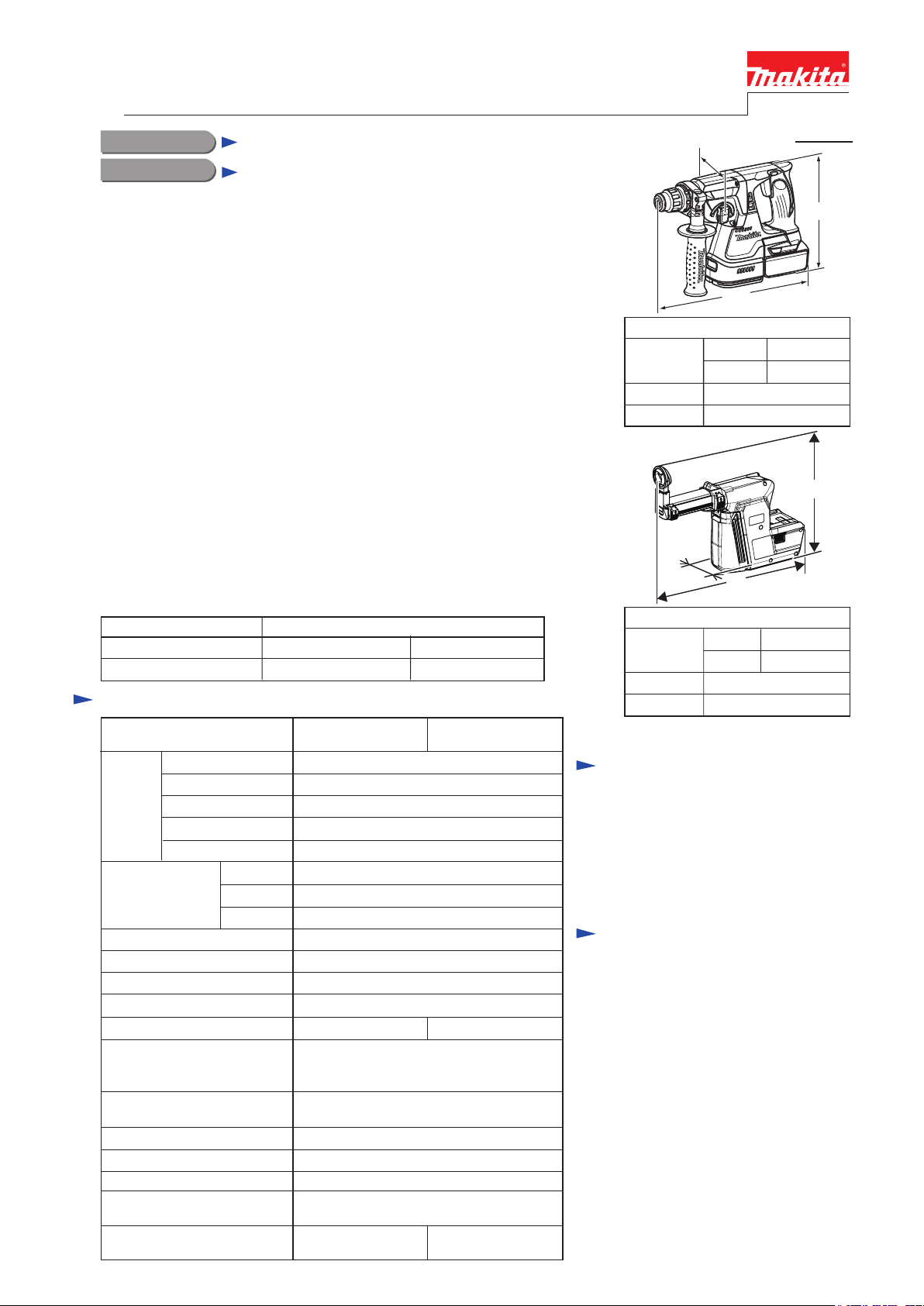
Cordless Combination Hammer 24mm (15/16")
*1 Model number for North and Central American countries.
CONCEPT AND MAIN APPLICATIONS
The subject models are 24mm (15/16") Cordless Combination Hammers
powered by 18V Li-ion Battery, featuring:
• Efficient Brushless DC motor provides higher productivity than that of
18V Cordless Combination Hammer model BHR202.
• Able to drill in concrete as fast or faster than 24V Cordless Combination
Hammer model BHR200.
• 3 operation modes (rotation only/ rotation with hammering/ hammering only)
• Quick change drill chuck for models BHR243 (LXRH02*
• Makita’s first Cordless Combination Hammers with Dust extraction system.
Note: • These products are not compatible with 1.3Ah battery BL1815.
DX01, DX02
These are the accessories as Makita’s first Dust extracting system exclusively
for model BHR242 (LXRH01*1), BHR243 (LXRH02*1).
This system is designed to collect dust effectively with on-off operation
of the tool’s on-off trigger switch interlocked with this system.
Note: • This system can be applied for concrete drilling only and comes with
Dust case, Filter and 5 pcs. of extra Sealing caps.
• The following parts are available optionally:
Dust case set, Filter set, Plastic carrying case (can be stored with BHR242
or BHR243)
For Model and its Chuck systemDust extraction system
DX01
BHR242 (LXRH01*1)
BHR243 (LXRH02*
1)
Quick change chuckDX02
Specification
Model
Voltage: V
Cell
Battery
Capacity: mm (")
No load speed: (min
Chuck capacity: mm (")
Bit shank
Quick change drill chuck No Yes
Operation mode
Variable speed control
by switch trigger
Reverse switch
Clutch (Torque limiter)
Weight of Dust
extracting system: kg (lbs)
Weight according to EPTA-
Procedure 01/2003: kg (lbs)
*2: for North and Central American countries only
Capacity: Ah
Energy capacity: W
Charging time: min.
Concrete
Steel
Wood
-1= rpm)
-1)
BHR242
(LXRH01*
22 with DC18RC (DC18RA*
(Rotation only/ Rotation with Hammering/
1)
18
Li-ion
3.0
54
24 (15/16)
13 (1/2)
27 (1-1/16)
0 - 950
0 - 4,700Blows per min.: (bpm=min
10 (3/8)
Adapted for SDS-PLUS
3 modes
Hammering only)
Yes
YesConstant speed control
Yes
Yes
1.3 (3.0) for DX01,
1.4 (3.0) for DX02
1) only
Normal chuck
BHR243
(LXRH02*1)
2)
3.4 (7.6)3.3 (7.2)
PRODUCT
P 1/ 25
W
H
L
Dimensions: mm (")
Length (L)
Width (W)
Height (H)
Length (L)
Width (W) 88 (3-1/2)
Height (H)
BHR242
BHR243
W
Dimensions: mm (")
DX01
DX02
328(12-7/8)
353(13-7/8)
85 (3-3/8)
213 (8-3/8)
H
L
372(14-5/8)
397(15-5/8)
287 (11-1/4)
Standard equipment
Side grip assembly ............................ 1
Depth gauge (Stopper pole) .............. 1
Plastic carrying case
Quick change drill chuck set
for BHR243 (LXRH02*1) only ....... 1
Note: The standard equipment for the tool
shown above may vary by country.
......................... 1
Optional accessories
SDS-PLUS bits, Taper shank T.C.T bits,
Taper shank adapter, Cotter, Center bit,
Core bit adapter, Drill chuck assembly,
Chuck adapter, Drill chuck S13,
Chuck key S13, Keyless drill chuck,
Tool holder set, Dust cup 5 & 9,
Dust cup set, Bull point, Cold chisel,
Grooving chisel, Scaling chisel,
Scraper assembly, Grease vessel 30g,
Blow out bulb, Safety goggles,
Bit grease, Plastic carrying case,
Battery BL1830,
Fast charger; DC18RA*2, DC18RC,
Charger; DC18SC, DC24SC,
Automotive charger DC18SE,
Dust extraction system (DX01, DX02)
Page 2

Repair
CAUTION: Repair the machine in accordance with “Instruction manual” or “Safety instructions”.
[1] NECESSARY REPAIRING TOOLS
DescriptionCode No. Use for
Retaining ring pliers ST-2N1R003 removing Ring spring 19 from Tool holder complete/ Tool holder guide complete
Retaining ring pliers ST-21R004
Drill chuck extractor1R139 removing Spiral bevel gear 32
Ring spring setting tool A1R164 assembling Oil seal 25 to Gear housing complete
T-type hex wrench 3-1271R170 removing M4 hex socket head bolts
Tip for Retaining ring pliers1R212 attachment of 1R003
1/4" hex shank bit for M41R228 removing M4 hex socket head bolts (if the bolt head damages.)
Pipe 301R232 assembling Oil seal 25 to Gear housing complete
Round bar for arbor 30-1001R252 removing Oil seal 25 from Gear housing complete
V block1R258 assembling Oil seal 25 to Gear housing complete
Bearing extractor1R269 removing Ball bearing 626DDW
Ring spring 26 setting tool B1R273 assembling Cup sleeve / Ball bearing 6806LLU to Gear housing complete
Round bar for arbor 7-501R281 removing Spiral bevel gear 32
1R356 removing Ball bearings from Rotor
1R369 removing / assembling Spiro lock washer 30
Bearing plate 10mm for
arbor press
Jig for Spiro lock washer for
spring type models
Ring spring extractor1R388 removing Ring spring 28
removing Retaining ring 21 for BHR243 from Armature shaft
assembling Ring 8Bearing setting plate 10.21R033
assembling Cam shaftBearing setting plate 15.21R035
removing / assembling Spiro lock washer 30Gear extractor (large)1R045
P 2/ 25
Page 3
Repair
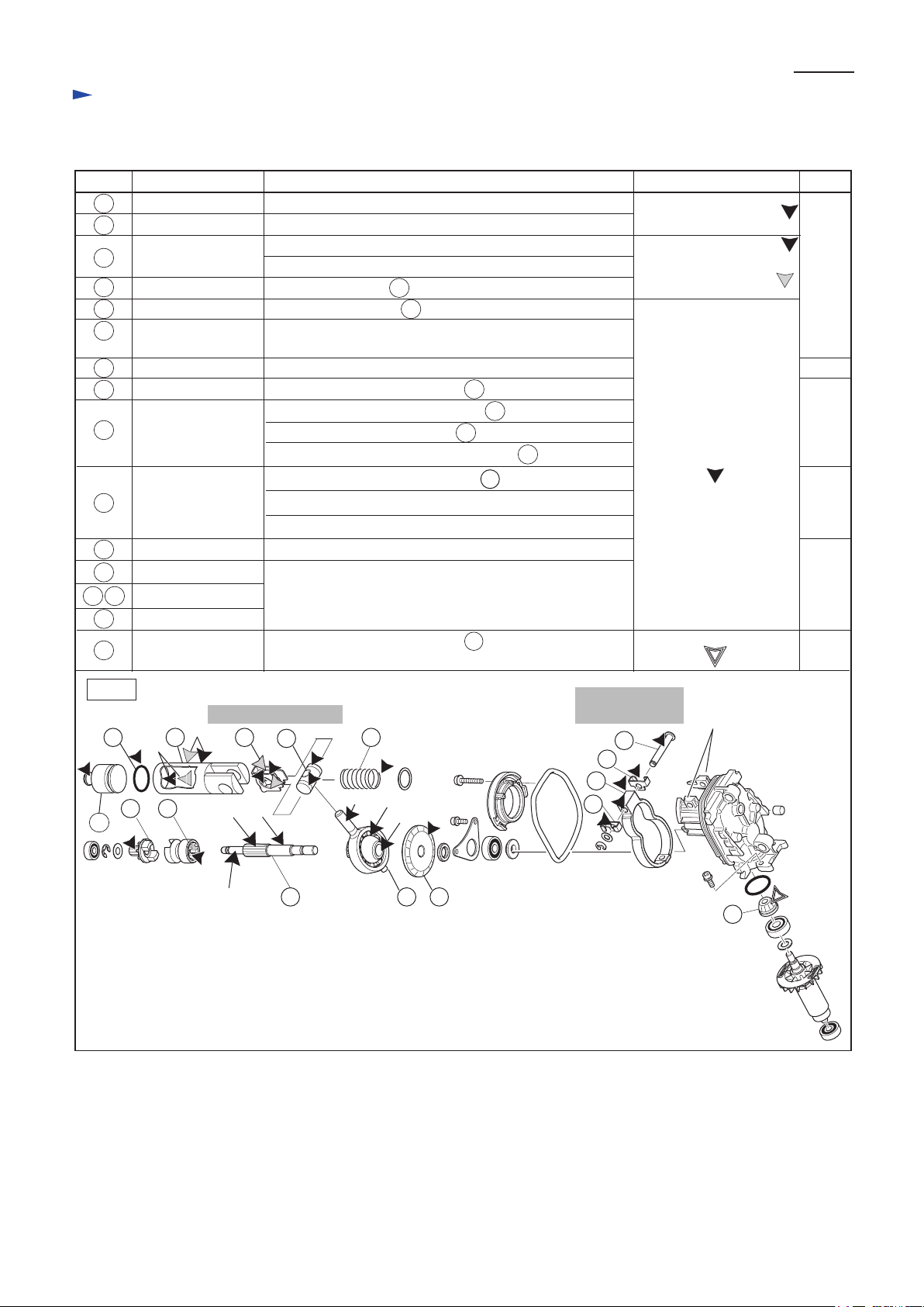
[2] LUBRICATION
Apply the following grease to protect parts and product from unusual abrasion.
Item No. Description Portion to lubricate Lubricant
Striker
46
O ring 17.5 Whole surface
47
48
Piston cylinder
49
Guide plate Inside that contacts 50 Piston joint
50
Piston joint Grooves that contact 49 Guide plate
51
Compression spring14End to be fixed to the boss in Inner housing complete
Spur gear 10 Gear portion that engages with Spur gear 51
56
57
Clutch cam A
58 Cam shaft
Swash bearing 10
59
Spiral bevel gear 32
60
73
Flat fillister HD pin 6
74 76
Weight holder guide
75 Counter weight
Spiral bevel gear 11
80
complete
Whole surface of projection
(a) Inside where Striker moves
(b) Outside that contacts Tool holder (guide) complete
(See Fig. 3.)
Gear portion that engages with 58 Cam shaft
(c) Gear portion that engages with 57 Clutch cam A
(d) Portion to be inserted into 59 Swash bearing 10
(e) Cylindrical portion to be inserted into 56 Spur gear 10
(f) Pole portion to be inserted into 50 Piston joint
(g) Ball bearing portion
(h) Inside of hole
Gear portion that engages with Armature shaft gear
Portion that contacts the hinge of Inner housing complete
Gear portion that engages with 60 Spiral bevel gear 32
[in the room of Inner housing complete for Spiral bevel gear 32]
Makita grease RB No.00
Makita grease RB No.00
and
Molybdenum disulfide
Makita grease RB No.00
Makita Grease FA No. 2
P 3/ 25
Amount
a little
3g
a little
See
Fig. 3.
a little
3g
Fig. 1
47 48
(a)
56
46
57
Transmission parts
(b)
49
(c) (d)
(e)
50 51
58
(f)
(g)
(h)
59
60
Counterweight
section
73
74
75
76
hinge of Inner
housing complete
80
Page 4
Repair
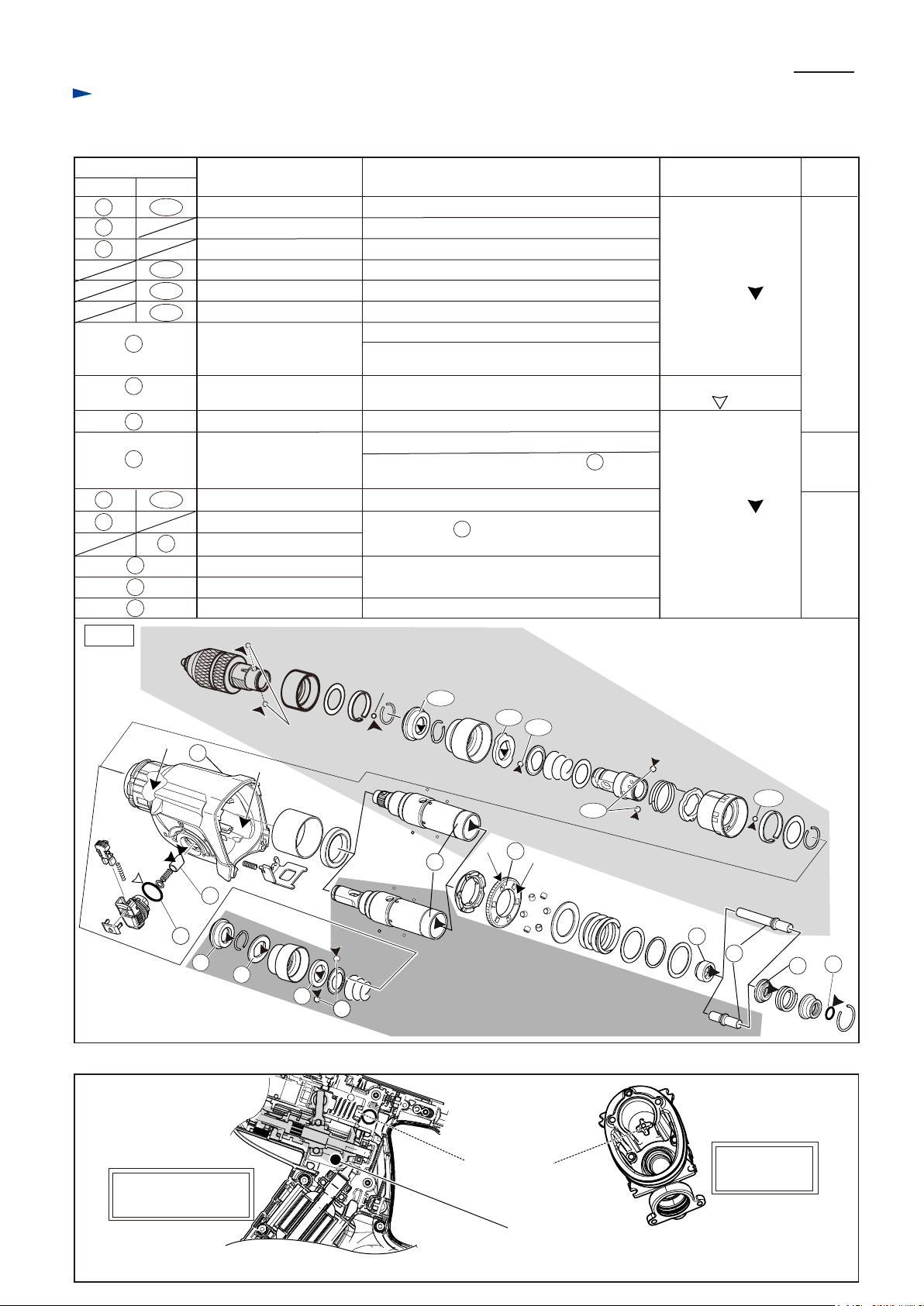
[2] LUBRICATION (cont.)
Apply the following grease/ oil to protect parts and product from unusual abrasion.
Item No.
BHR242 BHR243
1
105
6
8
108
114 Steel ball 6 Entire surface
118 Steel ball 5.0 Entire surface
15
22
32
28
109
30
30
39
Description Portion to lubricate Lubricant Amount
Cap 35
Lip portion where Bit is to be inserted
Rubber washer 16 Inner periphery
Ring 21 Inner periphery
Stopper Inner periphery
(a) Oil seal 25 in Gear housing complete
Gear housing complete
(b) Inside where Swash bearing section rotates
(See Fig. 3.)
O ring 21
Entire surface
Push corn25 Outer surface
(c) Gear portion
Spur gear 51
(d) Surface where Clutch portion of 30 Tool
holder (guide) complete contacts
Steel ball 7.0
Tool holder complete
Tool holderguide complete
Sleeve 9B
Washer 1041
O ring 944
Entire surface
Inside where 48 Piston cylinder reciprocates
Inside where Impact bolt A/ B reciprocates
Entire surface
P 4/ 25
Makita grease
RB No.00
a little
Makita lubricating oil
VG100
2g
Makita grease
RB No.00
a little
Fig. 2
Fig. 3
Quick change drill chuck: Apply Makita grease RB No. 00 to
two Steel balls 6 and one Steel ball 5.
(a)
22
15
Steel ball 5
Steel ball 6
(2 pcs.)
(b)
25
1
6
105
30
BHR242
(c)
108
109
32
8
28
(d)
BHR243
114
39
Impact bolt A
118
Impact bolt B
40
41
44
Cross section around
Swash bearing 10
boss for fixing
Compression
spring 14
Inside view of
Inner housing
Put 16g Makita grease RB No 00 by using the space
(designated by the black dot) to lubricate
Swash bearing section and Cam shaft section.
Page 5
Repair
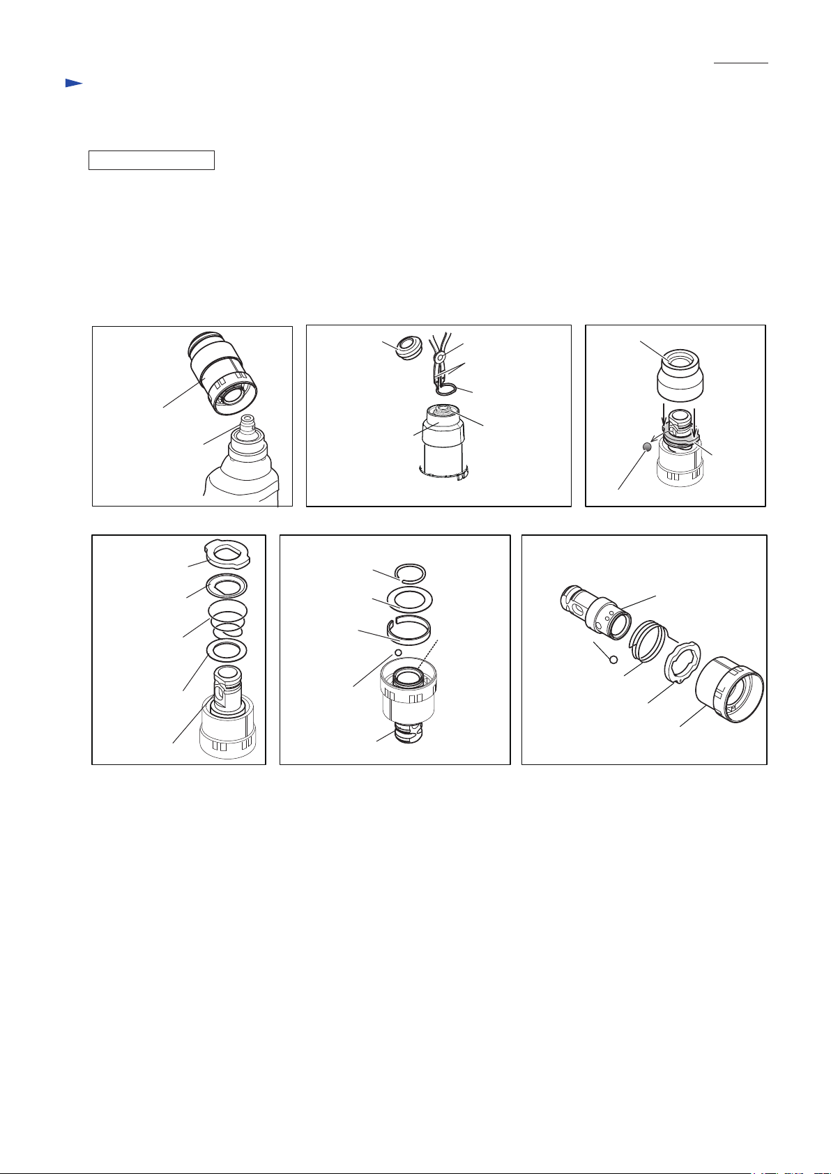
[3] DISASSEMBLY/ASSEMBLY
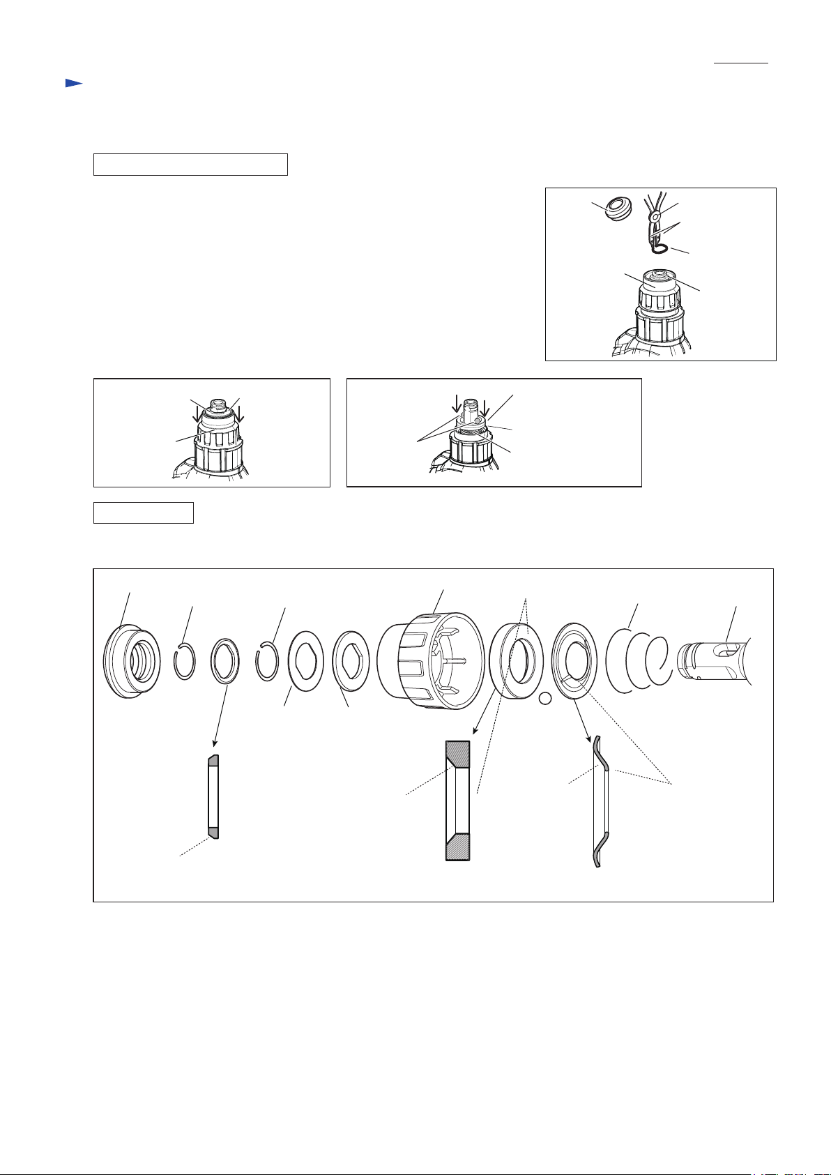
[3] -1A. Bit holder section for BHR242
DISASSEMBLING for BHR242
Fig. 4
(1) Remove Cap 35.
(2) Separate Ring spring 14 from the groove of Tool holder complete using
1R003 with 1R212. (Fig. 4)
Washer 16 on Ring spring 15 is removed.
(3) Remove Ring spring 15 in the same way while pressing down Chuck cover.
(Fig. 5) Then pick up Flat washer 17 and Rubber washer 16
from the space between Chuck cover and Tool holder complete.
Chuck cover is removed.
(4) Remove two Steel balls 7.0 while pressing down Ring 21. (Fig. 6)
Ring 21, Guide washer and Conical compression spring 21-29 are removed.
Cap 35
Chuck cover
P 5/ 25
1R003
1R212
Ring spring 14
(black)
Groove of
Tool holder
complete
Fig. 5
Ring spring 15
(silver)
Chuck cover
ASSEMBLING
Assemble by reversing the disassembly procedure. Refer to Fig. 7 for the directions of the components.
Fig. 7
Ring spring 14
(black)
Flat washer 17
Ring spring 15
(silver)
Flat washer 17 Rubber
Fig. 6
Steel ball 7.0
(2 pcs.)
washer 16
Ring 21
Guide washer
Conical compression
spring 21-29
Chuck coverCap 35
flat side
Steel ball
7.0 (2 pcs.)
Conical compression
spring 21-29
Tool holder
complete
chamfered
portion
chamfered
portion
Ring 21
concave
side
Guide washerWasher 16
convex
side
Page 6
P 6/ 25
Repair
[3] DISASSEMBLY/ASSEMBLY
[3] -1B. Holder section for BHR243
DISASSEMBLING
(1) Remove Tool holder set from Tool holder guide complete. (Fig. 8)
(2) Remove Cap 35, then separate Ring spring 19 from the groove of Tool holder using 1R003 with 1R212. (Fig. 9)
(3) Remove Chuck cover, then remove Steel ball 7.0 while pressing down Stopper. (Fig. 10)
Stopper, Guide washer, Conical compression spring 21-29 and Flat washer 21 are removed. (Fig. 11)
(4) Remove Ring spring 21 with 1R004 from Tool holder guide complete side.
Flat washer 24, Leaf spring and Steel ball 5 are removed. (Fig. 12)
(5) Remove two Steel balls 6, Torsion spring 31 and Change ring from Tool holder. (Fig. 13)
Fig. 8
Tool holder set
Tool holder guide
complete
Fig. 11 Fig. 13Fig. 12
Stopper
Guide washer
Conical
compression
spring 21-29
Flat washer 21
Fig. 9 Fig. 10
Ring spring 21
Flat washer 24
Leaf spring
Steel ball 5
Cap 35
Chuck cover
Tool holder set
1R003
1R212
Ring spring 19
Groove of
Tool holder
Tool holder
guide
complete
side
Chuck cover
Stopper
Steel ball 7.0
Tool holder
Steel ball 6
(2 pcs.)
Torsion spring 31
Change ring
Tool holder
Tool holder
Change cover
Page 7
Repair
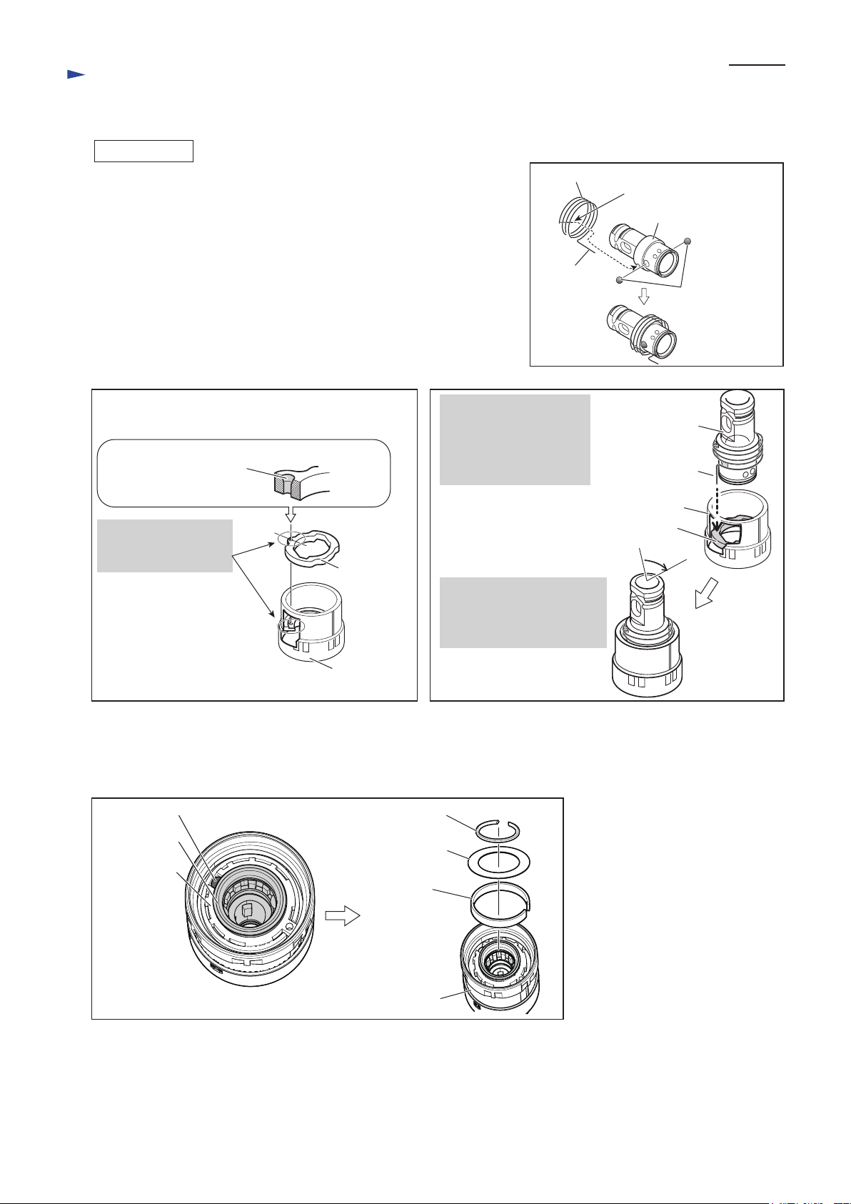
[3] DISASSEMBLY/ASSEMBLY
[3]-1B. Holder section for BHR243 (cont.)
P 7/ 25
ASSEMBLING
(1) Assemble Torsion spring 31 to Tool holder as follows:
• Set two Steel balls 6 on the holes of Tool holder.
• Insert the short arm of Torsion spring 31 into the hole of Tool holder.
Note: Apply Makita grease No. RB No. 00 to two Steel balls 6 to prevent
them from falling. (Fig. 14)
(2) Assemble Change ring to Change cover. (Fig. 15)
(3) Assemble Tool holder to Change cover. (Fig. 16)
Fig. 15 Fig. 16
Insert the long arm of
Torsion spring 31 into
Note:
Face the chamfered end
of the hole upward.
Align the hole of
Change ring with
that of Change cover.
[Section a - a']
a
a'
Change ring
the hole of Change cover
through the hole of
Change ring.
By turning Tool holder
approx. 75
Tool holder can be fastened
to Change cover.
Fig. 14
Torsion spring 31
long arm
°
clockwise,
short arm
Tool holder
Steel ball 6 (2pcs.)
Tool holder
long arm of
Torsion spring 31
Change cover
Change ring
75
°
Change cover
(4) Put Steel ball 5.0 in the groove surrounded by Change cover and Tool holder. (left in Fig. 17)
(5) Set Leaf spring and Flat washer 24 in change cover, then secure them with Ring spring 21. (right in Fig. 17)
(6) As for Cap 35 side, assemble the components by reversing disassembly procedure. Refer to the previous page.
Fig. 17
Steel ball 5.0
Change cover
Tool holder
Ring spring 21
Flat washer 24
Leaf spring
Change cover
Page 8
Repair
[3] DISASSEMBLY/ASSEMBLY
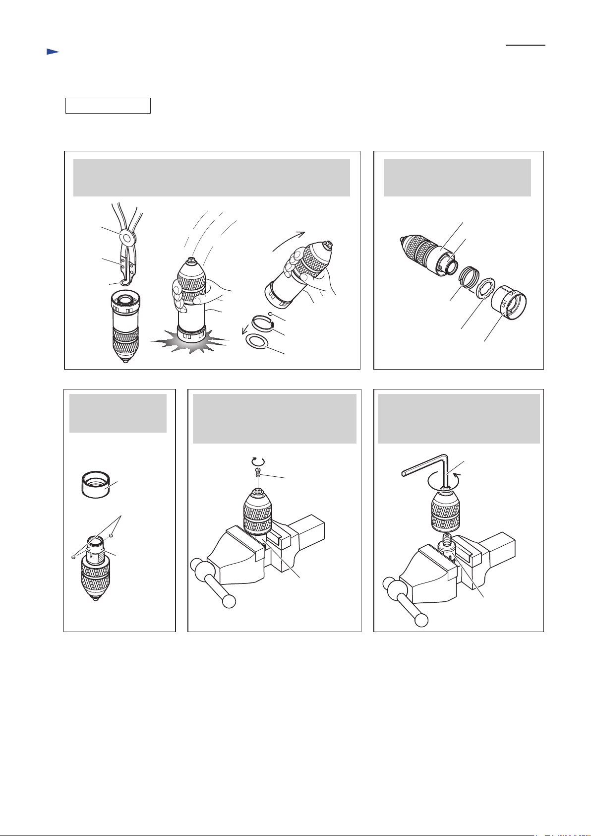
[3]-2. Drill chuck assembly for BHR243
DISASSEMBLING
Drill chuck assembly can be disassembled as drawn in Figs. 18 to 22.
Fig. 18 Fig. 19
P 8/ 25
After Removing Ring spring 21, strike Drill chuck assembly against
workbench which is covered with a cloth as a cushion.
Flat washer 24, Leaf spring and Steel ball 5.0 can be removed.
1R003
1R212
Ring
spring 21
Steel ball 5.0
Leaf spring
Flat washer 24
Remove Spacer and
two Steel balls 6 from
Chuck holder.
Clamp the flats of Chuck holder in vise,
then unscrew M6x22 Flat head screw
by turning it clockwise using Impact
driver.
Pull off Change cover.
Change ring and Torsion spring 31
can be removed.
Spacer
Chuck holder
Torsion spring 31
Change ring
Change cover
Fig. 22Fig. 21Fig. 20
Clamp the flats of Chuck holder in vise,
then separate Drill chuck from Chuck
holder by turning it counterclockwise
using Hex wrench 10.
Spacer
Steel ball 6 (2 pcs.)
Chuck holder
Hex wrench 10
M6x22
Flat head screw
Chuck holder
Chuck holder
Page 9

P 9/ 25
Repair
[3] DISASSEMBLY/ ASSEMBLY
[3] -2. Drill chuck assembly for BHR243 (cont.)
ASSEMBLING
(1) Holding the flat portions of Chuck holder in vise, assemble Drill chuck to Chuck holder by turning it clockwise
using Hex wrench 10.
(2) Secure Drill chuck with M6x22 Flat head screw by turning it counterclockwise using Impact driver.
(3) Assemble Drill chuck to Spacer. (Fig. 23) Then mount two Steel balls 6. (Fig. 24)
(4) Mount Torsion spring 31. Then assemble Drill chuck to Change cover. (Fig. 25)
(5) Mount Steel ball 5, Leaf spring and Flat washer 24 to Chuck holder, then secure them with Ring spring 21. (Fig. 26)
Fig. 23 Fig. 24
Steel ball 6 (2 pcs.)
While fitting the flat portions
of Chuck holder to Spacer,
mount Drill chuck to Spacer.
Spacer
Fig. 25
Insert the short arm of Torsion
spring 31 into the hole of
Chuck holder using small pliers.
hole for
Torsion spring 31
Spacer
Chuck holder
short arm of
Torsion spring 31
Chuck holder
Chuck holder
Insert the long arm of Torsion spring 31
into the hole of Change cover through
the hole of Change ring, then assemble
Change ring to Change cover. (See Fig. 6.)
Torsion spring 31
long arm of
Torsion spring 31
Change ring
Change cover
Spacer
Note: Apply Makita grease RB No.00 to Steel balls 6
to protect them from falling.
By turning Drill chuck
approx. 75
Drill chuck can be fastened
to Change cover.
Drill
chuck
Change
cover
°
clockwise,
75
°
Fig. 26
Leaf spring
Flat washer 24
Ring spring 21
Steel ball 5
Page 10

P 10/ 25
Repair
[3] DISASSEMBLY/ASSEMBLY
[3]-3. Change lever
DISASSEMBLING
(1) Remove dust and dirt from Change lever and the grooved area on Motor housing.
(2) Set Change lever to Hammer mode. (Fig. 27)
Note: If it is hard to set Change lever to Hammer mode because of getting stuck in the halfway,
turn the bit holder section / holder section of the machine by hand and then try again.
(3) While pushing Lock button into Change lever, turn Change lever to the right fully over the position of Hammer mode.
(Fig. 28)
(4) Pull out Change lever from the position drawn in Fig. 29. If it is impossible to remove Change lever by hand, lever it up
with slotted screwdriver.
Note: Be careful not to remove Change lever without placing as drawn in Fig. 29.
The exact positioning prevents Change lever from breakage.
(5) Disassemble Change lever section as drawn in Fig. 2.
Fig. 27
Hammer mode
Fig. 28 Fig. 29
Change lever Lock button
ASSEMBLING
(1) Assemble the following parts to Change lever.
▪ Lock button ▪ Compression spring 3 ▪ Change lever cover ▪ O ring 21 (Apply Makita lubricating oil VG100.)
▪ Thin washer 16 ▪ Compression spring 5 ▪ Push corn
(2) Apply Makita grease RB No. 00 to Push corn.
(3) Fit the top of Push corn into the groove of Clutch cam A, and insert the hinge of Change lever into the hole of
Motor housing while keeping the exact position drawn in Fig. 29. (Refer to Fig. 30.)
(4) While pushing Lock button, turn Change lever to the left.
Note: Make sure that Change lever works properly by setting it to Drill mode/ Rotary hammer mode/ Hammer mode.
If it is hard to set Change lever to each mode because of getting stuck in the halfway; try 1 or 2 as follows:
1. Turn the bit holder section / holder section of the machine by hand and then try again.
2. Install battery and pull Switch very slightly a second to run the machine.
Fig. 30
Change lever section
Page 11

P 11/ 25
Repair
[3] DISASSEMBLY/ASSEMBLY
[3]-4. Rotor
DISASSEMBLING
(1) Loosen four 4x35 Tapping screws, and then remove Battery housing R and Housing R in order from their housings L.
(Fig. 31)
(2) Remove Gear housing section as drawn in Fig. 32.
Inner housing in Gear housing section comes with Rotor.
(3) Loosen two M4x12 Hex socket head bolts with 1R170, and then remove Bearing retainer A. (Fig. 33)
(4) Pull Rotor section out straight from Inner housing by hand.
Note: Due to the effect of O ring 22.4 in the groove in Bearing room, pulling is preferable to tapping for removing Rotor
section.
(5) Insert a set of 1R356 under Ball bearing 608LLU, and press the shaft of Rotor in the center of Spiral bevel gear 11
complete with 1R281. (Fig. 34)
Ball bearing 608LLU, Flat washer 8 and Spiral bevel gear 11 complete are removed.
Remove 626DDW from Rotor with 1R269.
Fig. 31
Housing R
Gear housing section
Fig. 32
Two holes of Inner housing
for inserting two bosses of
Housing L
Battery
housing R
4x18 Tapping
screw (10 pcs.)
Fig. 33
1R170
Bearing retainer A
M4x12 Hex
socket head bolt
4x35 Tapping
screw (4 pcs.)
Rotor section
Fig. 34
Arbor press
1R281
1R356
Spiral bevel gear
11 complete
Rotor section
Stator
Ball bearing 608LLU
on Flat washer 8
Shaft of Rotor
Ball bearing 626DDW
ASSEMBLING
Assemble by reversing the disassembly procedure.
Note: Be sure to set Flat washer 8 in place between Fan and Ball bearing 608LLU.
Page 12

Repair
[3] DISASSEMBLY/ASSEMBLY
[3]-5. Torsion spring 6 for Connector, Battery housing
ASSEMBLING
See Fig. 35.
Set Torsion spring 6 into Housing L, and then assemble Connector to Compression spring 6. Refer to A .
Set Opener in place. Refer to B .
When Battery housing L and R are matched, do not fail to assemble the parts shown in C .
Fig. 35
A
Hold one end of Torsion spring 6
with the inner wall of Housing L.
Insert the hinge of Connector
into the coil of Torsion spring 6.
P 12/ 25
Hook the opposite end
of Torsion spring with
the step of Housing L.
C
B
Align the chamfered side
of Opener with the walls
of Housing L.
(Housing set)
Opener
Cushion
rubber (R)
Rubber pin 5
Pin 1.5
Battery housing set
Cushion rubber (L)
(behind Terminal)
Cushion
Page 13

P 13/ 25
Repair
[3] DISASSEMBLY/ASSEMBLY
[3]-6. Torque limiter section
DISASSEMBLING
(1) Disassemble Tool holder section. (Figs. 4 to 6 for BHR242/ Figs. 8 to 13 for BHR243.)
(2) Disassemble Change lever. (Figs. 27 to 29)
(3) Remove Gear housing section from Motor housing, and then remove Rotor section from Gear housing section.
(Figs. 31 to 33)
(4) While holding Gear housing section by hand, tap the top of Tool holder (guide) complete with plastic hammer. (Fig. 36)
Note: 1. Grease falls from Gear housing section. Receive the grease with cloths.
2. Do not lose Flat washer 30 between
(5) Remove Stop ring EXT U-6 from Cam shaft. (Fig. 37)
The ring tends to be caught by Spur gear 51, and therefore, it interferes in the disassembling step.
(6) Remove Tool holder section. (Fig. 37)
(7) Set 1R045 and 1R369 to Tool holder section. (Fig. 38)
(8) Compress Compression spring 31 of Tool holder section by turning the handle of 1R045 clockwise. (Fig. 39)
(9) Remove Spiro lock washer 30 from Tool holder (guide) complete by gradually sliding it on Tool holder (guide) complete
with Thin-slotted screwdriver. (Fig. 40) Tool holder (guide) section are disassembled as drawn in Fig. 41.
Tool holder section
and Inner housing.
Fig. 36
Tool
holder
section
Fig. 39 Fig. 40
Spiro lock washer 30
1R045
1R369
(Compression
spring 31)
Fig. 37 Fig. 38
Super gear 51
Stop ring
EXT U-6
Flat washer 7
Swash bearing section
Magnified view of Fig. 39
Thin-slotted
screwdriver
Tool holder section Tool holder section
1R369
Tool holder (guide) complete
1R045
Ends of Spiro lock
washer 30
1R369
1R045
Fig. 41
Pin 6 (6 pcs.)Driving flangeTool holder (guide)
complete
Spur gear 51Steel ball 3 (4 pcs.)
ASSEMBLING
Assemble by reversing the disassembly procedure.
Note: 1. Set Spiro lock washer 30 in place with 1R369 and 1R045.
2. After assembling the components of Tool holder section, set Flat washer 7 and Stop ring EXT U-6 to Cam shaft.
(Refer to Fig. 37)
Flat washer 30
(thick shape)
Flat washer 30
(thin shape 2 pcs.)
Spiro lock washer 30Compression spring 31
Page 14

P 14/ 25
Repair
[3] DISASSEMBLY/ASSEMBLY
[3]-6. Impact bolt in Torque limiter section
DISASSEMBLING
(1) Put 1R388 into Tool holder (guide) complete, then push 1R388 in vise with the access holes on Tool holder (guide)
complete parallel to Vise. (Fig. 42)
O-ring case B is moved toward the top of Tool holder (guide) complete, and therefore, Ring spring 28 can be relieved
from O-ring case B.
(2) When the end gap of Ring spring 28 is in the access hole, slide it with slotted screwdriver until it is completely hidden.
(3) Using slotted screwdriver, tap Ring spring 28 through the two access holes alternately to push it out of the inner groove
of Tool holder (guide) complete.
Note: As soon as a part of Ring spring 28 is removed from the inner groove of Tool holder (guide) complete, insert another
slotted screwdriver in between Ring spring 28 and the inner groove of Tool holder (guide) complete to prevent
returning the removed portion back to the inner groove.
(4) The components are removed by tapping with Phillips screwdriver and Plastic hammer from bit installation side of
Tool holder (guide) complete. (Fig. 43)
Fig. 42
The directions of two access holes on Tool holder (guide) complete
have to be parallel to Vise.
Vise Vise
1R388
1R388 O-ring case B
holes on both side of Tool holder (guide)
complete to access inside
Fig. 43
°
90
slotted
screwdriver
Ring spring 28
inner groove of Tool holder (guide) complete
Bit installation side
BHR242: Impact bolt A
Sleeve 9B
BHR243: Impact bolt B
O ring 9O ring case B
Washer 10
Compression spring 20
Ring spring 28
Inner housing
side
Page 15

P 15/ 25
Repair
[3] DISASSEMBLY/ASSEMBLY
[3]-6. Impact bolt in Torque limiter section (cont.)
ASSEMBLING
(1) Assemble Impact bolt section to Tool holder (guide) complete as drawn in Fig. 44A/ 44B.
Fig. 44A
Impact bolt section in Tool holder complete for BHR242
Tool holder complete (140265-3)
Bit installation side Inner housing side
Sleeve 9B
Impact bolt A
Washer 10 Compression
spring 20
O ring case B with
O ring 9 fit inside
Note: These components
are directional.
Fig. 44B
Impact bolt section in Tool holder guide complete for BHR243
Tool holder guide complete (140266-1)
Bit installation
side
Note: These components
are directional.
(2) Push Ring spring 28 into the inner groove of Tool holder (guide) complete as drawn in Fig. 45.
Note: Do not reuse the removed Ring spring 28 if it is deformed or damaged.
Fig. 45
Note: 1. Use an extra Piston cylinder as a jig. Never use Piston cylinder that is
to be assembled to the machine.
Piston cylinder
as a jig
2. The end gap of Ring spring 28 must not be placed at the two holes of
Tool holder (guide) complete.
ø9mm
[cross-sectional view]
Sleeve 9B Washer 10 Compression
Impact bolt B
long short
[cross-sectional view]
ø9.5mm
spring 20
O ring case B with
O ring 9 fit inside
Inner housing side
end gap
Ring spring 28
Tool holder (guide)
complete
hole
Note: 2
Tool holder Guide)
complete
Ring spring 28
end gap
Note: 1
hole
Inner groove of
Tool holder (guide)
complete
[Correct] [Wrong]
Piston cylinder as a jig
Ring spring 28
O ring case B
Page 16

P 16/ 25
Repair
[3] DISASSEMBLY/ASSEMBLY
[3]-7. Swash bearing section, Piston cylinder section
DISASSEMBLING
(1) Disassemble Motor housing section, Gear housing section and Inner housing section.
(2) Remove Flat fillister HD pin 6, two Weight holder guides, Flat washer 6, Stop ring E-5, Inner support complete and
two M4x25 Hex socket head bolts from Inner housing. (Fig. 47)
(3) While pushing Piston cylinder, remove Counter weight from Swash bearing section as drawn in Fig. 48.
(4) Remove two M4x12 Hex socket head bolts with 1R170 or 1R228. (Fig. 49)
- Then pull Swash bearing section and Piston cylinder section out of Inner housing. (Fig. 49)
- Swash bearing section can be removed from Piston cylinder section with Inner housing attached as drawn in Fig. 50.
(5) Remove Ball bearing 606ZZ from Gear housing complete using the removed Swash bearing section. (Fig. 51)
Fig. 47
Flat fillister HD pin 6
M4x25 Hex socket
head bolt (2 pcs.)
Inner support complete
Fig. 49
M4x12 Hex socket head bolt (2 pcs.)
Note: These are thread locking screws.
Do not reuse them without applying
ThreeBond 1321B/ 1342 or
Loctite 242.
Weight holder guide
(2 pcs.)
Fig. 48
Flat washer 6
Stop ring E-5
Inner housing
Piston cylinder section
Swash bearing section
Piston cylinder
Counter
weight
Swash bearing
section
Fig. 50
Inner housing
Piston
cylinder
Push Piston cylinder into Inner housing
to tilt Swash bearing 10.
Fig. 51
Insert the shaft of Swash bearing section to the hole
of Ball bearing 606ZZ, and tilt it back and forth.
Ball bearing 606ZZ
in Gear housing complete
Swash bearing 10
Pull Swash bearing section horizontally
with Swash bearing 10 kept tilted, and
remove the pole of Swash bearing 10
toward the tilted direction.
Swash bearing section
Tap Gear housing complete with plastic hammer.
Ball bearing 606ZZ is removed together with
Swash bearing section.
Ball bearing 606ZZ
Page 17

P 17/ 25
Repair
[3] DISASSEMBLY/ASSEMBLY
[3]-7. Swash bearing section (cont.)
DISASSEMBLING
(6) Remove Stop ring EXT U-6 from Can shaft, then separate Flat washer 7, Spur gear 10 and Clutch cam A from Can shaft.
(7) Receive Spiral bevel gear 32 on 1R139 put on U-groove of Arbor press table and press out Cam shaft with 1R281
(ø7mm round bar) as drawn in Fig. 52.
The swash bearing section can be removed as drawn in Fig. 53.
Fig. 52
Arbor press
1R281
1R139
Spiral bevel gear 32
Arbor press table
Fig. 53
Flat washer 7 Bearing retainer BSpur gear 10
Stop ring
EXT U-6
ASSEMBLING
Assemble the Swash bearing section carefully to the directions of each part and the order shown in Fig. 53.
(1) Pass Cam shaft through Clutch cam A, and then receive Clutch cam A on 1R035.
(2) Pass Cam shaft through Swash bearing 10 and press-fit Spiral bevel gear 32 to Cam shaft until Spiral bevel gear stops.
(3) Pass Cam shaft through Ring 8 and Bearing retainer B, and then press-fit Ball bearing 608ZZ and Ring 8 to Cam shaft
with 1R033 carefully. Do not pinch Bearing retainer B by Ball bearing 608ZZ and Spiral bevel gear 32.
Note: When 1mm height of Cam shaft is projected out over Ring 8, the assembling work is successful. (Fig. 54) Check
the height at this time.
(4) Set Spur gear 10 and Flat washer 7 in place on Cam shaft, and secure them with Stop ring EXT U-6.
Fig. 54
Clutch cam A Swash bearing 10 Spiral bevel gear 32
Cam shaft Ring 8
(Flat shape)
Arbor press
1R033
Ball bearing 608ZZ
Ring 8
(stepped)
Clutch cam A
Cam shaft
1mm height
Top of Ring 8
Bearing retainer B Spiral bevel gear 32
1R035
Page 18

P 18/ 25
Repair
[3] DISASSEMBLY/ASSEMBLY
[3]-7. Swash bearing section, Piston cylinder section (cont.)
ASSEMBLING
(5) Set Compression spring 14 and Flat washer 14 to the projection of Inner housing as drawn in Fig. 55.
Insert Guide plate and Piston joint into Piston cylinder, and then pass the pole of Swash bearing 10 through Piston joint.
(Fig. 56)
(6) Assemble Inner support complete to Inner housing with two M4x25 Hex socket head bolts. (Refer to Fig. 47)
(7) Make sure that the gear teeth of Clutch cam A engage those of Swash bearing 10. (Fig. 57)
(8) Assemble Compression spring 4 and Lock plate to Gear housing. (Fig. 58)
Note: Apply Makita grease RB No. 00 to the end of Compression spring 4 on Lock plate mating side in order to do
the next step smoothly.
(9) While holding Lock plate by a finger so as not to drop from the guides of Gear housing, assemble Gear housing to
Inner housing. (Figs. 58 and 59)
Fig. 55
Fig. 56
Fig. 57
Compression spring 14
Flat washer 14
Projection of
Inner housing
Guide plate Inner housingPiston cylinder
It is not necessary
to position this hole.
Pole of
Swash bearing 10
Fig. 58
Gear housing complete Compression spring 4 Lock plate
Piston joint
Note: Apply Makita grease RB No. 00
to the specific portions of Piston joint
designated by .
Clutch cam A
Correct assembling
Fig. 59
Swash bearing 10
Guides of Gear housing
Apply Makita grease RB No. 00 to the portion
of Compression spring 4 designated by .
Page 19

P 19/ 25
Repair
[3] DISASSEMBLY/ASSEMBLY
[3]-8. Oil seal 25, Cup sleeve, Ball bearing 6806LLU
DISASSEMBLING
(1) Assemble Inner housing complete to Gear housing complete.
(2) Put Inner housing complete on U-groove table portion of arbor press, then press Oil seal 25, Cup sleeve and Ball
bearing 6806LLU out of Gear housing complete using 1R252.
ASSEMBLING
(1) Press-fit Ball bearing 6806LLU into Cup sleeve. (Fig. 60)
(2) While receiving the stepped collar of Gear housing complete on 1R258 as drawn in Fig. 61,
press-fit Oil seal 25 with 1R232 until it stops. (Fig. 62)
Oil seal 25 is not yet inserted completely because the outer diameter of 1R232 is larger than
that of Oil seal setting hole.
(3) Press-fit Oil seal 25 to the original position with 1R164 until it stops. (Fig. 63)
(4) Press-fit Cup sleeve with Ball bearing 6806LLU into the place using 1R273. (Fig. 64)
Note: Too much pressure will deform Oil seal 25 and Cup sleeve. Press-fit them with gentle
pressure.
Fig. 61 Fig. 62
Gear housing
complete
the stepped collar
(gray color portion)
to be put on 1R258
Oil seal 25
Fig. 60
Ball bearing
6806LLU
Cup sleeve
1R232
36mm
1R258
Fig. 63 Fig. 64
30mm
1R164
34mm
Oil seal 25
1R273
37mm
37mm
100mm
Cup sleeve with Ball bearing 6806LLU
at the bottom
Note: Be careful to the direction.
1R258
Page 20

Repair
[3] DISASSEMBLY/ASSEMBLY
[3]-9. Motor of Dust extraction system DX01, DX02
Note: Special repairing tool and Lubricant are not required.
DISASSEMBLING
(1) Separate Housing R and eight 4x18 Tapping screws from Housing L.
(2) Remove Baffle plate, Filter plate, Sponge sheet C and Motor complete as an assembled part. (Fig. 65)
Fig. 65
P 20/ 25
Motor complete
Note: Replacing Fan separately is not allowed.
ASSEMBLING
Assemble the components by reversing the disassembly procedure.
Guide plate, Cushion and four Rubber pins 4 are on not only Housing R but also Housing L, and therefore, be careful not
to drop their parts.
Fig. 66
Guide plate
Baffle plate
Sponge sheet C
Baffle plate
Cushion
Rubber pin 4 (4 pcs. on this side)
Rack B
Earth rubber
Page 21

P 21/ 25
Repair
[3] DISASSEMBLY/ASSEMBLY
[3]-10. Slide levers of Dust extraction system DX01, DX02
DISASSEMBLING
• Slide lever B on Housing L
Remove Rack B and Compression spring 3 in Housing L as drawn in Fig. 67, and then move Slide lever B toward
the upper direction like the arrow mark. (Fig. 67)
Fig. 67
Inside of Housing L
Housing L
Slide lever B
Compression spring 3
Rack B
Outside of Housing L
(viewed from the opposite)
Slotted screwdriver
Housing L
Arrow mark
on Slide lever B
• Slide lever A on Slide pipe
Remove Collector base A (DX01)/ B (DX02) from Slide pipe by releasing the hooks with a thin-slotted screwdriver,
and then separate Rack A, Compression spring 3, Stopper base and Slide lever A. (Fig. 68)
Fig. 68
Collector
base A/ B
1
3
Hooks to set in the holes
on sides of Slide pipe
Slide pipe
Stopper base
2
Slide lever A
Rack ACompression spring 3
Note: Remove Rack A, Compression spring 3 and Slide lever A
in the same way as mentioned in Fig. 67.
Page 22

P 22/ 25
Repair
[3] DISASSEMBLY/ASSEMBLY
[3]-11. Tips on repair of Dust extraction system DX01, DX02
DISASSEMBLING
• Hose 30 is not glued on the other parts, and therefore it is possible to remove Hose 30 from Collector base A (DX01)/
B (DX02) and Inner pipe. (Fig. 69)
When it is difficult to remove because of the tight contact, peel it with a thin-slotted screwdriver. (Fig. 69)
Fig. 69
Hose 30
Collector base A/ B
ASSEMBLING
• Hose 30 is not glued on the other parts, and therefore it is possible to remove Hose 30 from Collector base A (DX01)/
B (DX02) and Inner pipe. (Fig. 69)
When it is difficult to remove because of the tight contact, peel it with a thin-slotted screwdriver. (Fig. 69)
• When reassembling Collector base A/B and Inner pipe, keep a right angle between them.
In assembly of housing L to R and shrinkage of Hose 30, while turning the hose 30 counterclockwise, snap the hooks of
Collector base A/ B into the holes of Slide pipe as drawn in Fig. 70. (Reverse the step shown in Fig. 68.)
• While turning Hose 30 clockwise, adjust your desired positions of Hose, Collector base A/ B and Inner pipe each other.
The inner diameter of the spring of Hose is expanded, and consequently this way allows loose contact of Hose during
revolving.
Fig. 70
Page 23

Circuit diagram
Fig. D-1
Color index of lead wire’s sheath
Black Orange
White
Red Yellow
Blue
Brown
P 23/ 25
BHR242,
BHR243
Switch
Stator
Connector to Dust
extraction system
(DX01, DX02)
Orange mark
White mark
Fig. D-2
DX01,
DX02
Terminal
Controller
Black mark
Connector
to BHR242
and BHR243
Two hole type
Line filter (if used)
One hole type
Line filter ø10-30mm (if used)
Controller
DC motor
Red mark
Page 24

Wiring diagram
Fig. D-3
P 24/ 25
BHR242, BHR243
Connect Lead wires to Controller/ Terminal
with Flag receptacles as drawn below.
Flag receptacles
Black
lead wire
White
lead wire
Stator
Terminal
Rib A
Do not put any lead
wires on this boss.
Flag receptaclesController
Set Controller in place with Flag receptacles faced
as drawn above.
Rib B
Orange
lead wire
Connector
Black
lead wire
Red
lead wire
Controller
Slacks of Lead wires between Controller and
Connector/ Stator have to be placed over the line
extended from Rib D.
Rib D
Line extended from Rib D
Rib C
Lead wires to Connector and Stator lead wires
have to be routed between Rib A and Rib B.
Do not put Stator lead wires on Rib C.
Lead wires to Connector have to be routed
between Rib B and Rib D.
Terminal
Route the lead wires between Connector and Controller to the bottom of Housing L
so as not to rise on the top line of Rib C. Turn them back to set Connector in place.
Place the turned portion over the line extended from Rib D.
Line extended from Rib D
The bottom of Housing L
viewed from the upper side
Controller
Turned portion
Rib D
Rib C
Connector
Page 25

Wiring diagram (cont.)
Fig. D-4
Connector
P 25/ 25
DX01, DX02
Connector viewed from lead wire installation side
Connect Lead wires to Connector with
Flag receptacles as drawn below.
Connector
Black lead wire
Lead wires between Connector and Controller have to fixed
with these lead wire holders. Do not slack them between
the lead wire holders.
Put Lead wires between Connector and Controller into this groove.Put Lead wires between Connector and Controller into this groove.
Connect Lead wires to DC motor with
Flag receptacles as drawn below.
Red lead wire
White lead wire
Pass Lead wires through the holes of
Line filter one by one and place them
in the space between Ribs.
(Line filter is not used for some countries.)
DC motor
Black
Lead wire
Red
Lead wire
Set DC motor in place so that the red mark
faces to the bottom of DX01/ DX02.
Red mark
Put Lead wires between Connector and Controller into this groove.
DC motor
Pass Lead wires through the hole of
Line filter and place them here.
(Line filter is not used for some countries.)
 Loading...