

Makita BHR241Z, BHR241RFE, BHR241, BHR241RF User Manual
T
ECHNICAL INFORMATION
Models No.
Description
BHR241
Cordless Combination Hammer
CONCEPT AND MAIN APPLICATIONS
The cordless version of HR2470 has been launched
with D-handle for operator's comfort.
This new product is available in the following variations.
Model No.
BHR241RFE
BHR241RF
BHR241Z
The variations for USA, Canada, Mexico and Panama are as follows.
Model No.
BHR241
BHR241Z
Battery
Type Quantity
BL1830
No No No
Battery
Type Quantity
BL1830
No No No
2
1
---
2
---
Charger
DC18RA
Charger
DC18RA
carrying case
carrying case
Plastic
Yes
Yes
Plastic
Yes
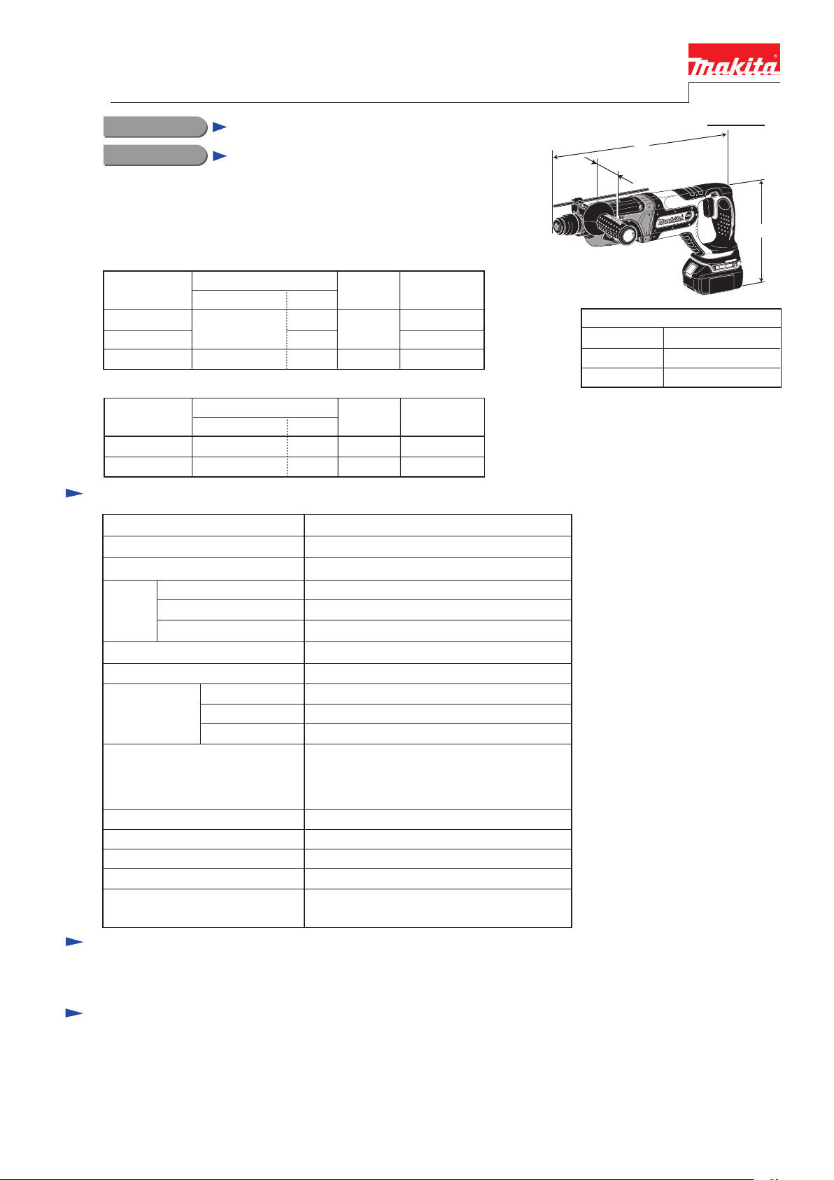
PRODUCT
P 1/ 14
L
W
Dimensions: mm (")
Length (L)
Width (W)*
Height (H)
* excludes Grip assembly
417 (16-3/8)
84 (3-5/16)
219 (8-5/8)
H
Specification
No load speed : (min -1= rpm)
Blows per min, :(bpm=min
Max. Output(W)
Voltage: V
Battery
Chuck Capacity: mm ( " )
Bit Shank
Capacity
: mm ( " )
Operation mode
R= Rotation only
H+R= Hammering with Rotation
H= Hammering only
Variable switch
Reverse switch
Clutch (Torque Limiter)
Electric Brake
Net Weight : kg (lbs)
Cell and Capacity
Charging Time: min.
Steel
Wood
* Concrete
0 - 1,100
-1)
3.2 (7.0) including Battery BL1830
[3.5 (7.7) measured by EPTA regulation]
0 - 4,000
330
18
Li-ion 3.0 Ah
22 with DC18RA
10 (3/8)
SDS-plus
13 (1/2)
26 (1-1/16)
20 (13/16)
3 modes
(R/ H+R/ H)
Yes
Yes
Yes
Yes
* Concrete: 24 (15/16)
for North America
Standard equipment
* Grip assembly ................................... 1 set * Depth gauge (Stopper pole) .............. 1 pc.
Note: The standard equipment for the tool shown above may differ by country.
Optional accessories
* SDS-Plus bits
* Taper shank T.C.T bits
* Taper shank adapter
* Cotter
* Drill chuck assembly
* Chuck adapter
* Drill chuck S13
* Chuck key S13
* Keyless drill chuck
* Grip assembly
* Scraper Assembly
* Cold chisels
* Grooving chisels
* Scaling chisels
* Bull points
* Dust Cup
* Grease Vessel 30g
* Blow out bulb
* Safety goggle
* Dust extractor attachment
* Joint 25
* Charger DC18RA
* Charger DC18SC
* Charger DC24SA
* Charger DC24SC
* Battery BL1830
* Hammer service kit
P 2/ 14
[1] NECESSARY REPAIRING TOOLS
CAUTION: Remove the battery and the bit from the machine for safety before
repair/ maintenance in accordance with the instruction manual!
Repair
DescriptionCode No.
1R003 Retaining ring S pliers SR-2 Removing / Installing Ring spring 19
Removing Ring spring 29
Removing Helical gear 25 from Cam shaft
Disassemble Oil seal 25 and Needle bearing complete from Gear housing
complete
Disassemble Ball bearing 608ZZ from Cam shaft
Installing Helical gear 25 to Cam shaft
Installing Oil seal 25 to Gear housing complete
Installing Oil seal 25 to Gear housing complete
Installing Needle bearing complete to Gear housing complete
Holding Tool holder complete
1R004 Retaining ring S pliers ST-2N
1R022
1R023
Bearing plate for Arbor press
Pipe ring (for Arbor press)
1R033
1R032
Bearing setting plate 10.2
Bearing setting plate 8.2
1R038 Armature holder 32 set for vise
1R164 Ring spring setting tool A
1R165 Ring spring setting tool B
1R212
Tip for Retaining ring pliers Attaching to 1R003 for removing Ring spring 19
1R232 Pipe 30
1R252 Round bar for Arbor 30-100
1R269 Bearing extractor
1R281 Round bar for Arbor 7-50
Removing Striker from Tool holder complete
Removing Ring 8 from Cam shaft
Removing / Installing Retaining ring S-7 from / to Cam shaft
Removing / Installing Ring spring 29 from / to Tool holder complete
1R291 Retaining ring S and R pliers
1R306 Ring spring removing jig
Use for
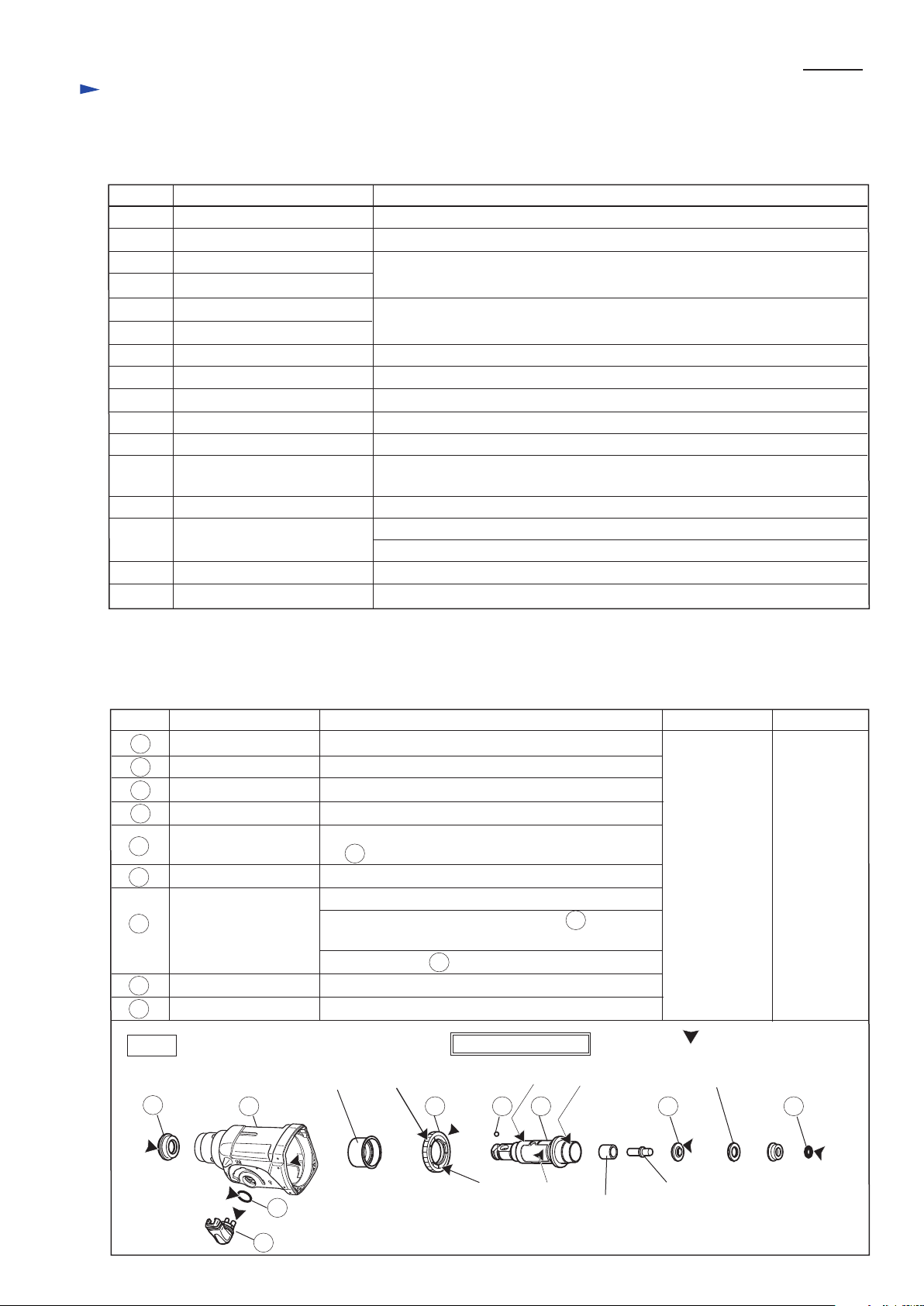
[2] LUBRICATION
Apply the following grease to protect parts and product from unusual abrasion.
* Makita grease R No.00 to the portions marked with black triangle
* Molybdenum disulfide lubricant to the portions marked with gray triangle
Fig. 1
Item No. Description Portion to lubricate Lubricant Amount
a little
1
(a) (c) (d)
(e)
16
17 28
Needle bearing
complete
29 30
13
34 37
Sleeve 9
Impact bolt
Cushion ring 13
(b)
Cap 35
O ring 17
1
16
Change lever
13
Gear housing complete
Spur gear 51
17
28
Steel ball 7
29
Tool holder complete
30
Lip portion where Bit is inserted
Whole portion
Pin portion
Inside where Swash bearing section rotates
(a) Teeth portion, (b) Surface where Clutch portion of
30 Tool holder complete contacts
Whole portion
(c) Surface where Needle bearing complete contacts
(d) Surface where Plane bearing 28 of 63 Inner
housing complete contacts
(e) Inside where 41 Piston cylinder reciprocates
Ring 10
34
O ring 9
Surface where Cushion ring 13 contacts
Whole portion
37
Tool Holder Section
Makita grease R No. 00
Makita grease R
No. 00
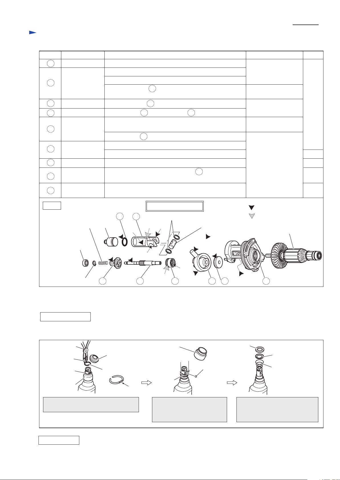
[2] LUBRICATION (cont.)
Repair
P 3/ 14
Fig. 2
Item No. Description Portion to lubricate Lubricant Amount
Striker
Ball bearing 606ZZ
Compression spring 7
Disassemble Tool holder section as illustrated in Fig. 3.
Retaining ring S-7
Piston joint
Armature
Flat washer 12
Swash Bearing Section
40
41
51
52 53
63
(f)
(g)
(h)
(g)
(k) Crank room
(i)
(j)
50
49
51
52
53
63
17
40
41
Clutch cam
Bearing portion
(k) Crank room
4g
17g
Swash bearing 10
Helical gear 25
Gear housing
complete
Inner housing
complete
O ring 16
Piston cylinder
Whole portion
Makita grease R No. 00
Makita grease R No. 00
Makita grease R No. 00
Molybdenum disulfide
lubricant
Molybdenum disulfide
lubricant
Molybdenum disulfide
lubricant
Makita grease R No. 00
a little
a little
5g
Pole portion which is inserted into Piston joint
49 Spur gear 10 Gear teeth where 28 Spur gear 51 engages (Refer to Fig. 1.)
Teeth portion
Space where Armature's drive end and 53 Helical gear 25
engages
(f) Inside where Striker moves
(g) Hole for accepting Piston joint
(h) Surface where 30 Tool holder complete contacts.
(Refer to Fig. 1.)
(i) Outside groove
(j) Side where 52 Swash bearing 10 engages
50 Cam shaft Surface where 51 Clutch cam and 49 Spur gear 10 contact
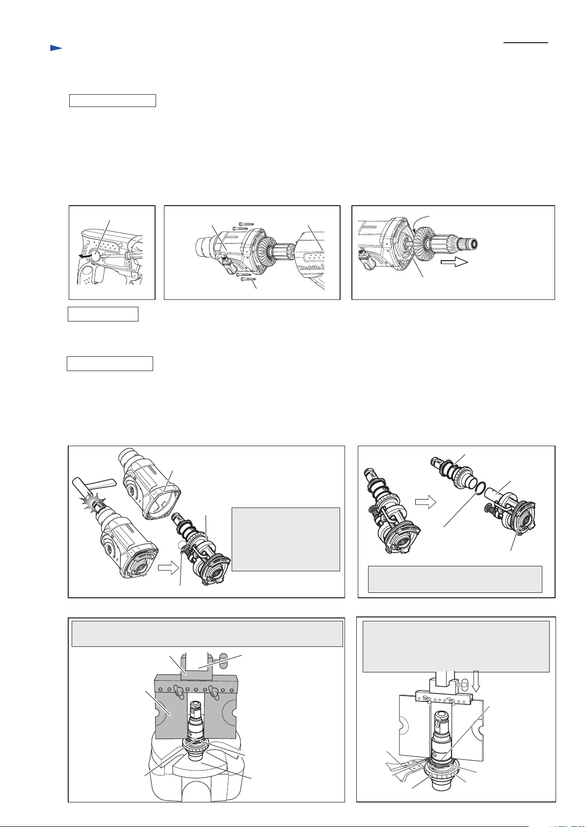
[3] DISASSEMBLY/ASSEMBLY
[3] -1. Tool Holder Section
DISASSEMBLING
Ring 21
Ring 21
Guide washer
Conical compression
spring 21-29
Cap 35
Steel ball 7.0
Chuck cover
Ring spring 19
Chuck cover
1R003
1R212
Disassemble Cap 35 and remove Ring
spring 19 with 1R003 and 1R212.
Note: Replace the tips of 1R003 to those
of 1R212.
Ring 21
Disassemble Chuck cover.
And remove Steel ball 7.0
while pressing down Ring 21.
After disassembling Steel ball 7.0,
the Tool holder section can be
disassembled as illustrated above.
Fig. 3
ASSEMBLING
Do the reverse of the disassembling step.
Note: Be sure to place the flat portion of Ring spring 19 on Steel ball 7.0. Refer to Fig. 3.
Flat portion
Repair
P 4/ 14
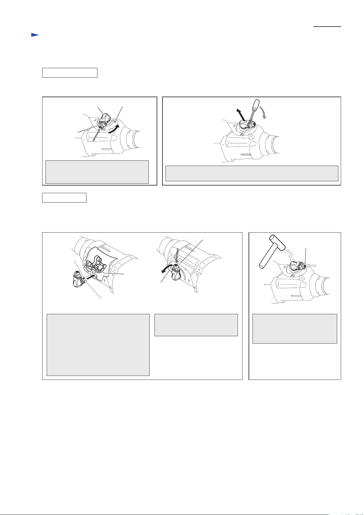
[3] DISASSEMBLY/ASSEMBLY
[3] -2. Change Lever
DISASSEMBLING
ASSEMBLING
Change lever Drill mode
Lock button
Pushing Lock button into Change lever,
turn Change lever fully to Drill mode
until it stops.
Remove Change lever by levering up it with Slotted head screwdriver,
inserted between Gear housing complete and Change lever.
Fig. 4 Fig. 5
Fig. 6 Fig. 7
Disassemble Change lever as illustrated in Figs. 4 and 5.
1) Assemble Change lever to Gear housing complete in the order of Figs. 6 and 7.
2) Make sure that Change lever stops at every operation mode exactly after assembling.
Lock plate
Drill mode
Hammer drill
mode
large pin of Change
lever
small pin
of Change
lever
Lock plate can be seen through the hole
for Change lever insertion before
mounting Change lever.
When inserting Change lever into Gear
housing complete, contact the small pin
to this Lock plate as designated in gray
color. Change lever can be inserted in
Hammer drill mode.
Pushing Lock button into Change
lever, turn Change lever fully
to Drill mode until it stops.
Pushing Lock button into Change
lever, tap Change lever.
Change lever can be assembled to
Gear housing complete.
Lock button
Repair
P 5/ 14
bearing room of
Gear housing complete
4x40 Tapping screws (4 pcs.)
Gear housing
complete
Holder cap cover Motor housing
complete
Ball bearing 6000DDW
of Armature (behind the Fan)
[3] DISASSEMBLY/ASSEMBLY
[3] -4. Armature
1) Remove Holder cap cover by inserting Slotted screwdriver between Holder cap cover and Motor housing complete.
(Fig. 8) Then remove Holder cap and Carbon brushes.
2) Seperate Gear housing complete from Motor housing complete by loosening 4x40 Tapping screws (4 pcs.).
Armature is left on Gear housing complete in this step. (Fig. 9)
3) Pull Armature out from Gear housing complete by hand. (Fig. 10) This way is easier than using Plastic hammer to strike
Gear housing portion. (Ball bearing 6000DDW of Armature is tightly fit into the bearing room in Gear housing complete
using O ring 26. )
Do the reverse of the disassembling step.
DISASSEMBLING
ASSEMBLING
Fig. 10Fig. 9Fig. 8
DISASSEMBLING
Fig. 11
Fig. 12
1) Disassemble Tool holder section as illustrated in Fig. 3.
2) Disassemble Change lever as illustrated in Figs.4 and 5.
3) Separate Gear housing complete from Motor housing. Then remove Armature from Gear housing complete. (Figs. 8 to 10)
4) Disassemble Torque limiter section as illustrated in Figs. 11 and 12.
5) Remove the Ring spring 29 to separate Washer 31, Compression spring 32 and Spur gear 51 (Figs. 13 and 14)
[3] -5. Torque Limiter Section
Remove Torque limiter section from Piston
cylinder and Inner housing complete.
Remove Torque limiter
section from Gear housing
complete by striking
Chuck assembling portion
with Plastic hammer.
Flat washer 28
Piston cylinder
Inner housing complete
Torque limiter section
Gear housing complete
Torque limiter
section
Ball bearing 606ZZ remains fixed in Gear housing complete.
Assemble two pcs. of 1R022 to 1R306 and hold them to the ram
of arbor press. Put Torque limiter section on the table of arbor press.
While compressing Compression spring 32 by
pressing down Washer 31 using arbor press,
remove Ring spring 29 using 1R004.
Spur gear 51 can be removed.
Washer 31
Washer 31
Ring spring 29
Compression spring 32
Ring spring 29
1R004
Table of arbor press
Fig. 13 Fig. 14
1R022 (2 pcs.)
1R036 ram of arbor press
Spur gear 51
 Loading...