

Makita BHR240, BHR240SFE, BHR240SF, BHR240Z Technical Information
T
ECHNICAL INFORMATION
Models No.
BHR240
PRODUCT
P 1 / 14
Description
Cordless Rotary Hammer
CONCEPT AND MAIN APPLICATIONS
The cordless version of HR2453/HR2454 has been launched
with D-handle for operator's comfort.
These new products will be available in the following variations.
Model No.
BHR240SFE
BHR240SF
BHR240Z
The variations for USA, Canada, Mexico and Panama are as follows.
Model No.
BHR240
BHR240Z
Specification
No load speed : (min -1= rpm)
Blows per min, :(bpm=min -1)
Max. Output(W)
Voltage: V
Battery
Chuck Capacity: mm ( " )
Bit Shank
Capacity
: mm ( " )
Working
mode
Variable switch
Reverse switch
Clutch (Torque Limiter)
Electric Brake
Net Weight : kg (lbs)
Cell and Capacity
Charging Time
Rotation
Rotation + Hammering
Hammering
Battery
Type Quantity
BL1830
No No No
Battery
Type Quantity
BL1830
No No No
Steel
Wood
* Concrete
Charger
2
DC18RA
1
---
Charger
DC18RA
2
---
Li-ion 3.0 Ah
approx. 22 min. with DC18RA
26 (1-1/16)
18 (11/16)
3.0 (6.6) including Battery BL1830
carrying case
carrying case
0 - 1,100
0 - 4,000
10 (3/8)
SDS plus
13 (1/2)
Yes
Yes
Yes
Yes
Yes
Yes
Yes
Plastic
Yes
Yes
Plastic
Yes
330
18
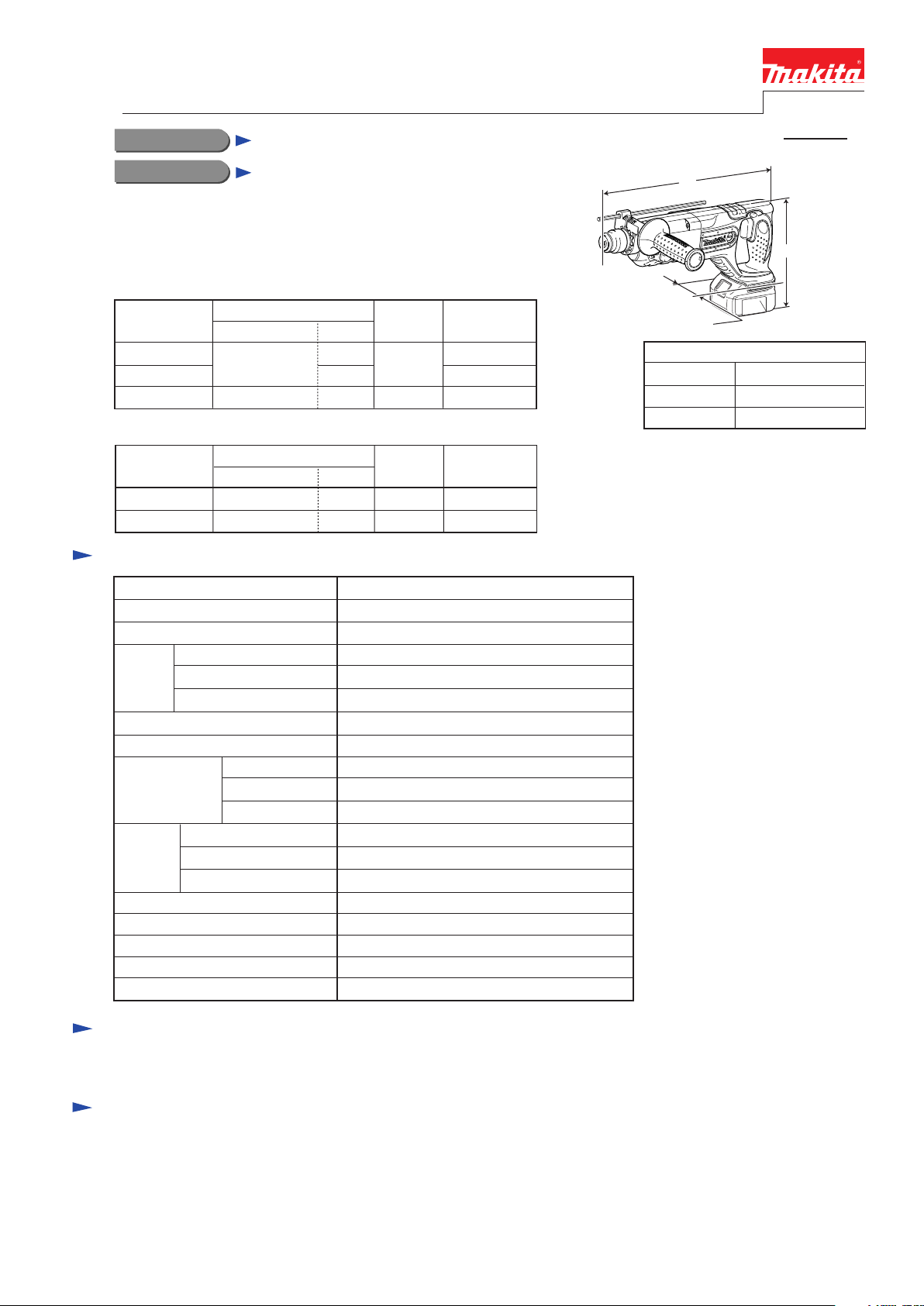
L
H
W
Dimensions: mm (")
Length (L)
Width (W)
Height (H)
* Concrete: 24 (7/8)
for North American Countries
410 (16-1/8)
78 (3-1/16)
206 (8-1/8)
Standard equipment
* Grip Assembly ................................... 1 set * Depth Gauge (Stopper Pole) .............. 1 pc.
Note: The standard equipment for the tool shown above may differ by country.
Optional accessories
* SDS-Plus bits
* Taper shank T.C.T bits
* Taper shank adapter
* Cotter
* Drill chuck assembly
* Chuck adapter
* Drill chuck S13
* Chuck key S13
* Keyless drill chuck
* Grip assembly
* Scraper Assembly
* Cold chisels
* Grooving chisels
* Scaling chisels
* Bull points
* Dust Cup
* Grease Vessel 30g
* Blow out bulb
* Safety goggle
* Dust extractor attachment
* Joint 25
* Charger DC18RA
* Charger DC18SC
* Charger DC24SA
* Charger DC24SC
* Battery BL1830

Repair
CAUTION: Remove the battery from the machine for safety before repair/ maintenance !
[1] NECESSARY REPAIRING TOOLS
Item No. Description Purpose
1R003
1R004 Retaining ring S pliers ST-2
1R023 Pipe ring Removing Helical gear 25
1R032 Bearing Setting Plate 8.2 Installing Helical gear 25
1R033 Bearing Setting Plate 10.2 Installing Helical gear 25
1R034 Bearing Setting Plate 12.2 Installing Helical gear 25
1R038 Armature holder 32 Fixing Tool holder
1R269 Bearing extractor Removing Ball bearing 608ZZ
1R281 Round bar arbor 7-50 Removing Ring 8
1R291 Retaining ring S and R pliers Removing Retaining ring S-7
1R306
Retaining ring S pliers ST-2N
Ring spring removing jig Removing Ring spring 29
Removing/ installing Ring spring 19
Removing/ installing Ring spring 29
Removing Helical gear 251R022 Bearing plate
Installing Needle bearing complete1R164 Ring spring setting tool A
Removing/ installing Ring spring 19 (for modular use with 1R003)1R212 Tip for retaining ring pliers
Installing Oil seal 251R232 Pipe 30
Removing Oil seal 251R252 Round bar for arbor
P 2 /14
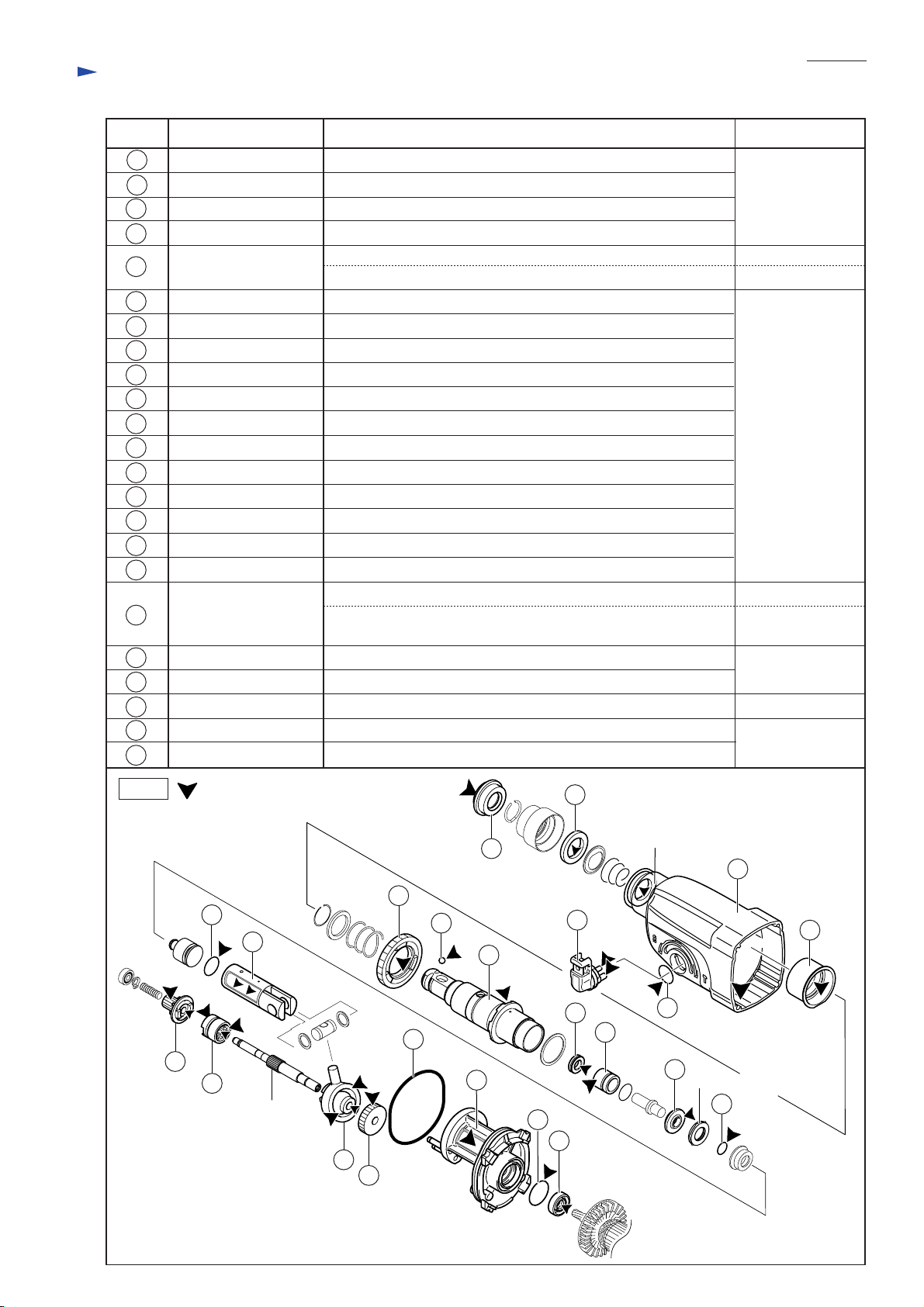
[2] LUBRICATION
Apply the following grease to the portions designated with the triangles to protect parts and product from unusual abrasion.
Item No. Description Portion to lubricate
29 Tool holder complete Whole inside surface
43
45
Flat washer 12 (2pcs)
44
50 Clutch cam
52
Fig. 1
Piston joint
Swash bearing 10 Pin portion that is inserted into 44 Piston joint
:Molybdenum disulfied grease
Whole surface
Whole surface
Groove
29
50
Piston cylinder
43
44
45
52
Repair
[2] -2. Makita Grease RB No.00
Item No. Amount to applyDescription Portion to lubricate
Cap 35 Inside surface that contacts hammer bit
1
Ring 21
4
13
17 Gear housing comp.
18
28
29 Tool holder comp.
31
35
42
52
65 Inner housing comp.
Change lever comp. Two pins
Needle bearing comp. Inside surface
Steel ball 7.0 Whole surface
X ring 9 Inner circumference
Ring 10 Surface that contacts Cushion ring 13
Piston cylinder Inside surface that contacts Striker
Swash bearing 10
Inner circumference that contacts Tool holder comp.
Whole surfaceO ring 1716
Gear room
Inner circumference of Oil seal
Inner circumference27 Spur gear 51
Face of cam and the surface that contacts Inner housing comp.
Surface that contacts Tool holder comp.32 Sleeve 9
Whole surface38 O ring 9
Whole surface41 O ring 16
Teeth portion and the inside surface that contacts Cam shaft49 Spur gear 10
Both faces of cam and the inside surface that contacts Cam shaft50 Clutch cam
Ball portion about 4g
Surface that contacts Helical gear 26 and the inside surface that
contacts Cam shaft
Teeth portion53 Helical gear 26
Whole surface48 O ring 63
Crank room where Piston cylinder thrusts
Whole surface66 O ring 24
Inner circumference that contacts Armature shaft67 Oil seal 8
P 3 /14
appropriate amount
about 17g
appropriate amount
appropriate amount
appropriate amount
appropriate amount
about 5g
appropriate amount
Fig. 2
:Makita grease RB No.00
41
42
49
50
Cam shaft
52
53
27
54
28
65
29
4
32
Oil seal
16
17
35
Cushion ring 13
38
18
1
13
31
66
67
Repair
[3] DISASSEMBLY/ASSEMBLY
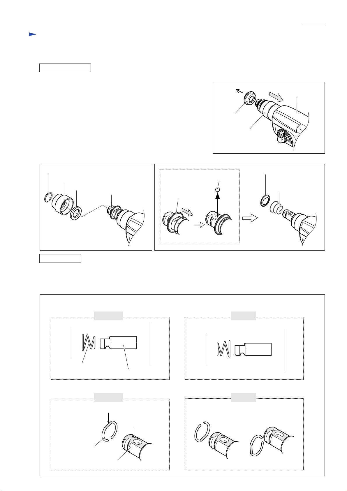
[3] -1. Chuck Section
DISASSEMBLING
1) Slide Chuck cover in the direction of Gear housing.
Remove Cap 35 using hand and a slotted screwdriver (Fig. 3).
2) Remove Ring spring 19 from the groove on Tool holder complete
using 1R003 and 1R212. Remove Ring spring 19.
Chuck cover and Ring 21 can now be removed (Fig. 4).
3) Pushing Guide washer in the direction of Gear housing,
remove Steel ball 7.0 from the slot on Tool holder complete.
Remove Guide washer and Conical compression spring 21-29 (Fig. 5).
P 4 /14
Fig. 3
Gear housing
Cap 35
Chuck cover
Fig. 4
Ring spring 19
Chuck cover
Ring 21
ASSEMBLING
Do the reverse of the disassembling steps.
Note: Conical compression spring 21-29 and Ring spring 19 are not reversible when assembled to Tool holder complete.
Be sure to assemble as illustrated in Fig. 6.
Fig. 6
Conical compression spring 21-29
Tool holder complete
Correct
Fig. 5
Guide washer
Steel ball 7.0
Guide washer
Conical compression
spring 21-29
Wrong
Cap 35 side
Conical compression
spring 21-29
Ring spring 19
Ring spring 19
Tool holder complete
Tool holder complete
Correct
flat portion
Gear housing side
flat portion
Cap 35 side
Gear housing side
Wrong
Repair
[3] DISASSEMBLY/ASSEMBLY
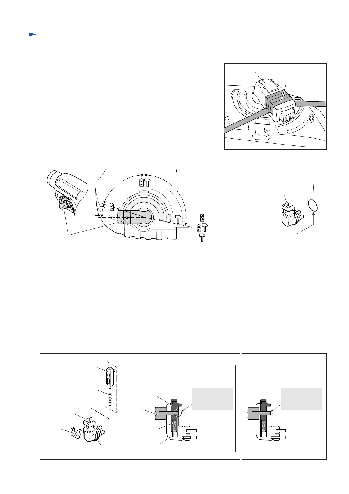
[3] -2. Change Lever
P 5 /14
Fig. 7
DISASSEMBLING
1) Lever up Cap from Change lever using two slotted screwdrivers (Fig. 7).
Note: Lock button and Compression spring 3 will fly away in this step.
Be careful not to lose them.
2) Rotate Change lever fully in the direction of the drill mode position until
the lever is located within the area B (Fig. 8). Change lever can now be
pulled off. Remove O ring 17 from Change lever (Fig. 9).
Fig. 8 Fig. 9
C
A
Change lever
Change lever
B
= Drill mode
= Rotary hammer mode
Change lever
= Hammer mode
Cap
O ring 17
ASSEMBLING
1) Apply grease to O ring 17 and the pins of Change lever as described in page 3.
2) Put Compression spring 3 and Lock button in place on Change lever. Assemble Cap provisionally to Change lever
as illustrated in Fig. 10 in order to prevent the spring from popping out from Change lever.
Do not forget to assemble O ring 17 to Change lever in this step.
3) Place the provisionally assembled Change lever within the area A of Gear housing (Fig. 8), and insert into the Change
lever installation hole. Change lever cannot be inserted completely in this step.
4) Pushing Change lever against Gear housing, turn Change lever in the direction of the drill mode until it reaches the
area B where it can be completely inserted into the hole. If cannot be completely inserted, do this operation with
Lock button pressed.
5) Turn Change lever to the area C (Fig. 8). Assemble Cap completely to Change lever by pushing in the direction of
Gear housing (Fig. 11).
Fig. 10 Fig. 11
Lock button
Compression spring 3
Change lever
Cap
Cap provisionally
assembled to Change lever
Lock button
Cap
Compression
spring 3
not protruding
from the surface
of Change lever
Cap completely
assembled to Change lever
protruding
from the surface
of Change lever
O ring 17
Change lever
 Loading...