

Makita BHP459, BDF459 Technical Information
Models No.
Description
PRODUCT
CONCEPT AND MAIN APPLICATIONS
P 1/ 11
BHP459
Cordless Hammer Driver Drill
Specification
Standard equipment
Optional accessories
Note: The standard equipment for the tool shown above may vary by country.
+ – bit 2-45 ........ 1
Belt clip .............. 1
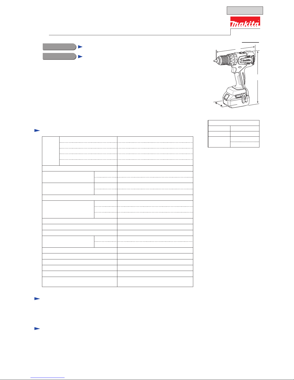
Dimensions: mm (")
Width (W)
Height (H)
Length (L)
192 (7-9/16)
78 (3-1/16)
238 (9-3/8)*
2
256 (10-1/8)*3
*2: with Battery BL1815
*3: with Battery BL1830
Li-ion Battery BL1830
Li-ion Battery BL1815
Drill bits for wood
Drill bits for steel
Phillips bits
Fast charger DC18RA
(for USA, Canada, Guam, Panama, Colombia, Mexico)
Fast charger DC18RC
(for all countries except the countries above)
Charger DC18SD
Charger DC24SC
Automotive charger DC18SE
[Drawn above is the image
with BL1830.]
Battery
Capacity of drill chuck: mm (")
Capacity: mm (")
Max lock torque: N.m (in.lbs)
Electric brake
Variable speed control
Mechanical speed control
Reversing switch
Max fastening torque:
N.m (in.lbs)
Torque setting
Steel
Wood
Soft joint
Hard joint
No load speed: min-
1=rpm
Energy capacity: Wh
Voltage: V
Capacity: Ah
High
Weight according to
EPTA-Procedure 01/2003: kg (lbs)
Low
Max output: W
24 (27*4)/ 54
Charging time (approx.): min.
Cell Li-ion
15/ 22 with DC18RC (DC18RA*1)
18
1.3 (1.5*
4)/ 3.0
Yes
Yes
Yes (2 speed)
Yes
Yes
1.5/ 1.7 (3.3/ 3.8)
13 (1/2)
38 (1-1/2)
16 stages + drill mode
Clutch torque setting: N.m (in.lbs)
1.0 - 5.0 (9 - 44)
45 (400)
25 (220)
45 (400)
0 - 1,500
0 - 400
1.5 (1/16) - 13 (1/2)
250
LED job light
T
ECHNICAL INFORMATION
Model BHP459 Cordless Hammer Driver Drill has been developed
specially for light to medium duty drilling and fastening applications.
This model is equipped with a basic BLDC motor (BrushLess DC motor) specially
designed to provide, above all, more work amount on a single full battery charge.
This product is powered by 18V-1.3(1.5*4)Ah/ 3.0Ah Li-ion batteries BL1815/ BL1830,
and available in the variations listed in the next page.
*
4 for some countries only
L
H
W
Impacts per minute:
min
ˉ¹=ipm
High
Low
0 - 22,500
0 - 6,000
Masonry 13 (1/2)
OFFICIAL USE
for ASC & Sales Shop

BHP459RFE
BHP459RF
Model No.
Type Quantity
Plastic
carrying
case
Battery
cover
Battery
No NoBHP459Z No
2 1
1 No
1 No
No
DC18RC
Charger
No
Yes
BL1830
BHP459RFE3
BHP459RH
BHP459RHE
BL1815 Yes
Yes
2 1
DC18RC
BHP459SHE 2 1DC18SD BL1815
BHP459
Housing
color
BHP459RFEW 2 1
Makita blue
Makita blue
Makita blue
White
Note: All models also include the accessories listed in "Standard equipment" of page 1.
3 2
Makita blue
Variation list
P 2/ 11
Repair
It is not required to lubricate the gear section because the portion is replaced as a factory- lubricated gear unit.
[3] DISASSEMBLY/ASSEMBLY
[3] -1. Drill Chuck
[1] NECESSARY REPAIRING TOOLS
CAUTION: Repair the machine in accordance with “Instruction manual” or “Safety instructions”.
Code No. Description Use for
1R359 Drill chuck removing tool
[2] LUBRICATION
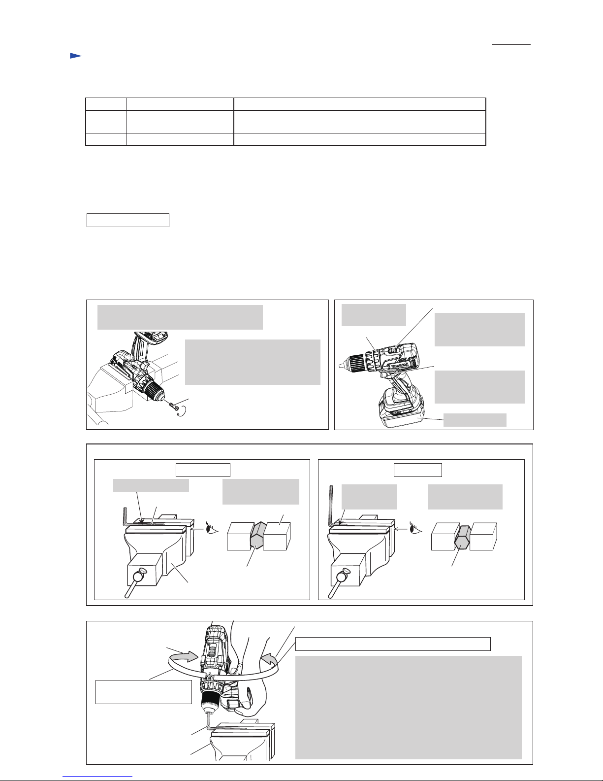
DISASSEMBLING
Hex wrench 10
(Use this tool if Drill chuck cannot be removed by the method of
described in “[3]-1 Drill chuck disassembling”.)
removing/ mounting Drill chuck
Fig. 1
M6x22 Flat head screw
(Left handed thread)
Note: It is required to remove Drill chuck when replacing Gear assembly, but you need not when replacing
the parts that are independent of Gear assembly.
(1) Remove M6x22 Flat head screw. (Fig. 1)
(2) Preset the machine. (Fig. 2) And set Hex wrench 10 to Vise. (Fig. 3)
(3) While holding Hex wrench 10 with Drill chuck firmly, remove Drill chuck from Gear assembly. (Fig. 4)
Fig. 2
Attach Battery.
F/R change lever
Set F/R Change lever
to Reverse (counter-
clockwise) rotation.
Set Speed change lever
to Low speed mode
designated with 1.
Speed change lever
Set Change ring
to Drill mode.
Change ring
Open Drill chuck fully and remove M6x22
Flat head screw by turning it clockwise.
CORRECT WRONG
Fig. 3
Fig. 4
Setting of Hex wrench10
Vise
Grip flat surfaces
of Hex wrench 10.
Hex wrench 10
Hex wrench 10,
viewed from side [A]
Vise
Hold the long end.
[A]
Do not hold edges
of Hex wrench 10.
Do not hold
the short end.
Hex wrench 10,
viewed from side [A]
Note: Use Impact driver to unscrew
M6x22 Flat head screw if it
could not be removed
manually.
[A]
Clockwise
Counterclockwise
Hex wrench 10
Vise
Clockwise*1 recoil force
of Machine
Note: The rotational direction is viewed from operator.
1. Hold Hex wrench 10 with Drill chuck and grip Machine.
Important:
Grip Machine tightly with both hands to provide
the sufficient counterclockwise*2 force against
clockwise*1 recoil force of Machine.
2. Pull Switch trigger slowly.
3. Spindle rotates counterclockwise*2 and consequently
Drill chuck is removed from spindle.
Counterclockwise*
2 force to be applied by operator
P 3/ 11
P 4/ 11
Repair
[3] DISASSEMBLY/ASSEMBLY
[3] -1. Drill Chuck (cont.)
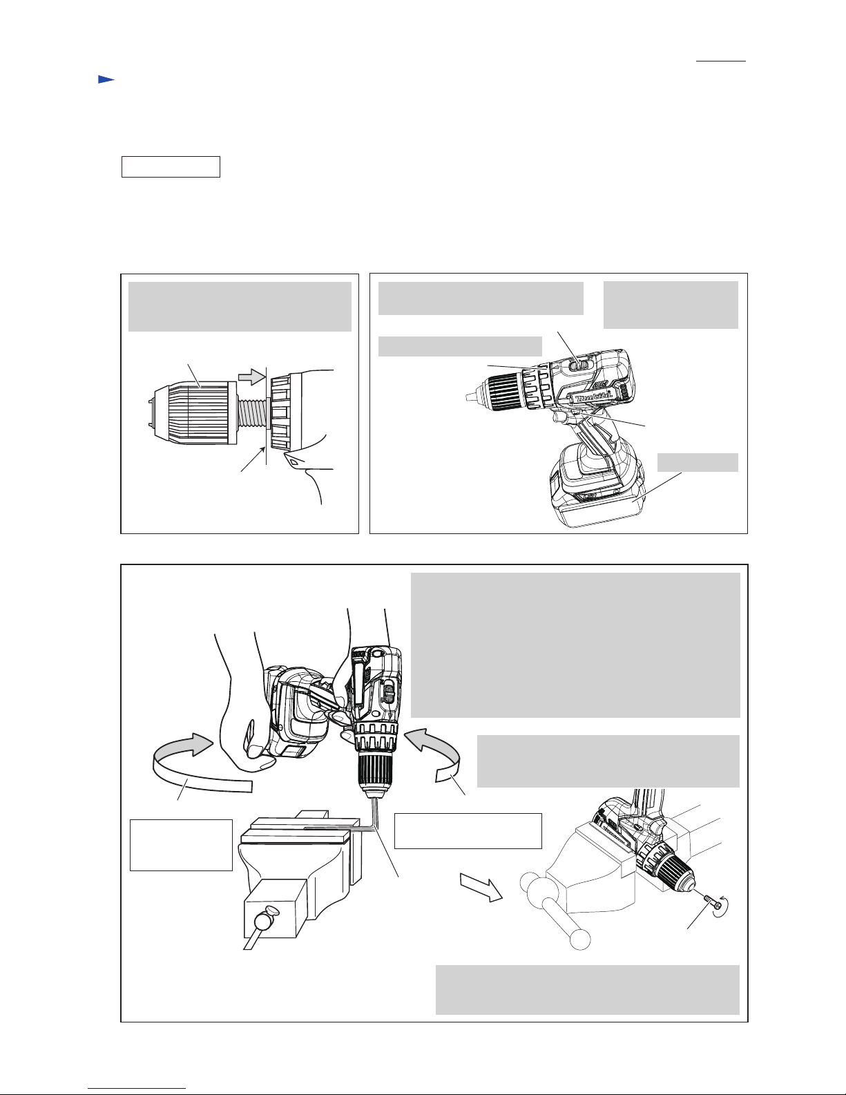
ASSEMBLING
Fig. 5
End of the threaded
portion of Spindle
Drill chuck
Fig. 6
Attach Battery.
F/R change lever
Set F/R Change lever
to Forward (clockwise)
rotation.
Set Speed change lever to Low speed
mode designated with 1.
Speed change lever
Set Change ring to Drill mode.
Change ring
Counterclockwise
Hex wrench 10
Fig. 7
Clockwise
4. Open Drill chuck fully, and tighten Drill chuck
with M6x22 Flat head screw by turning it
counterclockwise with Impact driver.
(1) Seat Drill chuck on Spindle. (Fig. 5)
(2) Set the machine to Drill mode, Low gear mode and Forward rotation mode. (Fig. 6)
(3) Set Hex wrench 10 to vise. (Refer to Fig. 3)
(4) Tighten Drill chuck. (Fig. 7)
M6x22 Flat head screw
(Left handed thread)
Turn Drill chuck clockwise by hand until
it is seated on the end of the threaded
portion of Spindle.
Note: Apply adhesive (ThreeBond 1342 or Loctite 242)
to threaded portion when re-using the removed
M6x22 Flat head screw.
Counterclockwise*
2 recoil
force of Machine
Note: The rotational direction is viewed from operator.
1. Hold Hex wrench 10 with Drill chuck and grip Machine.
Important: Grip Machine hard with both hands to provide
sufficient clockwise*1 force against
counterclockwise*2 recoil force of Machine.
2. Pull Switch trigger slowly to turn Spindle clockwise*1.
Note: Pull the Trigger so that Spindle’s rotating reaches full
speed in one second.
3. Drill chuck is tightened and consequently Spindle is locked.
Clockwise*
1 force
to be applied
by operator
 Loading...