

Makita BDF456, BHP456RHE, BHP456RHEW, BHP456RFE, BHP456RFEW Technical Information
...
P 1/10
Model No.
Description
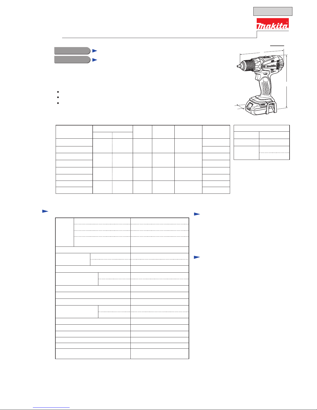
CONCEPT AND MAIN APPLICATIONS
Specification
Dimensions: mm (")
Width (W)
Height (H)
Length (L)
192 (7-9/16)
79 (3-1/8)
234 (9-1/4)*
2
251 (9-7/8)*3
BDF456
Cordless Driver Drill
Battery
Capacity of drill chuck: mm (")
Capacity: mm (")
Lock torque: N.m (in.lbs)
Electric brake
Variable speed control
Mechanical speed control
Reversing switch
Max. fastening
torque: N.m (in.lbs)
Torque setting
Steel
Wood
Soft joint
Hard joint
No load speed:
min-
1=rpm
Cell
Voltage: V
Capacity: Ah
High
Standard equipment
Optional accessories
Note: The standard equipment for the tool
shown above may differ by country.
Fast charger DC18RA
Charger DC18SD
Charger DC24SC
Automotive Charger DC18SE
Battery BL1815
Battery BL1830
Drill bits for wood
Drill bits for steel
Belt clip
Bit holder
+ - bit 2-45 ........ 1 pc
Belt clip ............ 1 pc
Weight according to
EPTA-Procedure 01/2003*4: kg (lbs)
Low
Max output: W
Li-ion
Charging time (approx.):
min.
15/ 22
with DC18RA
18
1.3/ 3.0
Yes
Yes
Yes (2 speed)
Yes
Yes
1.5 (3.3)*
2/ 1.7 (3.8)*3
13 (1/2)
38 (1-1/2)
16 stage + drill mode
Clutch torque setting: N.m (in.lbs)
1.0 - 5.0 (9 - 44)
54 (480)
36 (320)
50 (440)
0 - 1,500
0 - 400
1.5 (1/16) - 13 (1/2)
300
Model BDF456 is the upgraded version of model BDF452, featuring:
More compact and lightweight design than BDF452
More comfortable operation will be provided by re-designed ergonomic grip
Compatible with the 18V Li-ion batteries equipped with the Battery protection circuit
designed to protect the battery from damages due to overdischarge, high temperature
or overload current
This product is available in the following variations.
All models also include the accessories listed below in "Standard equipment".
Housing
color
*2: with Battery BL1815
*3: with Battery BL1830
BDF456RFE
BDF456RFEW
DC18RA
Model No.
Type Quantity
Charger
Plastic
carrying case
Battery
cover
Yes
No
2
Battery
BDF456Z
BL1815 DC18RA Yes
BDF456RHE
BL1830
2
1
No No
1
BDF456SHE
DC18SD Yes2
BL1815 1
BDF456SHEW
BDF456ZW
Makita blue
white
Makita blue
Makita blue
white
white
No No
Makita blue
whiteBDF456RHEW
*2 with Battery BL1815, *3 with Battery BL1830
*4 with the lightest battery available for the model
PRODUCT
LED job light
(with Battery BL1815)
W
L
H
T
ECHNICAL INFORMATION
OFFICIAL USE
for ASC & Sales Shop
P 2/10
Repair
CAUTION: Repair the machine in accordance with “Instruction manual” or “Safety instructions”.
[1] NECESSARY REPAIRING TOOLS
[2] LUBRICATIONS
[3] DISASSEMBLY/ASSEMBLY
[3]-1. Drill chuck
Code No.
1R359
Description Use for
Hex wrench 10 Removing / Assembling drill chuck
Drill chuck removing tool
Removing Drill chuck
(Use this tool if Drill chuck cannot be removed by the method
described in “ [3]-1. Drill chuck disassembling”.)
DISASSEMBLING
Lubrications are not required as Gear section is replaced as a factory-lubricated gear unit.
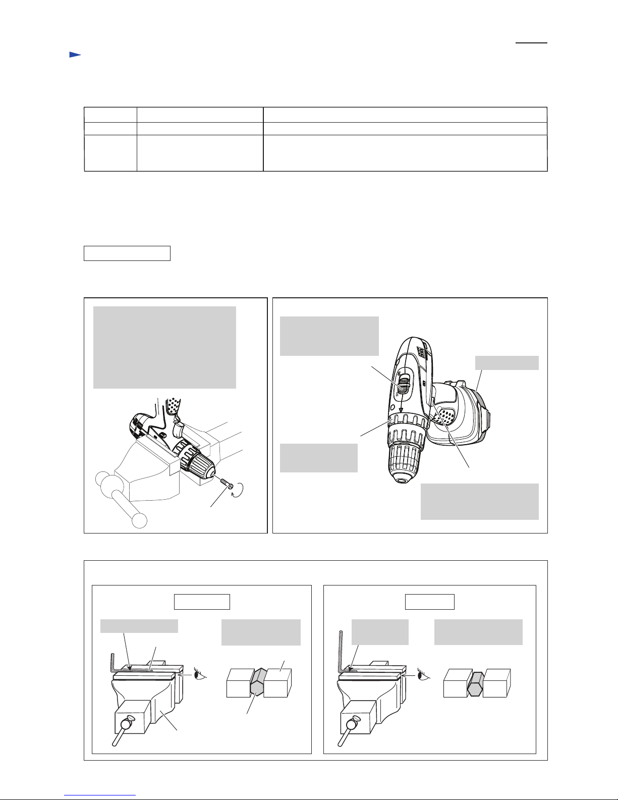
(1) Set Machine and Repairing tools. (Figs. 1, 2, 3)
CORRECT WRONG
Fig. 3
Fig. 1 Fig. 2
Note:
Use Impact driver to unscrew
M6 x 22 Flat head screw if it
could not be removed manually.
Open Keyless drill chuck fully and
remove M6 x 22 Flat head screw
by turning it clockwise.
M6 x 22 Flat head screw
F/R Change lever
Set Speed change lever
to Low speed mode
indicated by "1".
Set Change ring
to Drill mode.
Speed change lever
Change ring
Set F/R Change lever to
Reverse (counterclockwise)
rotation.
Attach battery.
Setting of Hex wrench 10
Vise
Grip flat surfaces
of Hex wrench 10.
Hex wrench 10
Hex wrench 10,
viewed from side [A]
Vise
Grip the long end.
[A]
Do not grip edges of
Hex wrench.
Do not grip
the short end.
P 3/10
Repair
[3] DISASSEMBLY/ASSEMBLY
[3]-1. Drill chuck (cont.)
DISASSEMBLING
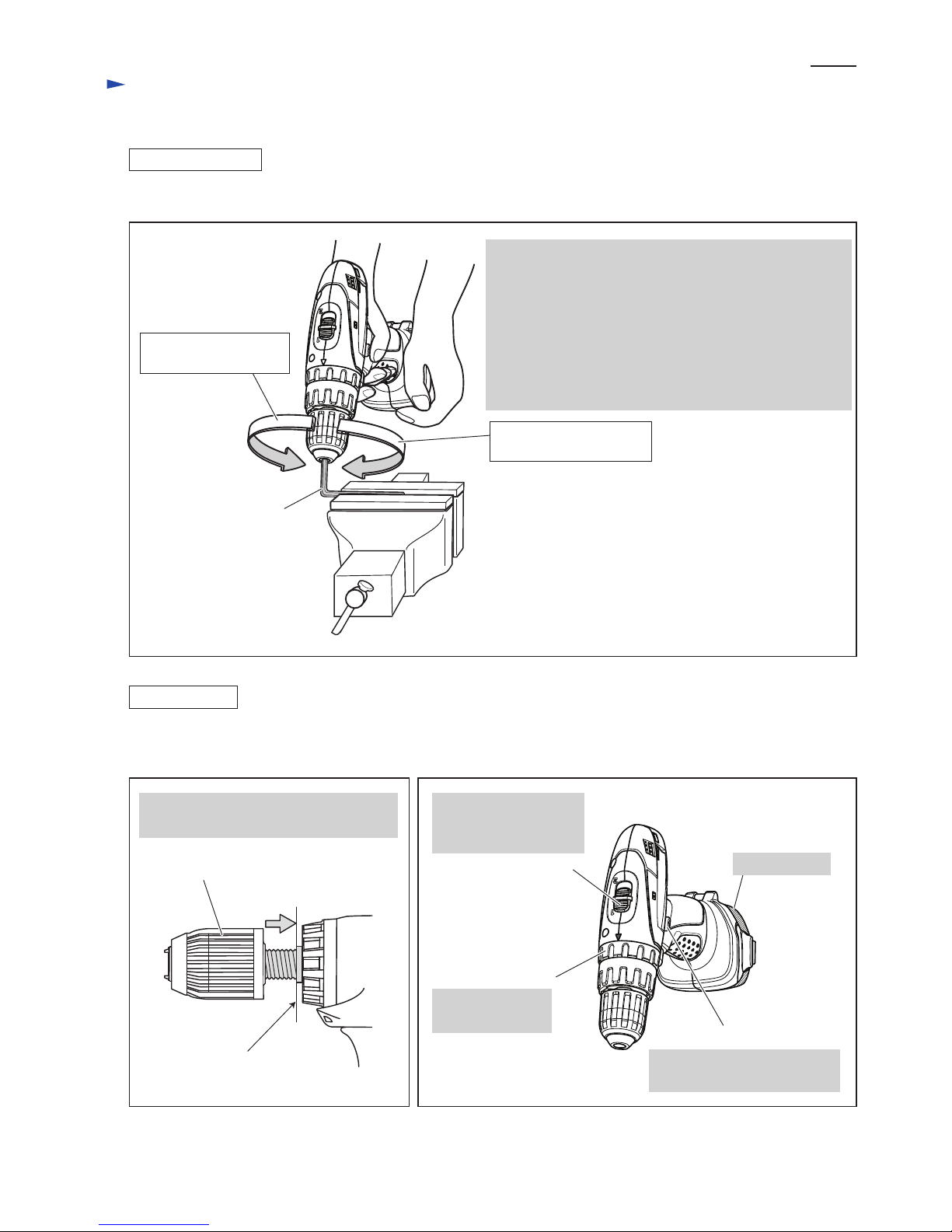
(2) Remove Drill chuck. (Fig. 4)
*Note: The rotational direction is viewed from operator.
1. Grip Hex wrench 10 with Drill chuck and hold Machine.
Important:
Be sure to hold the grip of Machine tightly with sufficient
counterclockwise* force against clockwise* recoil force
of Machine.
2. Pull Switch trigger slowly.
3. Spindle rotates counterclockwise* and consequently
Drill chuck is removed from spindle.
Hex wrench 10
Fig. 4
ASSEMBLING
Fig. 5 Fig. 6
end of the threaded
portion of Spindle
Drill chuck
(1) Set the machine. (Figs. 5, 6)
(2) Set Hex wrench 10 to vise as described in Fig. 3.
Turn Drill chuck clockwise until it sits on
the end of the threaded portion of Spindle.
F/R Change lever
Set Speed change lever
to Low speed mode
indicated by "1".
Set Change ring
to Drill mode.
Speed change lever
Change ring
Set F/R Change lever to
Forward (clockwise) rotation.
Attach battery.
Counterclockwise* force
to be applied by operator
Clockwise* recoil force
of Machine
 Loading...