

Makita BHP451, BHP441 User Manual
INSTRUCTION MANUAL
MANUEL D'INSTRUCTION
MANUAL DE INSTRUCCIONES
Cordless Hammer Driver-Drill
Perceuse - tournevis perforateur
sans fil
Taladro-Destornillador de Impacto
Inalámbrico
BHP441
BHP451
006749
WARNING:
For your personal safety, READ and UNDERSTAND before using.
SAVE THESE INSTRUCTIONS FOR FUTURE REFERENCE.
AVERTISSEMENT:
Pour votre propre sécurité, prière de lire attentivement avant l’utilisation.
GARDER CES INSTRUCTIONS POUR RÉFÉRENCE ULTÉRIEURE.
ADVERTENCIA:
Para su seguridad personal, LEA DETENIDAMENTE este manual antes de usar la herramienta.
GUARDE ESTAS INSTRUCCIONES PARA FUTURA REFERENCIA.

ENGLISH
SPECIFICATIONS
Model BHP441 BHP451
Concrete 14 mm (9/16”) 16 mm (5/8”)
Steel 13 mm (1/2”) 13 mm (1/2”)
Capacities
No load speed (RPM)
Blows per minute
Overall length 250 mm (9-7/8”) 250 mm (9-7/8”)
Net weight 2.1 kg (4.6 lbs) 2.2 kg (4.9 lbs)
Rated voltage D.C. 14.4 V D.C. 18 V
Standard battery cartridges BL1430 BL1830
• Due to our continuing programme of research and development, the specifications herein are subject to change
without notice.
• Note: Specifications may differ from country to country.
Wood 50 mm (2”) 65 mm (2-9/16”)
Wood screw 6 mm x 75 mm (1/4” x 2-15/16”) 10 mm x 89 mm (3/8” x 3-1/2”)
Machine screw 6 mm ( 1/4 “) 6 mm ( 1/4 “)
High (3) 0 - 1,700/min.
Medium (2) 0 - 600/min.
Low (1) 0 - 300/min.
High (3) 0 - 25,500/min.
Meduim (2) 0 - 9,000/min.
Low (1) 0 - 4,500/min.
GENERAL SAFETY RULES
GEA002-3
WARNING:
Read all instructions. Failure to follow all
instructions listed below may result in
electric shock, fire and/or serious injury. The
term “power tool” in all of the warnings listed
below refers to your mains-operated
(corded) power tool or battery-operated
(cordless) power tool.
SAVE THESE INSTRUCTIONS
Work area safety
1. Keep work area clean and well lit. Cluttered and
dark areas invite accidents.
2. Do not operate power tools in explosive atmo-
spheres, such as in the presence of flammable
liquids, gases or dust. Power tools create sparks
which may ignite the dust or fumes.
3. Keep children and bystanders away while operating a power tool. Distractions can cause you to
lose control.
Electrical safety
4. Power tool plugs must match the outlet. Never
modify the plug in any way. Do not use any
adapter plugs with earthed (grounded) power
tools. Unmodified plugs and matching outlets will
reduce risk of electric shock.
5. Avoid body contact with earthed or grounded
surfaces such as pipes, radiators, ranges and
refrigerators. There is an increased risk of electric
shock if your body is earthed or grounded.
6. Do not expose power tools to rain or wet conditions. Water entering a power tool will increase the
risk of electric shock.
7. Do not abuse the cord. Never use the cord for
carrying, pulling or unplugging the power tool.
Keep cord away from heat, oil, sharp edges or
moving parts. Damaged or entangled cords
increase the risk of electric shock.
8. When operating a power tool outdoors, use an
extension cord suitable for outdoor use. Use of a
cord suitable for outdoor use reduces the risk of
electric shock.
2

Personal safety
9. Stay alert, watch what you are doing and use
common sense when operating a power tool. Do
not use a power tool while you are tired or under
the influence of drugs, alcohol or medication. A
moment of inattention while operating power tools
may result in serious personal injury.
10. Use safety equipment. Always wear eye protection. Safety equipment such as dust mask, non-skid
safety shoes, hard hat, or hearing protection used
for appropriate conditions will reduce personal injuries.
11. Avoid accidental starting. Ensure the switch is in
the off-position before plugging in. Carrying
power tools with your finger on the switch or plugging in power tools that have the switch on invites
accidents.
12. Remove any adjusting key or wrench before
turning the power tool on. A wrench or a key left
attached to a rotating part of the power tool may
result in personal injury.
13. Do not overreach. Keep proper footing and balance at all times. This enables better control of the
power tool in unexpected situations.
14. Dress properly. Do not wear loose clothing or
jewellery. Keep your hair, clothing, and gloves
away from moving parts. Loose clothes, jewellery
or long hair can be caught in moving parts.
15. If devices are provided for the connection of
dust extraction and collection facilities, ensure
these are connected and properly used. Use of
these devices can reduce dust-related hazards.
Power tool use and care
16. Do not force the power tool. Use the correct
power tool for your application. The correct power
tool will do the job better and safer at the rate for
which it was designed.
17. Do not use the power tool if the switch does not
turn it on and off. Any power tool that cannot be
controlled with the switch is dangerous and must be
repaired.
18. Disconnect the plug from the power source and/
or the battery pack from the power tool before
making any adjustments, changing accessories,
or storing power tools. Such preventive safety
measures reduce the risk of starting the power tool
accidentally.
19. Store idle power tools out of the reach of children and do not allow persons unfamiliar with
the power tool or these instructions to operate
the power tool. Power tools are dangerous in the
hands of untrained users.
20. Maintain power tools. Check for misalignment or
binding of moving parts, breakage of parts and
any other condition that may affect the power
tools operation. If damaged, have the power tool
repaired before use. Many accidents are caused by
poorly maintained power tools.
21. Keep cutting tools sharp and clean. Properly
maintained cutting tools with sharp cutting edges
are less likely to bind and are easier to control.
22. Use the power tool, accessories and tool bits
etc. in accordance with these instructions and in
the manner intended for the particular type of
power tool, taking into account the working conditions and the work to be performed. Use of the
power tool for operations different from those
intended could result in a hazardous situation.
Battery tool use and care
23. Ensure the switch is in the off position before
inserting battery pack. Inserting the battery pack
into power tools that have the switch on invites accidents.
24. Recharge only with the charger specified by the
manufacturer. A charger that is suitable for one
type of battery pack may create a risk of fire when
used with another battery pack.
25. Use power tools only with specifically designated battery packs. Use of any other battery
packs may create a risk of injury and fire.
26. When battery pack is not in use, keep it away
from other metal objects like paper clips, coins,
keys, nails, screws, or other small metal objects
that can make a connection from one terminal to
another. Shorting the battery terminals together
may cause burns or a fire.
27. Under abusive conditions, liquid may be ejected
from the battery, avoid contact. If contact accidentally occurs, flush with water. If liquid contacts eyes, additionally seek medical help. Liquid
ejected from the battery may cause irritation or
burns.
Service
28. Have your power tool serviced by a qualified
repair person using only identical replacement
parts. This will ensure that the safety of the power
tool is maintained.
29. Follow instruction for lubricating and changing
accessories.
30. Keep handles dry, clean and free from oil and
grease.
SPECIFIC SAFETY RULES
GEB003-2
DO NOT let comfort or familiarity with
product (gained from repeated use)
replace strict adherence to hammer drill
safety rules. If you use this power tool
3

unsafely or incorrectly, you can suffer
serious personal injury.
1. Wear ear protectors with impact drills. Exposure
to noise can cause hearing loss.
2. Use auxiliary handles supplied with the tool.
Loss of control can cause personal injury.
3. Hold power tools by insulated gripping surfaces
when performing an operation where the cutting
tool may contact hidden wiring or its own cord.
Contact with a “live” wire will make exposed metal
parts of the tool “live” and shock the operator.
4. Always be sure you have a firm footing.
Be sure no one is below when using the tool in
high locations.
5. Hold the tool firmly with both hands.
6. Keep hands away from rotating parts.
7. Do not leave the tool running. Operate the tool
only when hand-held.
8. Do not touch the bit or the workpiece immediately after operation; they may be extremely hot
and could burn your skin.
9. Some material contains chemicals which may be
toxic. Take caution to prevent dust inhalation
and skin contact. Follow material supplier safety
data.
SAVE THESE INSTRUCTIONS
WARNING:
MISUSE or failure to follow the safety
rules stated in this instruction manual
may cause serious personal injury.
SYMBOLS
The followings show the symbols used for tool.
V............................volts
....................direct current
.....................no load speed
.../min....................revolutions or reciprocation per
minute
.....................number of blow
USD302-1
IMPORTANT SAFETY
INSTRUCTIONS FOR BATTERY
CARTRIDGE
1. Before using battery cartridge, read all instructions and cautionary markings on (1) battery
charger, (2) battery, and (3) product using battery.
2. Do not disassemble battery cartridge.
3. If operating time has become excessively
shorter, stop operating immediately. It may
result in a risk of overheating, possible burns
and even an explosion.
4. If electrolyte gets into your eyes, rinse them out
with clear water and seek medical attention right
away. It may result in loss of your eyesight.
5. Do not short the battery cartridge:
(1) Do not touch the terminals with any conduc-
tive material.
(2) Avoid storing battery cartridge in a con-
tainer with other metal objects such as nails,
coins, etc.
(3) Do not expose battery cartridge to water or
rain.
A battery short can cause a large current flow,
overheating, possible burns and even a breakdown.
6. Do not store the tool and battery cartridge in
locations where the temperature may reach or
exceed 50°C (122°F).
7. Do not incinerate the battery cartridge even if it
is severely damaged or is completely worn out.
The battery cartridge can explode in a fire.
8. Be careful not to drop or strike battery.
ENC007-1
SAVE THESE INSTRUCTIONS
Tips for maintaining maximum battery
life
1. Charge the battery cartridge before completely
discharged.
Always stop tool operation and charge the battery cartridge when you notice less tool power.
2. Never recharge a fully charged battery cartridge.
Overcharging shortens the battery service life.
3. Charge the battery cartridge with room temperature at 10°C - 40°C (50°F - 104°F). Let a hot battery cartridge cool down before charging it.
4. Charge the Lithium-ion battery cartridge when
you do not use it for more than six months.
4
FUNCTIONAL DESCRIPTION
CAUTION:
• Always be sure that the tool is switched off and the
battery cartridge is removed before adjusting or
checking function on the tool.
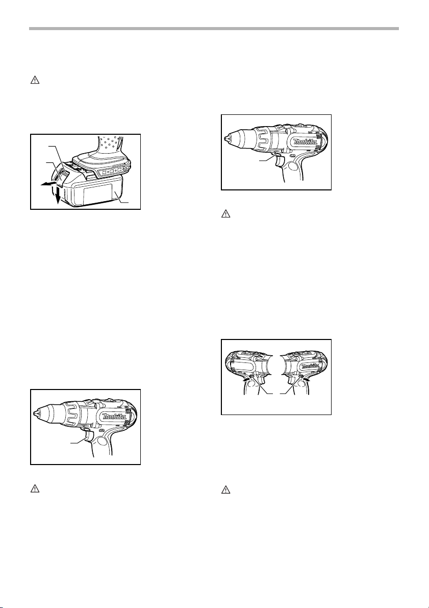
Installing or removing battery cartridge
1
2
• Always switch off the tool before insertion or
removal of the battery cartridge.
• To remove the battery cartridge, withdraw it from
the tool while sliding the button on the front of the
cartridge.
• To insert the battery cartridge, align the tongue on
the battery cartridge with the groove in the housing
and slip it into place. Always insert it all the way
until it locks in place with a little click. If you can see
the red part on the upper side of the button, it is not
locked completely. Insert it fully until the red part
cannot be seen. If not, it may accidentally fall out of
the tool, causing injury to you or someone around
you.
• Do not use force when inserting the battery
cartridge. If the cartridge does not slide in easily, it
is not being inserted correctly.
Switch action
006717
3
006750
1. Red part
2. Button
3. Battery cartridge
1. Switch trigger
Electric brake
This tool is equipped with an electric brake. If the tool
consistently fails to quickly stop after switch trigger
release, have tool serviced at a Makita service center.
Lighting up the front lamp
1
CAUTION:
• Do not look in the light or see the source of light
directly.
Pull the switch trigger to light up the lamp. The lamp
keeps on lighting while the switch trigger is being pulled.
The lamp goes out 10 -15 seconds after releasing the
trigger.
NOTE:
• Use a dry cloth to wipe the dirt off the lens of lamp.
Be careful not to scratch the lens of lamp, or it may
lower the illumination.
Reversing switch action
A
1
006751
1. Lamp
006752
1. Reversing
switch lever
B
1
CAUTION:
• Before inserting the battery cartridge into the tool,
always check to see that the switch trigger actuates
properly and returns to the “OFF” position when
released.
To start the tool, simply pull the switch trigger. Tool speed
is increased by increasing pressure on the switch trigger.
Release the switch trigger to stop.
This tool has a reversing switch to change the direction of
rotation. Depress the reversing switch lever from the “A”
side for clockwise rotation or from the “B” side for counterclockwise rotation.
When the reversing switch lever is in the neutral position,
the switch trigger cannot be pulled.
CAUTION:
• Always check the direction of rotation before
operation.
• Use the reversing switch only after the tool comes
to a complete stop. Changing the direction of
rotation before the tool stops may damage the tool.
• When not operating the tool, always set the
reversing switch lever to the neutral position.
5
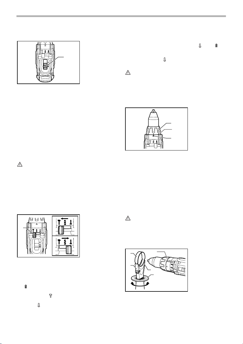
Speed change
This tool has a three-gear speed change lever. To
change the speed, first switch off the tool and then slide
the speed change lever to the “1” position for low speed,
“2” position for medium speed or “3” position for high
speed. Be sure that the speed change lever is set to the
correct position before operation. Use the right speed for
your job.
NOTE:
• When changing the position from “1” to “3” or from
“3” to “1”, it may be a little difficult to slide the speed
change lever. At this time, switch on and run the
tool for a second at the “2” position, then stop the
tool and slide to your desired position.
CAUTION:
• Always set the speed change lever fully to the
correct position. If you operate the tool with the
speed change lever positioned halfway between the
“1” position, “2” position and “3” position, the tool
may be damaged.
• Do not use the speed change lever while the tool is
running. The tool may be damaged.
Selecting the action mode
1
This tool employs an action mode change lever. Select
one of the three modes suitable for your work needs by
using this lever.
For rotation only, slide the lever so that it points toward
the mark on the tool body.
For rotation with hammering, slide the lever so that it
points toward the mark on the tool body.
For rotation with clutch, slide the lever so that the it points
toward the mark on the tool body.
006753
1. Speed change
lever
1
006757
1. Action mode
change lever
NOTE:
• When changing the position from “ “ to “ “, it
may be a little difficult to slide the mode change
lever. At this time, switch on and run the tool for a
second at the “ “ position, then stop the tool and
slide to your desired position.
CAUTION:
• Always set the lever correctly to your desired mode
mark. If you operate the tool with the lever
positioned halfway between the mode marks, the
tool may be damaged.
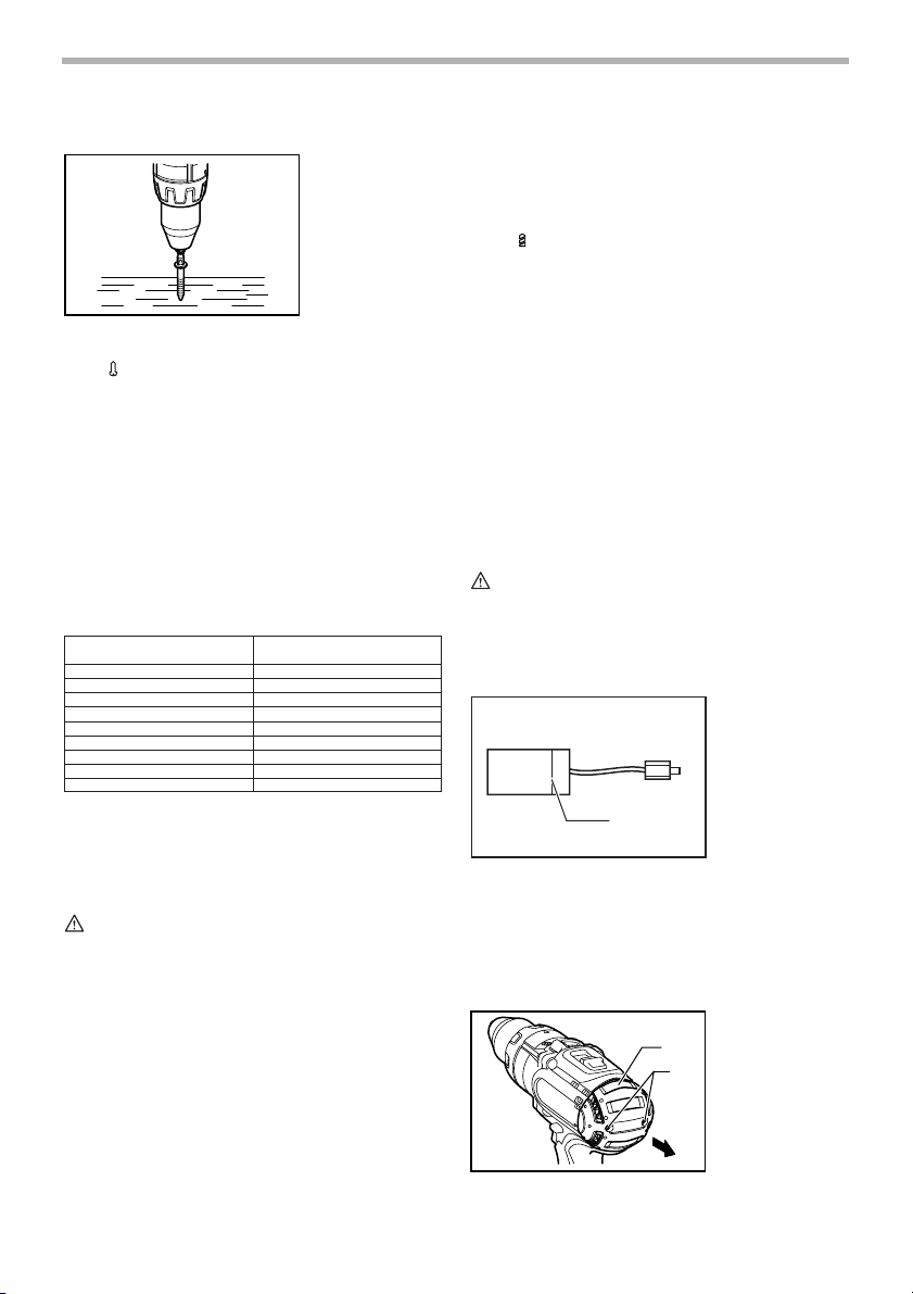
Adjusting the fastening torque
The fastening torque can be adjusted in 16 steps by turning the adjusting ring so that its graduations are aligned
with the arrow on the tool body. The fastening torque is
minimum when the number 1 is aligned with the arrow,
and maximum when the number 16 is aligned with the
arrow.
Before actual operation, drive a trial screw into your
material or a piece of duplicate material to determine
which torque level is required for a particular application.
006754
1. Adjusting ring
2. Arrow
1
3
2
3. Graduations
ASSEMBLY
CAUTION:
• Always be sure that the tool is switched off and the
battery cartridge is removed before carrying out
any work on the tool.
Installing side grip (auxiliary handle)
1
2
Always use the side grip to ensure operating safety.
Insert the side grip so that the protrusions on the grip
base fit in between the grooves on the tool barrel. Then
tighten the grip by turning clockwise.
5
3
4
6
006758
1. Steel band
2. Grip base
3. Protrusion
4. Side grip
5. Groove
Installing or removing driver bit or drill bit
006755
1. Sleeve
1
Hook
006727
1. Screw
2. Hook
3. Groove
1
3
2
Turn the sleeve counterclockwise to open the chuck jaws.
Place the bit in the chuck as far as it will go. Turn the
sleeve clockwise to tighten the chuck.
To remove the bit, turn the sleeve counterclockwise.
Installing bit holder
1
2
Fit the bit holder into the protrusion at the tool foot on
eithher right or left side and secure it with a screw.
When not using the driver bit, keep it in the bit holders.
Bits 45 mm (1-3/4”) )long can be kept there.
Adjustable depth rod
1
2
The adjustable depth rod is used to drill holes of uniform
depth. Loosen the clamp screw, set to desired position,
then tighten the clamp screw.
006725
1. Bit holder
2. Bit
006759
1. Depth rod
2. Clamp screw
The hook is convenient for temporarily hanging the tool.
This can be installed on either side of the tool.
To install the hook, insert it into a groove in the tool housing on either side and then secure it with a screw. To
remove, loosen the screw and then take it out.
OPERATION
Hammer drilling operation
CAUTION:
• There is a tremendous and sudden twisting force
exerted on the tool/bit at the time of hole breakthrough, when the hole becomes clogged with
chips and particles, or when striking reinforcing
rods embedded in the concrete. Always use the
side grip (auxiliary handle) and firmly hold the tool
by both side grip and switch handle during
operations. Failure to do so may result in the loss of
control of the tool and potentially severe injury.
First, slide the action mode change lever so that it points
to the marking. The adjusting ring can be aligned in
any torque levels for this operation.
Be sure to use a tungsten-carbide tipped bit.
Position the bit at the desired location for the hole, then
pull the switch trigger. Do not force the tool. Light pressure gives best results. Keep the tool in position and prevent it from slipping away from the hole.
Do not apply more pressure when the hole becomes
clogged with chips or particles. Instead, run the tool at an
idle, then remove the bit partially from the hole. By
repeating this several times, the hole will be cleaned out
and normal drilling may be resumed.
Blow-out bulb (optional accessory)
002449
1. Blow-out bulb
1
After drilling the hole, use the blow-out bulb to clean the
dust out of the hole.
7
Screwdriving operation
First, slide the action mode change lever so that it points
to the marking. Adjust the adjusting ring to the proper
006756
torque level for your work. Then proceed as follows.
Place the point of the driver bit in the screw head and
apply pressure to the tool. Start the tool slowly and then
increase the speed gradually. Release the switch trigger
as soon as the clutch cuts in.
NOTE:
• Make sure that the driver bit is inserted straight in
the screw head, or the screw and/or bit may be
damaged.
• When driving wood screws, predrill pilot holes to
make driving easier and to prevent splitting of the
workpiece. See the chart.
Nominal diameter of
wood screw (mm)
3.1 (1/8”)
3.5 (9/64”)
3.8 (5/32”)
4.5 (11/64”)
4.8 (3/16”)
5.1 (13/64”)
5.5 (7/32”)
5.8 (7/32”)
6.1 (15/64”)
Recommended size
of pilot hole (mm)
2.0 - 2.2 (5/64” - 3/32”)
2.2 - 2.5 (3/32” - 3/32”)
2.5 - 2.8 (3/32” - 7/64”)
2.9 - 3.2 (7/64” - 1/8”)
3.1 - 3.4 (1/8” - 9/64”)
3.3 - 3.6 (1/8” - 9/64”)
3.7 - 3.9 (9/64” - 5/32”)
4.0 - 4.2 (5/32” - 11/64”)
4.2 - 4.4 (11/64” - 11/64”)
001904
• Always secure small workpieces in a vise or similar
hold-down device.
• If the tool is operated continuously until the battery
cartridge has discharged, allow the tool to rest for
15 minutes before proceeding with a fresh battery.
First, slide the action mode change lever so that it points
to the marking. The adjusting ring can be aligned in
any torque levels for this operation. Then proceed as follows.
Drilling in wood
When drilling in wood, the best results are obtained with
wood drills equipped with a guide screw. The guide
screw makes drilling easier by pulling the bit into the
workpiece.
Drilling in metal
To prevent the bit from slipping when starting a hole,
make an indentation with a center-punch and hammer at
the point to be drilled. Place the point of the bit in the
indentation and start drilling.
Use a cutting lubricant when drilling metals. The exceptions are iron and brass which should be drilled dry.
MAINTENANCE
CAUTION:
• Always be sure that the tool is switched off and the
battery cartridge is removed before attempting to
perform inspection or maintenance.
Replacing carbon brushes
006258
1. Limit mark
• If the tool is operated continuously until the battery
cartridge has discharged, allow the tool to rest for
15 minutes before proceeding with a fresh battery.
Drilling operation
CAUTION:
• Pressing excessively on the tool will not speed up
the drilling. In fact, this excessive pressure will only
serve to damage the tip of your bit, decrease the
tool performance and shorten the service life of the
tool.
• There is a tremendous force exerted on the tool/bit
at the time of hole break through. Hold the tool
firmly and exert care when the bit begins to break
through the workpiece.
• A stuck bit can be removed simply by setting the
reversing switch to reverse rotation in order to back
out. However, the tool may back out abruptly if you
do not hold it firmly.
1
Replace when they wear down to the limit mark. Keep
the carbon brushes clean and free to slip in the holders.
Both carbon brushes should be replaced at the same
time. Use only identical carbon brushes.
Use a screwdriver to remove two screws then remove the
rear cover.
006729
1. Rear cover
2. Screws
1
2
8
Raise the arm part of the spring and then place it in the
recessed part of the housing with a slotted bit screwdriver of slender shaft or the like.
1
006730
1. Arm
2. Spring
3. Recessed part
3
2
Use pliers to remove the carbon brush caps of the carbon brushes. Take out the worn carbon brushes, insert
the new ones and replace the carbon brush caps in
reverse.
006731
1. Carbon brush
cap
1
Make sure that the carbon brush caps have fit into the
holes in brush holders securely.
1
006304
1. Hole
2. Carbon brush
cap
2
Reinstall the rear cover and tighten two screws securely.
After replacing brushes, insert the battery cartridge into
the tool and break in brushes by running tool with no load
for about 1 minute. Then check the tool while running and
electric brake operation when releasing the switch trigger. If electric brake is not working well, ask your local
Makita service center for repair.
To maintain product SAFETY and RELIABILITY, repairs,
any other maintenance or adjustment should be performed by Makita Authorized or Factory Service Centers,
always using Makita replacement parts.
ACCESSORIES
CAUTION:
• These accessories or attachments are
recommended for use with your Makita tool
specified in this manual. The use of any other
accessories or attachments might present a risk of
injury to persons. Only use accessory or
attachment for its stated purpose.
If you need any assistance for more details regarding
these accessories, ask your local Makita Service Center.
• Drill bits
• Hammer drill bits
• Screw bits
• Blow-out bulb
• Safety goggles
• Various type of Makita genuine batteries and
chargers
• Grip assembly
• Depth rod
• Hook
• Rubber pad assembly
• Wool bonnet
• Foam polishing pad
MAKITA LIMITED ONE YEAR WARRANTY
Warranty Policy
Every Makita tool is thoroughly inspected and tested
before leaving the factory. It is warranted to be free of
defects from workmanship and materials for the period of
ONE YEAR from the date of original purchase. Should
any trouble develop during this one year period, return
the COMPLETE tool, freight prepaid, to one of Makita’s
Factory or Authorized Service Centers. If inspection
shows the trouble is caused by defective workmanship or
material, Makita will repair (or at our option, replace)
without charge.
This Warranty does not apply where:
• repairs have been made or attempted by others:
• repairs are required because of normal wear and
tear:
• the tool has been abused, misused or improperly
maintained:
• alterations have been made to the tool.
IN NO EVENT SHALL MAKITA BE LIABLE FOR ANY
INDIRECT, INCIDENTAL OR CONSEQUENTIAL DAMAGES FROM THE SALE OR USE OF THE PRODUCT.
THIS DISCLAIMER APPLIES BOTH DURING AND
AFTER THE TERM OF THIS WARRANTY.
MAKITA DISCLAIMS LIABILITY FOR ANY IMPLIED
WARRANTIES, INCLUDING IMPLIED WARRANTIES
OF “MERCHANTABILITY” AND “FITNESS FOR A SPECIFIC PURPOSE,” AFTER THE ONE YEAR TERM OF
THIS WARRANTY.
This Warranty gives you specific legal rights, and you
may also have other rights which vary from state to state.
Some states do not allow the exclusion or limitation of
incidental or consequential damages, so the above limitation or exclusion may not apply to you. Some states do
not allow limitation on how long an implied warranty lasts,
so the above limitation may not apply to you.
9
EN0006-1

FRANÇAIS
SPÉCIFICATIONS
Modèle BHP441 BHP451
Béton 14 mm (9/16”) 16 mm (5/8”)
Acier 13 mm (1/2”) 13 mm (1/2”)
Capacités
Vitesse à vide (T/MIN)
Nombre de frappes par minute
Longueur totale 250 mm (9-7/8”) 250 mm (9-7/8”)
Poids net 2.1 kg (4.6 lbs) 2.2 kg (4.9 lbs)
Tension nominale C.C. 14.4 V C.C. 18 V
Batteries standard BL1430 BL1830
• Le fabricant se réserve le droit de modifier sans avertissement les spécifications.
• Note: Les spécifications peuvent varier selon les pays.
Bois 50 mm (2”) 65 mm (2-9/16”)
Vis en bois 6 mm x 75 mm (1/4” x 2-15/16”) 10 mm x 89 mm (3/8” x 3-1/2”)
Vis à machine 6 mm ( 1/4 “) 6 mm ( 1/4 “)
Grande (3) 0 - 1,700/min.
Moyenne (2) 0 - 600/min.
Réduite (1) 0 - 300/min.
Grande (3) 0 - 25,500/min.
Moyenne (2) 0 - 9,000/min.
Réduite (1) 0 - 4,500/min.
CONSIGNES DE SÉCURITÉ
GÉNÉRALES
GEA002-3
AVERTISSEMENT:
Lisez toutes les instructions. Il y a risque
de choc électrique, d’incendie et/ou de
blessure grave si les instructions énumérées
ci-dessous ne sont pas toutes respectées.
Le terme “outil électrique” qui figure sur tous
les avertissements énumérés ci-dessous fait
référence à un outil électrique alimenté par
une prise de courant ou par une batterie.
CONSERVEZ CES
INSTRUCTIONS
Sécurité de la zone de travail
1. Maintenez la zone de travail propre et bien
éclairée. Les zones de travail encombrées et
sombres ouvrent grande la porte aux accidents.
2. N’utilisez pas les outils électriques dans des
atmosphères explosives, telles qu’en présence
de liquides, de gaz ou de poussières
inflammables. Les outils électriques produisent des
étincelles au contact desquelles la poussière ou les
vapeurs risqueraient de s’enflammer.
3. Assurez-vous qu’aucun enfant ou passant ne
s’approche pendant que vous utilisez un outil
électrique. Vous risquez de perdre la maîtrise de
l’outil si votre attention est détournée.
Sécurité en matière d’électricité
4. La fiche des outils électriques est conçue pour
s’adapter parfaitement à la prise de courant. Ne
modifiez jamais la fiche de quelque façon que ce
soit. N’utilisez aucun adaptateur de fiche sur les
outils électriques avec mise à la terre. En ne
modifiant pas les fiches et en les insérant dans des
prises de courant pour lesquelles elles ont été
conçues vous réduirez les risques de choc
électrique.
5. Évitez tout contact corporel avec les surfaces
mises à la terre, telles que les tuyaux, radiateurs,
cuisinières et réfrigérateurs. Le risque de choc
électrique est plus élevé si votre corps se trouve mis
à la terre.
6. N’exposez pas les outils électriques à la pluie et
évitez qu’ils ne soient mouillés. Les risques de
10
 Loading...