

Makita BHP448, BHP448Z, BHP448RFE, BHP448RFE3, BHP448ZX Technical Information
...
P 1/ 12
CONCEPT AND MAIN APPLICATIONS
Specification
Model No.
BHP448
Description
14.4V Cordless Hammer Driver Drill
Standard equipment
Optional accessories
Note: The standard equipment for the tool shown above may vary by country.
Fast charger DC18RA
(for US, Canada, Guam, Panama, Mexico and Colombia)
Fast charger DC18RC
(for all countries except the countries above)
Battery protectors
Drill bits for wood
Drill bits for steel
Drill bits for masonry
Driver bitsCharger DC18SD
Charger DC24SC
Automotive charger DC18SE
Battery BL1430
+ – bit 2-45
................ 2
Bit holder .................. 1
Belt clip ..................... 1
Grip assembly ............ 1
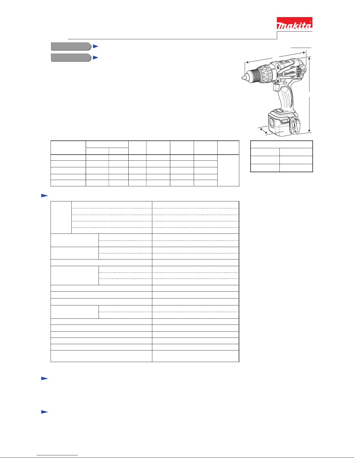
Model BHP448 is a successor model of BHP444, featuring:
• Extremely compact tool size with an overall length of 225mm (8-7/8") -
the shortest in its class
• High power and productivity achieved with new DC motor (FD31-30)
• Enhanced dust and drip-proof performance to ensure reliable operation
even under bad weather.
• Equipped with Battery fuel gauge for increased maneuverability.
This product is available in the following variations.
PRODUCT
Housing
color
BHP448RFE DC18RC
Model No.
Type
Quantity
Charger
Plastic
carrying
case
Battery
cover
Yes2
Battery
BL1430 1
No NoNoNo NoBHP448Z
Makita
blue
BHP448RFE3 DC18RC Yes
Systainer
case
No
No
BHP448RFX DC18RC No2BL1430 1
Yes
No NoNoNo NoBHP448ZX Yes
No3BL1430 2
Battery
Capacity of drill chuck: mm (")
Capacity: mm (")
Max lock torque: N.m (in.lbs)
Electric brake
Variable speed control
Mechanical speed control
Reversing switch
Max fastening
torque: N.m (in.lbs)
Torque setting
Steel
Wood
Soft joint
Hard joint
No load speed:
min
ˉ¹=rpm
Energy capacity: Wh
Voltage: V
Capacity: Ah
High
Weight according to
EPTA-Procedure 01/2003*4: kg (lbs)
Low
44
Cell Li-ion
Charging time (approx.): min.
22 with DC18RC (DC18RA*3)
14.4
3.0
Yes
Yes
Yes (2 speeds)
Yes
Yes
2.2 (4.9)
13 (1/2)
65 (2-9/16)
21 stage + drill mode
Clutch torque setting: N.m (in.lbs)
1.0 - 10.0 (9 - 89)
67 (590)
43 (380)
77 (680)
0 - 1,800
0 - 350
1.5 (1/16) - 13 (1/2)
LED job light
T
ECHNICAL INFORMATION
Dimensions: mm (")
Width (W)
Height (H)
Length (L)
225 (8-7/8)
79 (3-1/8)
259 (10-1/4)
Note: This product is not compatible with 14.4V-1.3Ah battery BL1415.
Depth rod ................... 1
Masonry 14 (9/16)
Impacts per minute:
min
ˉ¹=ipm
High
Low
0 - 27,000
0 - 5,200
* with Battery BL1430
W
L
H
[3] DISASSEMBLY/ASSEMBLY
[3] -1. Drill Chuck
CAUTION: Repair the machine in accordance with “Instruction manual” or “Safety instructions”.
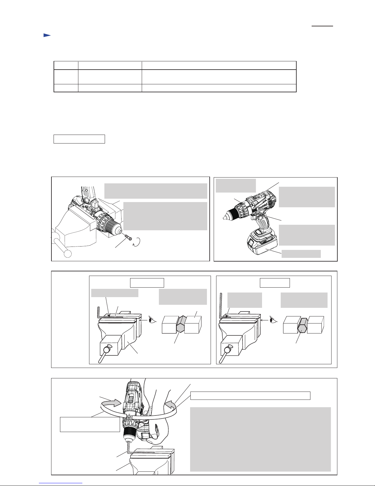
DISASSEMBLING
Fig. 1
M6x22 Flat head screw (Left handed thread)
(1) Remove M6x22 Flat head screw as drawn in Fig. 1.
(2) Preset the machine as drawn in Fig. 2. And set Hex wrench 10 to Vise as drawn in Fig. 3.
(3) Gripping Hex wrench 10 with Drill chuck firmly, remove Drill chuck as drawn in Fig. 4.
Fig. 2
Attach Battery.
F/R change lever
Set F/R Change lever
to Reverse (counter-
clockwise) rotation.
Set Speed change lever
to Low speed mode
designated with 1.
Speed change lever
Set Change ring
to Drill mode.
Change ring
P 2/ 12
Repair
It is not required to lubricate the gear section because the portion is replaced as a factory-assembled gear unit.
[1] NECESSARY REPAIRING TOOLS
[2] LUBRICATION
Code No. Description Use for
1R359 Drill chuck removing tool
Hex wrench 10
(Use this tool if Drill chuck cannot be removed by the method of
described in “[3]-1 Drill chuck disassembling”.)
removing/ mounting Drill chuck
Open Drill chuck fully and remove M6x22
Flat head screw by turning it clockwise.
CORRECT WRONG
Fig. 3
Fig. 4
Setting of
Hex wrench
10
Vise
Grip flat surfaces
of Hex wrench 10.
Hex wrench 10
Hex wrench 10,
viewed from side [A]
Vise
Hold the long end.
[A]
Do not hold edges
of Hex wrench 10.
Do not hold
the short end.
Hex wrench 10,
viewed from side [A]
Note: Use Impact driver to unscrew
M6x22 Flat head screw if it
could not be removed
manually.
[A]
Clockwise
Counterclockwise
Hex wrench 10
Vise
Clockwise* recoil force
of Machine
*Note: The rotational direction is viewed from operator.
1. Hold Hex wrench 10 with Drill chuck and grip Machine.
Important:
Grip Machine tightly with both hands to provide
the sufficient counterclockwise* force against clockwise*
recoil force of Machine.
2. Pull Switch trigger slowly.
3. Spindle rotates counterclockwise* and consequently
Drill chuck is removed from spindle.
Counterclockwise* force to be applied by operator
[3] DISASSEMBLY/ASSEMBLY
[3] -1. Drill Chuck (cont.)
P 3/ 12
Repair
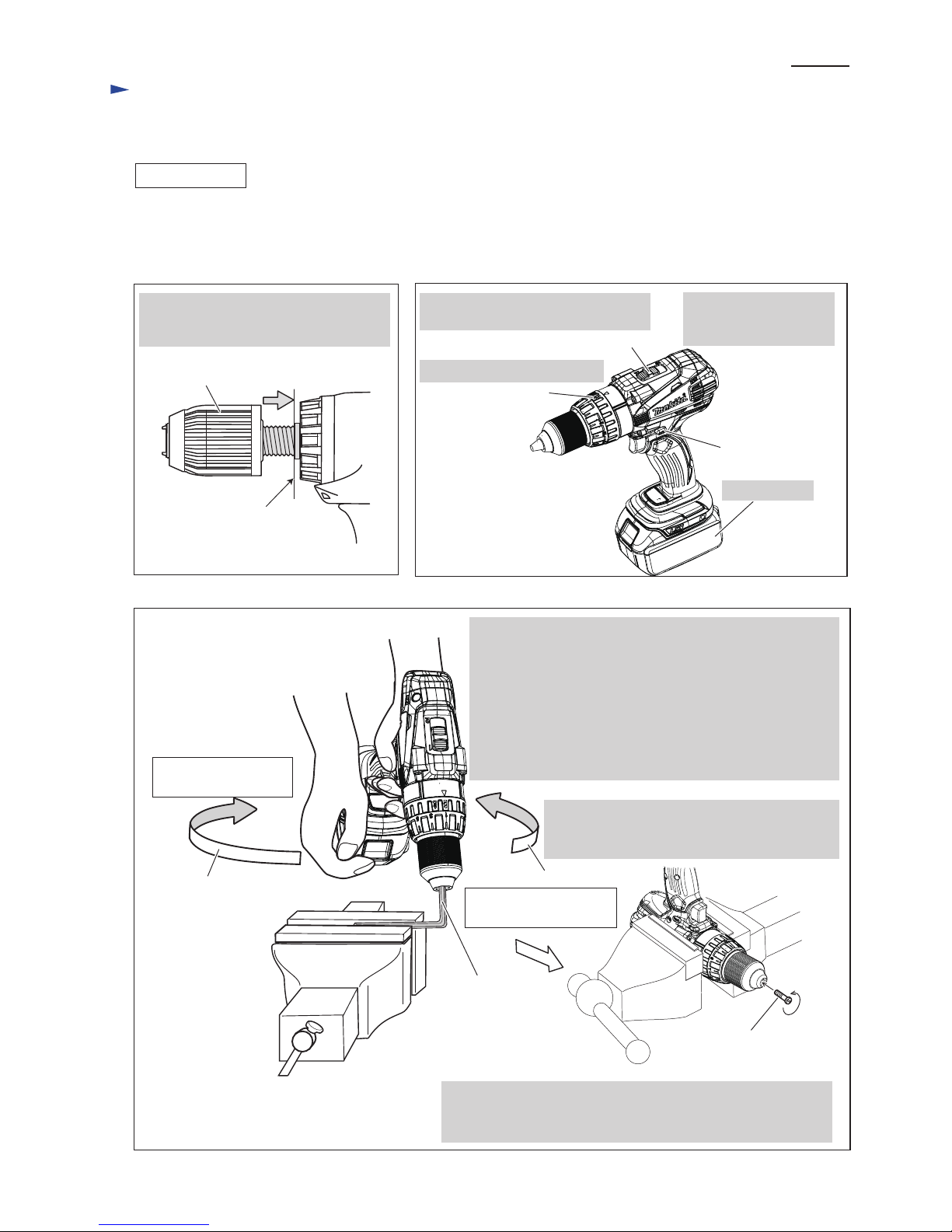
ASSEMBLING
Fig. 5
End of the threaded
portion of Spindle
Drill chuck
Fig. 6
Attach Battery.
F/R change lever
Set F/R Change lever
to Forward (clockwise)
rotation.
Set Speed change lever to Low speed
mode designated with 1.
Speed change lever
Set Change ring to Drill mode.
Change ring
Counterclockwise
Hex wrench 10
Fig. 7
Clockwise
4. Open Drill chuck fully, and tighten Drill chuck
with M6x22 Flat head screw by turning it
counterclockwise with Impact driver.
(1) Set the machine. (Fig. 5 and 6)
(2) Set Hex wrench 10 to vise and described in Fig. 3.
(3) Set Drill chuck in place. (Fig. 7)
M6x22 Flat head screw
(Left handed thread)
Turn Drill chuck clockwise by hand until
it sits on the end of the threaded portion
of Spindle.
Note: Apply adhesive (ThreeBond 1321B/1342 or Loctite 242)
to threaded portion when re-using the removed M6x22
Flat head screw.
Counterclockwise recoil
force of Machine
*Note: The rotational direction is viewed from operator.
1. Hold Hex wrench 10 with Drill chuck and grip Machine.
Important: Grip Machine hard with both hands to provide
sufficient clockwise* force against
counterclockwise* recoil force of Machine.
2. Pull Switch trigger slowly to turn Spindle clockwise*.
Note: Pull the Trigger so that Spindle’s rotating reaches full
speed in one second.
3. Drill chuck is tightened and consequently Spindle is locked.
Clockwise* force to be
applied by operator
P 4/ 12
Repair
[3] DISASSEMBLY/ASSEMBLY
[3] -2. Gear Assembly, Motor Section
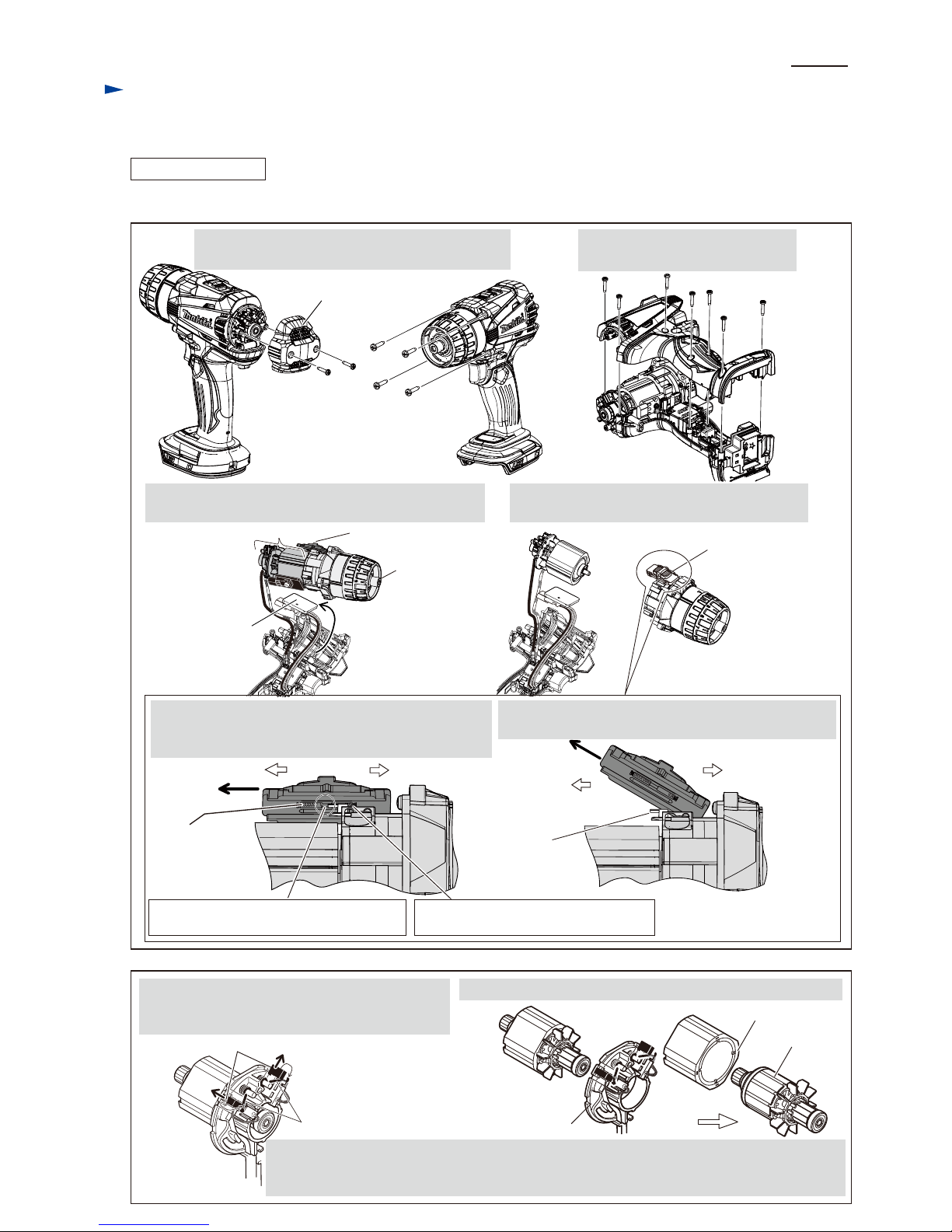
DISASSEMBLING
Fig. 8
1. Remove two 3x16 Tapping screws and Rear cover.
And remove four 4x18 Tapping screws.
After removing Drill chuck (Re: Figs. 1, 2, 3 and 4), disassemble Motor section and Gear assembly. (Figs. 8 and 9)
2. Remove Housing R, unscrewing
seven 3x16 Tapping screws.
3. Pull out Heat sink section, and remove Gear assembly
together with Motor section and Speed change lever.
4. Remove Speed change lever and Motor section
from Gear assembly.
Gear assembly
Speed change leverMotor section
Motor section
Rear cover
3x16 Tapping
screw (2 pcs.)
4x18 Tapping
screw (4 pcs.)
3x16 Tapping screw (7 pcs.)
Heat sink
section
Speed change
lever assembly
rear
Compression
spring 4
front Compression spring 4 compressed
by the lever of Gear assembly
Drill chuck sideMotor side Drill chuck side
Motor side
5. Push Speed change lever assembly toward Motor side
until it stops to have space between the pin on the lever
of Gear assembly and rear Compression spring 4.
6. Lifting up Motor side of Speed change lever assembly,
pull it toward the direction designated with arrow.
Space between rear Compression spring 4
and the pin on the lever of Gear assembly.
Pin on
the lever of
Gear assembly
Fig. 9
Torsion spring
Carbon brush
Brush holder complete
Yoke unit
Armature
Note: Pay attention not to pinch your finger between Yoke unit and Armature when removing.
Do not scratch the copper wires of Armature. Yoke unit draws Armature by its considerable
strong magnet force.
5. Shift the tail of Torsion spring from top of Carbon
brush to the Notch of Brush holder. Carbon brush
gets free from the pressure of Torsion spring.
6. From Armature, pull off Brush holder complete and Yoke unit.
 Loading...