

Page 1
GB
Cordless Driver Drill Instruction Manual
F
Perceuse-visseuse sans fil Manuel d’instructions
D
Akku-bohrschrauber Betriebsanleitung
I
Trapano-avvitatore a batteria Istruzioni per l’uso
NL
Snoerloze boor-schroevedraaier Gebruiksaanwijzing
E
Taladro-atornillador a batería Manual de instrucciones
P
Berbequim aparafusador a bateria Manual de instruções
DK
Akku bore-skruemaskine Brugsanvisning
S
Sladdlös borrmaskin/skruvdragare Bruksanvisning
N
Akku boreskrutrekker Bruksanvisning
SF
Akkuporakone Käyttöohje
GR Βιδοτρύπανο µε µπαταρία Οδηγίες χρήσεως
6204D
Page 2
1
2
2
3
4
12
6
5
7
8
34
9
10
12
11
13
9
14
15
16
56
18
17
19
20
78
2
Page 3
22
23
21
910
3
Page 4

ENGLISH
1Button
2 Battery cartridge
3 Charging light
4 Fast charger
5 Tighten
6Sleeve
7 Ring
8 Switch trigger
Explanation of general view
9 Reversing switch lever
10 A side
11 B side
12 Clockwise
13 Counterclockwise
14 Low speed
15 High speed
16 Speed change lever
17 Adjusting ring
18 Graduations
19 Drill marking
20 Pointer
21 Limit mark
22 Screwdriver
23 Brush holder cap
SPECIFICATIONS
Model 6204D
Capacities
Steel .................................................................. 10 mm
Wood ................................................................. 21 mm
Wood screw ....................................... 6.1 mm x 55 mm
Tool screw ........................................................... 6 mm
No load speed (min
High ............................................................... 0 – 1,100
Low ................................................................... 0 – 350
Overall length ..................................................... 197 mm
Net weight ............................................................. 1.5 kg
Rated voltage ................................................... D.C.9.6 V
• Due to our continuing program of research and devel-
opment, the specifications herein are subject to change
without notice.
• Note: Specifications may differ from country to country.
Safety hints
For your own safety, please refer to the enclosed safety
instructions.
–1
)
IMPORTANT SAFETY INSTRUCTIONS FOR
CHARGER & BATTERY CARTRIDGE
1. SAVE THESE INSTRUCTIONS — This manual
contains important safety and operating instructions for battery charger.
2. Before using battery charger, read all instruc-
tions and cautionary markings on (1) battery
charger, (2) battery, and (3) product using battery.
3. CAUTION — To reduce risk of injury, charge only
MAKITA type rechargeable batteries. Other types
of batteries may burst causing personal injury
and damage.
4. Do not expose charger to rain or snow.
5. Use of an attachment not recommended or sold
by the battery charger manufacturer may result
in a risk of fire, electric shock, or injury to persons.
6. To reduce risk of damage to electric plug and
cord, pull by plug rather than cord when disconnecting charger.
7. Make sure cord is located so that it will not be
stepped on, tripped over, or otherwise subjected
to damage or stress.
8. Do not operate charger with damaged cord or
plug — replace them immediately.
9. Do not operate charger if it has received a sharp
blow, been dropped, or otherwise damaged in
any way; take it to a qualified serviceman.
ENC001-3
10. Do not disassemble charger or battery cartridge;
take it to a qualified serviceman when service or
repair is required. Incorrect reassembly may
result in a risk of electric shock or fire.
11. To reduce risk of electric shock, unplug charger
from outlet before attempting any maintenance
or cleaning. Turning off controls will not reduce
this risk.
12. The battery charger is not intended for use by
young children or infirm persons without supervision.
13. Young children should be supervised to ensure
that they do not play with the battery charger.
14. If operating time has become excessively
shorter, stop operating immediately. It may result
in a risk of overheating, possible burns and even
an explosion.
15. If electrolyte gets into your eyes, rinse them out
with clear water and seek medical attention right
away. It may result in loss of your eyesight.
ADDITIONAL SAFETY RULES FOR CHARGER
& BATTERY CARTRIDGE
1. Do not charge Battery Cartridge when temperature is BELOW 10°C (50°F) or ABOVE 40°C
(104°F).
2. Do not attempt to use a step-up transformer, an
engine generator or DC power receptacle.
3. Do not allow anything to cover or clog the
charger vents.
4. Always cover the battery terminals with the battery cover when the battery cartridge is not
used.
5. Do not short the battery cartridge:
(1) Do not touch the terminals with any conduc-
tive material.
(2) Avoid storing battery cartridge in a container
with other metal objects such as nails, coins,
etc.
(3) Do not expose battery cartridge to water or
rain.
A battery short can cause a large current flow,
overheating, possible burns and even a breakdown.
6. Do not store the tool and battery cartridge in
locations where the temperature may reach or
exceed 50°C (122°F).
7. Do not incinerate the battery cartridge even if it
is severely damaged or is completely worn out.
The battery cartridge can explode in a fire.
8. Be careful not to drop, shake or strike battery.
4
Page 5

9. Do not charge inside a box or container of any
kind. The battery must be placed in a well ventilated area during charging.
ADDITIONAL SAFETY RULES FOR TOOL
1. Be aware that this tool is always in an operating
condition, because it does not have to be
plugged into an electrical outlet.
2. Hold tool by insulated gripping surfaces when
performing an operation where the cutting tool
may contact hidden wiring. Contact with a “live”
wire will also make exposed metal parts of the
tool “live” and shock the operator.
3. Always be sure you have a firm footing.
4. Be sure no one is below when using the tool in
high locations.
5. Hole the tool firmly.
6. Keep hands away from rotating parts.
7. Do not leave the tool running. Operate the tool
only when hand-held.
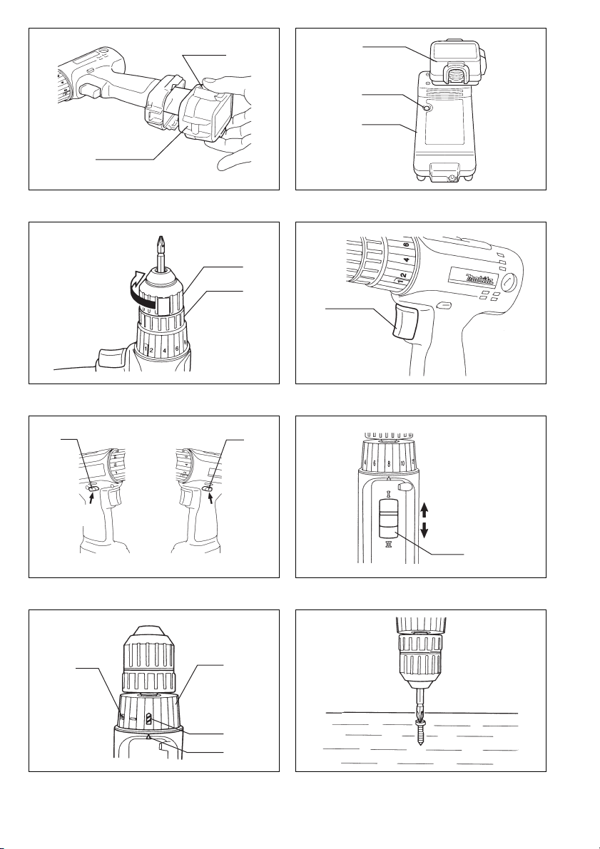
Charging (Fig. 2)
Plug the battery charger into the proper A/C voltage source. The charging light will flash in green color. Insert the battery cartridge so that the plus and minus terminals on the battery cartridge are on the same sides as their respective
markings on the battery charger. Insert the cartridge fully into the port so that it rests on the charger port floor. When
the battery cartridge is inserted, the charging light color will change from green to red and charging will begin. The
charging light will remain lit steadily during charging. When the charging light color changes from red to green, the
charging cycle is complete. The charging time is approximately one hour. If you leave the battery cartridge in the
charger after the charging cycle is complete, the charger will switch into its “trickle charge (maintenance charge)”
mode. After charging, unplug the charger from the power source. Refer to the table below for the charging time.
Battery type Capacity (Ah) Number of cells Charging time
9100 (Ni-cd) 1.3 8 Approx. 30 min.
9102 (Ni-cd) 2.0 8 Approx. 45 min.
9102A (Ni-cd) 2.0 8 Approx.45 min.
9122 (Ni-cd) 2.0 8 Approx. 45 min.
9133 (Ni-MH) 2.2 8 Approx. 50 min.
9134 (Ni-MH) 2.6 8 Approx. 60min.
9135 (Ni-MH) 3.0 8 Approx. 70min.
CAUTION:
• The fast charger is for charging Makita bettery cartrige. Never use it for other purposes or for other manufactor’s bat-
teries.
• When you charge a new battery cartridge or a battery cartridge which has not been used for a long period of time, it
may not accept a full charge. This is a normal condition and does not indicate a problem. You can recharge the battery cartridge fully after discharging it completely and recharging a couple of times.
• If you charge a battery cartridge from a just-operated tool or a battery cartridge which has been left in a location
exposed to direct sunlight or heat for a long time, the charging light may flash in red color. If this occurs, wait for a
while. Charging will begin after the battery cartridge cools. The battery cartridge will cool faster if you remove the
battery cartridge from the fast charger.
• If the charging light flashes alternately in green and red color, a problem exists and charging is not possible. The ter-
minals on the charger or battery cartridge are clogged with dust or the battery cartridge is worn out or damaged.
• If you wish to charge two battery cartridges, allow 15 minutes between chargings on the fast charger.
Trickle charge (Maintenance charge)
If you leave the battery cartridge in the charger to prevent spontaneous discharging after full charge, the charger will
switch into its “trickle charge (maintenance charge)” mode and keep the battery cartridge fresh and fully charged.
ENB022-1
8. Do not touch the drill bit or the workpiece immediately after operation; they may be extremely
hot and could burn your skin.
SAVE THESE INSTRUCTIONS.
OPERATING INSTRUCTIONS
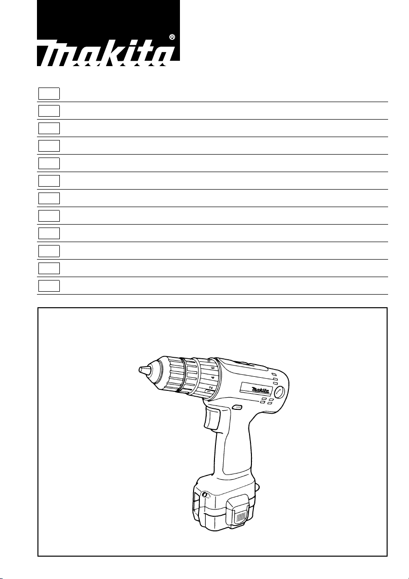
Installing or removing battery cartridge (Fig. 1)
• Always switch off the tool before insertion or removal of
the battery cartridge.
• To remove the battery cartridge, withdraw it from the
tool while pressing the buttons on both sides of the cartridge.
• To insert the battery cartridge, align the tongue on the
battery cartridge with the groove in the housing and slip
it into place. Always insert it all the way until it locks in
place with a little click. If not, it may accidentally fall out
of the tool, causing injury to you or someone around
you.
• Do not use force when inserting the battery cartridge. If
the cartridge does not slide in easily, it is not being
inserted correctly.
5
Page 6
Tips for maintaining maximum battery life
1. Charge the battery cartridge before completely discharged. Always stop tool operation and charge the battery
cartridge when you notice less tool power.
2. Never recharge a fully charged battery cartridge. Overcharging shortens the battery service life.
3. Charge the battery cartridge with room temperature at 10°C – 40°C (50°F – 104°F).
Let a hot battery cartridge cool down before charging it.
4. Charge the Nickel Metal Hydride battery cartridge when you do not use it for more than six months.
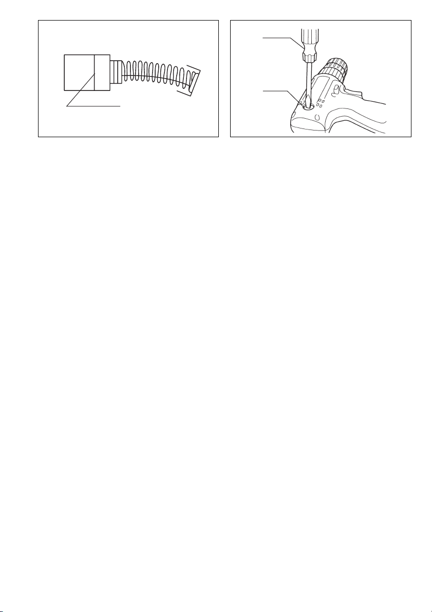
Installing or removing driver bit or drill bit (Fig. 3)
Important:
Always be sure that the tool is switched off and the battery cartridge is removed before installing or removing
the bit.
Hold the ring and turn the sleeve counterclockwise to
open the chuck jaws. Place the bit in the chuck as far as it
will go. Hold the ring firmly and turn the sleeve clockwise
to tighten the chuck.
To remove the bit, hold the ring and turn the sleeve counterclockwise.
Switch action (Fig. 4)
CAUTION:
Before inserting the battery cartridge into the tool, always
check to see that the switch trigger actuates properly and
returns to the “OFF” position when released.
To start the tool, simply pull the trigger. Tool speed is
increased by increasing pressure on the trigger. Release
the trigger to stop.
Reversing switch action (Fig. 5)
CAUTION:
• Always check the direction of rotation before operation.
• Use the reversing switch only after the tool comes to a
complete stop. Changing the direction of rotation
before the tool stops may damage the tool.
• When not operating the tool, always set the reversing
switch lever to the neutral position.
This tool has a reversing switch to change the direction of
rotation. Depress the reversing switch lever from the A
side for clockwise rotation or from the B side for counterclockwise rotation. When the switch lever is in the neutral
position, the switch trigger cannot be pulled.
Speed change (Fig. 6)
To change the speed, first switch off the tool and then
slide the speed change lever to the “ II ” side for high
speed or “ I ” side for low speed. Be sure that the speed
change lever is set to the correct position before operation. Use the right speed for your job.
CAUTION:
• Always set the speed change lever fully to the correct
position. If you operate the tool with the speed change
lever positioned half-way between the “ I ” side and “ II ”
side, the tool may be damaged.
• Do not use the speed change lever while the tool is run-
ning. The tool may be damaged.
Adjusting the fastening torque (Fig. 7)
The fastening torque can be adjusted in 17 steps by turning the adjusting ring so that its graduations are aligned
with the pointer on the tool body. The fastening torque is
minimum when the number 1 is aligned with the pointer,
and maximum when the marking A is aligned with the
pointer.
The clutch will slip at various torque levels when set at
the number 1 to 16. The clutch is designed not to slip at
the A marking. Before actual operation, drive a trial
screw into your material or a piece of duplicate material
to determine which torque level is required for a particular application.
NOTE:
Do not operate the tool with the adjusting ring set
between the number 16 and the A marking. The tool may
be damaged.
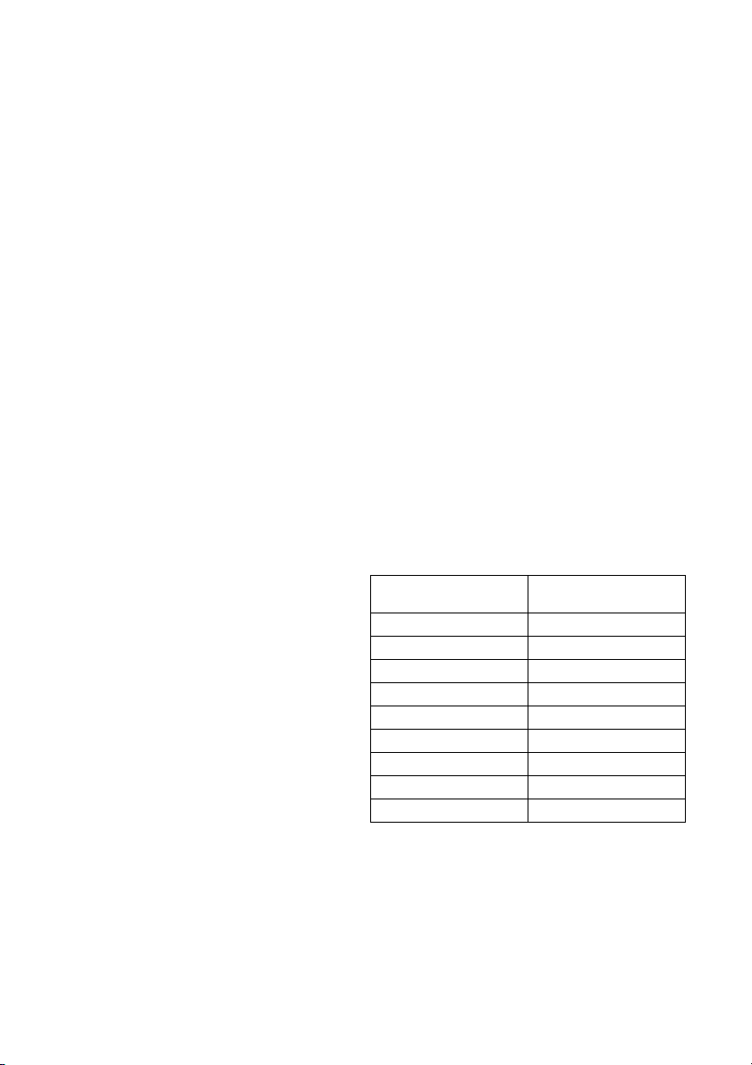
Screwdriving operation (Fig. 8)
Place the point of the driver bit in the screw head and
apply pressure to the tool. Start the tool slowly and then
increase the speed gradually. Release the trigger as
soon as the clutch cuts in.
NOTE:
• Make sure that the driver bit is inserted straight in the
screw head, or the screw and/or bit may be damaged.
• When driving wood screws, predrill pilot holes to make
driving easier and to prevent splitting of the workpiece.
See the chart below.
Nominal diameter of
wood screw (mm)
3.1 2.0 – 2.2
3.5 2.2 – 2.5
3.8 2.5 – 2.8
4.5 2.9 – 3.2
4.8 3.1 – 3.4
5.1 3.3 – 3.6
5.5 3.6 – 3.9
5.8 4.0 – 4.2
6.1 4.2 – 4.4
• If the tool is operated continuously until the battery cartridge has discharged, allow the tool to rest for 15 minutes before proceeding with a fresh battery.
Recommended size of
pilot hole (mm)
6
Page 7

Drilling operation
First, turn the adjusting ring so that the pointer on the tool
body points to the A marking. Then proceed as follows.
• Drilling in wood
When drilling in wood, best results are obtained with
wood drills equipped with a guide screw. The guide
screw makes drilling easier by pulling the bit into the
workpiece.
• Drilling in metal
To prevent the bit from slipping when starting a hole,
make an indentation with a centerpunch and hammer
at the point to be drilled. Place the point of the bit in the
indentation and start drilling. Use a cutting lubricant
when drilling metals. The exceptions are iron and brass
which should be drilled dry.
CAUTION:
• Pressing excessively on the tool will not speed up the
drilling. In fact, this excessive pressure will only serve
to damage the tip of your bit, decrease the tool performance and shorten the service life of the tool.
• There is a tremendous force exerted on the tool/bit at
the time of hole breakthrough. Hold the tool firmly and
exert care when the bit begins to break through the
workpiece.
• A stuck bit can be removed simply by setting the
reversing switch to reverse rotation in order to back out.
However, the tool may back out abruptly if you do not
hold it firmly.
• Always secure small workpieces in a vise or similar
hold-down device.
• If the tool is operated continuously until the battery cartridge has discharged, allow the tool to rest for 15 minutes before proceeding with a fresh battery.
MAINTENANCE
CAUTION:
Always be sure that the tool is switched off and the battery cartridge is removed before carrying out any work on
the tool.
Replacement of carbon brushes (Fig. 9 & 10)
Replace carbon brushes when they are worn down to the
limit mark. Both identical carbon brushes should be
replaced at the same time.
To maintain product safety and reliability, repairs, maintenance or adjustment should be carried out by a Makita
Authorized Service Center.
ACCESSORIES
CAUTION:
• These accessories or attachments are recommended
for use with your Makita tool specified in this manual.
The use of any other accessories or attachments might
present a risk of injury to persons. Only use accessory
or attachment for its stated purpose.
If you need any assistance for more details regarding
these accessories, ask your local Makita service center.
•Screw bits
• Rubber pad assembly
• Foam polishing pad 125
• Wool bonnet 100
• Various type of Makita genuine batteries and chargers
• Plastic carrying case
7
Page 8

NEDERLANDS
1 Knop
2 Accu
3 Oplaadlampje
4 Snellader
5 Vastdraaien
6Bus
7 Ring
8 Trekschakelaar
Verklaring van algemene gegevens
9 Omkeerschakelaar
10 Zijde A
11 Zijde B
12 Rechtse draairichting
13 Linkse draairichting
14 Laag toerental
15 Hoog toerental
16 Toerentalschakelaar
17 Stelring
18 Schaalverdelingen
19 Boormarkering
20 Wijzer
21 Limietaanduiding
22 Schroevendraaier
23 Dop van koolborstelhouder
TECHNISCHE GEGEVENS
Model 6204D
Capaciteiten
Staal ..................................................................10 mm
Hout ...................................................................21 mm
Houtschroef ....................................... 6,1 mm x 55 mm
Kolomschroef ....................................................... 6 mm
Toerental onbelast (min
Hoog .............................................................. 0 – 1 100
Laag ..................................................................0 – 350
Totale lengte .......................................................197 mm
Netto gewicht ......................................................... 1,5 kg
Nominale spanning ..........................................D.C. 9,6 V
• In verband met ononderbroken research en ontwikke-
ling behouden wij ons het recht voor bovenstaande
technische gegevens te wijzigen zonder voorafgaande
kennisgeving.
• Opmerking: De technische gegevens kunnen van land
tot land verschillen.
Veiligheidswenken
Voor uw veiligheid dient u de bijgevoegde Veiligheidsvoorschriften nauwkeurig op te volgen.
–1
)
BELANGRIJKE
VEILIGHEIDSVOORSCHRIFTEN VOOR
GEBRUIK VAN DE BATTERIJLADER EN HET
BATTERIJPAK
1. BEWAAR DEZE VOORSCHRIFTEN — In deze
gebruiksaanwijzing staan belangrijke veiligheids- en bedieningsvoorschriften betreffende
de batterijlader (snellader).
2. Lees alle voorschriften en waarschuwingen
betreffende (1) de batterijlader, (2) het batterijpak
en (3) het gereedschap aandachtig door alvorens de batterijlader in gebruik te nemen.
3. LET OP — Om het gevaar voor ongelukken te
verminderen, dient u met de snellader uitsluitend MAKITA oplaadbare batterijen te laden. Batterijen van andere merken kunnen gaan barsten
en hierdoor verwondingen of schade veroorzaken.
4. Stel de batterijlader niet bloot aan regen of
sneeuw.
5. Het gebruik van accessoires die niet door de
fabrikant van de batterijlader worden verkocht of
aanbevolen, kan brandgevaar, elektrische schok
of verwondingen veroorzaken.
6. Om de stekker en het netsnoer niet te beschadi-
gen, trekt u het netsnoer uit het stopkontakt
door de stekker vast te pakken.
7. Let op dat het snoer zodanig op de grond ligt,
dat niemand erop kan stappen of erover kan
struikelen en dat er niets op het snoer geplaatst
wordt.
8. Gebruik in geen geval de batterijlader als het
netsnoer of de stekker beschadigd is. Vervang
deze onmiddellijk.
9. Gebruik de batterijlader ook niet als deze gevallen is, aan een zware stoot heeft blootgestaan, of
als u vermoedt dat hij beschadigd is. Laat in
deze gevallen de batterijlader eerst nakijken.
10. Haal de batterijlader of het batterijpak niet uit
elkaar; laat eventuele servicebeurten of reparaties uitsluitend vakkundig uitvoeren. Het onjuist
opnieuw in elkaar zetten kan namelijk elektrische schok of brandgevaar opleveren.
11. Om gevaar voor elektrische schok te verminderen, trekt u de stekker uit het stopkontakt alvorens de batterijlader te reinigen of een
onderhoudsbeurt te geven. Door de batterijlader
alleen maar uit te schakelen, vermindert u dit
gevaar niet.
12. De acculader is niet bedoeld voor gebruik door
kleine kinderen of geestelijk gestoorden waarop
geen toezicht wordt gehouden.
13. Houd toezicht op kleine kinderen om te voorkomen dat ze met de acculader spelen.
14. Als de gebruiksduur van de accu bijzonder kort
geworden is, moet u het gebruik ervan onmiddellijk stopzetten omdat er anders gevaar is voor
oververhitting, brandwonden en zelfs een explosie.
15. Als er elektrolyt in uw ogen is terechtgekomen,
moet u deze spoelen met schoon water en
onmiddellijk de hulp van een dokter inroepen.
Elektrolyt in de ogen kan blindheid veroorzaken.
BIJGEVOEGDE
VEILIGHEIDSVOORSCHRIFTEN VOOR
GEBRUIK VAN DE BATTERIJLADER EN HET
BATTERIJPAK
1. Laad het batterijpak niet op als de temperatuur
LAGER is dan 10°C of HOGER dan 40°C.
2. Gebruik voor het laden nooit een step-up transformator, een dynamo of een gelijkstroombron.
3. Zorg dat de ventilatiegaten van de batterijlader
niet afgesloten worden of verstopt raken.
4. Bedek altijd de polen van de accu met het accudeksel wanneer u de accu niet gebruikt.
21
Page 9

5. Voorkom kortsluiting van het batterijpak:
(1) Raak de aansluitklemmen nooit aan met
geleidend materiaal.
(2) Bewaar het batterijpak niet op een plaats
waar ook andere metalen voorwerpen zoals
spijkers, munten e.d. worden bewaard.
(3) Stel het batterijpak niet bloot aan water of
regen.
Kortsluiting van het batterijpak kan leiden tot
een grote stroomafgifte, oververhitting, brandwonden of zelfs tot defecten.
6. Bewaar de batterijlader en het batterijpak niet in
plaatsen waar de temperatuur tot 50°C of hoger
kan op lopen.
7. Werp zwaar beschadigde of volledig uitgeputte
batterijpakken niet in het vuur, omdat een
gevaarlijke explosie er het gevolg van kan zijn.
8. Wees voorzichtig dat u het batterijpak niet laat
vallen en het niet aan schokken of stoten blootstelt.
9. Laad het batterijpak niet op in een kist, een container e.d. Om het batterijpak op te laden, dient u
dit in een goed geventileerde ruimte te plaatsen.
AANVULLENDE VEILIGHEIDSVOORSCHRIFT
EN VOOR HET GEREEDSCHAP
1. Denk eraan dat dit gereedschap altijd gebruiksklaar is, aangezien het niet hoeft te worden aangesloten op een stopcontact.
2. Houd het gereedschap bij de geïsoleerde handgrepen vast wanneer u boort op plaatsen waar
de boor op verborgen elektrische bedrading kan
stoten. Door contact met een onder spanning
staande draad zullen ook de niet-geïsoleerde
metalen delen van het gereedschap onder spanning komen te staan, zodat de gebruiker een
elektrische schok kan krijgen.
3. Zorg ervoor dat u altijd stevige steun voor de
voeten hebt.
4. Controleer of er zich niemand onder u bevindt
wanneer u het gereedschap op een hoge plaats
gaat gebruiken.
5. Houd het gereedschap stevig vast.
6. Houd uw handen uit de buurt van roterende
onderdelen.
7. Laat het gereedschap niet achter terwijl het nog
in bedrijf is. Laat het gereedschap alleen draaien
wanneer u het met beide handen vasthoudt.
8. Raak de boor of het werkstuk niet aan onmiddellijk na het gebruik; deze kunnen zeer heet zijn en
brandwonden veroorzaken.
BEWAAR DEZE VOORSCHRIFTEN.
BEDIENINGSVOORSCHRIFTEN
Installeren of verwijderen van de accu (Fig. 1)
• Schakel het gereedschap altijd uit alvorens de accu te
installeren of te verwijderen.
• Om de accu te verwijderen, neemt u deze uit het
gereedschap terwijl u de knoppen aan beide zijden van
de accu indrukt.
• Om de accu te installeren, past u de rug op de accu in
de groef in de behuizing van het gereedschap, en dan
schuift u de accu naar binnen. Schuif de accu zo ver
mogelijk erin, totdat deze met een klikgeluid vergrendelt. Indien u dit niet doet, kan de accu per ongeluk uit
het gereedschap vallen en uzelf of anderen verwonden.
• Als de accu moeilijk in de houder gaat, moet u niet pro-
beren hem met geweld erin te duwen. Indien de accu
er niet gemakkelijk ingaat, betekent dit dat u hem niet
op de juiste wijze erin steekt.
Laden (Fig. 2)
Sluit de acculader aan op een stopkontakt. Het laadcontrolelampje zal in groen knipperen. Schuif de accu zodanig in
de acculader dat de plus en min klemmen van de accu overeenkomen met de plus en min markeringen op de acculader. Schuif de accu zo ver mogelijk in de opening, zodat het op de bodem van de lader rust. Wanneer de accu helemaal erin zit, zal de kleur van het laadcontrolelampje veranderen van groen in rood en zal het laden beginnen. Tijdens
het laden zal het laadcontrolelampje blijven branden. Wanneer de kleur van het oplaadlampje verandert van rood in
groen, is het opladen voltooid. De oplaadtijd is ongeveer een uur. Wanneer u een volledig opgeladen accu in de lader
laat zitten, zal de lader overschakelen naar de “bijladen (handhaven van de lading)” stand. Trek de stekker van de
lader uit het stopkontakt nadat het laden is voltooid. Zie de onderstaande tabel voor de oplaadtijden.
Accu type Capaciteit (Ah) Aantal cellen Oplaadtijd
9100 (Ni-cd) 1,3 8 ca. 30 min.
9102 (Ni-cd) 2,0 8 ca. 45 min.
9102A (Ni-cd) 2,0 8 ca.45 min.
9122 (Ni-cd) 2,0 8 ca. 45 min.
9133 (Ni-MH) 2,2 8 ca. 50min.
9134 (Ni-MH) 2,6 8 ca. 60min.
9135 (Ni-MH) 3,0 8 ca. 70min.
22
Page 10

LET OP:
• De snellader is uitsluitend bestemd voor het laden van Makita accu’s. Gebruik deze nooit voor andere doeleinden of
voor het laden van accu’s van andere fabrikanten.
• Een nieuwe accu of een accu die gedurende lange tijd niet werd gebruikt, kan eventueel niet volledig worden geladen. Dit is normaal en duidt niet op een defect. Nadat de accu een paar keer volledig is ontladen en herladen, kunt u
deze weer volledig laden.
• Wanneer u de accu van een zojuist gebruikt gereedschap laadt, of een accu die voor langere tijd aan direct zonlicht
of hitte werd blootgesteld, gebeurt het wel eens dat het oplaadlampje in rood knippert. Wacht in zo’n geval een tijdje.
Het laden zal beginnen nadat de accu is afgekoeld. De accu zal sneller afkoelen indien u deze van de snellader verwijdert.
• Indien het oplaadlampje afwisselend in groen en rood knippert, wijst dit op een probleem en is laden niet mogelijk.
De klemmen op de snellader of op de accu zijn vuil of de accu is versleten of beschadigd.
• Als u twee accu’s achtereen wilt laden, geef dan de snellader tussendoor 15 minuten rust.
Bijladen (Handhaven van de lading)
Wanneer u een volledig opgeladen accu in de lader laat zitten om spontaan ontladen te voorkomen, zal de lader overschakelen naar de “Bijladen (Handhaven van de lading)” stand waardoor de accu vers en in volledig opgeladen toestand wordt gehouden.
Wenken om een maximale levensduur van de accu te handhaven
1. Laad de accu op alvorens deze volledig is ontladen.
Stop het gebruik van het gereedschap en laad de accu op telkens wanneer u vaststelt dat het vermogen van het
gereedschap verminderd is.
2. Laad een volledig opgeladen accu nooit opnieuw op.
Wanneer u de accu te veel oplaadt, zal deze minder lang meegaan.
3. Laad de accu op bij een kamertemperatuur tussen 10°C en 40°C.
Laat een warme accu afkoelen alvorens deze op te laden.
4. Laad de nikkel-metaalhydride accu op wanneer u deze langer dan zes maanden niet gebruikt.
Installeren of verwijderen van de schroefbit of
boor (Fig. 3)
Belangrijk:
Controleer altijd of het gereedschap is uitgeschakeld en
de accu is verwijderd alvorens de boor te installeren of te
verwijderen.
Houd de ring vast en draai de bus naar links om de klauwen van de boorkop te openen. Steek de boor zo ver
mogelijk in de boorkop. Houd daarna de ring weer stevig
vast en draai de bus naar rechts om de boorkop vast te
zetten.
Om de boor te verwijderen, houdt u de ring vast en draait
u de bus naar links.
Werking van de trekschakelaar (Fig. 4)
LET OP:
Alvorens de accu in het gereedschap te plaatsen, moet u
altijd controleren of de trekschakelaar juist werkt en bij
het loslaten naar de “OFF” positie terugkeert.
Om het gereedschap in te schakelen, drukt u gewoon de
trekschakelaar in. Hoe dieper de trekschakelaar wordt
ingedrukt, hoe sneller het gereedschap draait. Om het
gereedschap uit te schakelen, de trekschakelaar loslaten.
Werking van de omkeerschakelaar (Fig. 5)
LET OP:
• Controleer altijd de draairichting alvorens het gereedschap te gebruiken.
• Verander de stand van de omkeerschakelaar alleen
nadat het gereedschap volledig tot stilstand is gekomen. Indien u de draairichting verandert terwijl de boor
nog draait, kan het gereedschap beschadigd raken.
• Zet de omkeerschakelaar altijd in de neutrale stand
wanneer u het gereedschap niet gebruikt.
Dit gereedschap heeft een omkeerschakelaar voor het
veranderen van de draairichting. Druk de omkeerschakelaar in vanaf zijde A voor rechtse draairichting, of vanaf
zijde B voor linkse draairichting. Wanneer deze schakelaar in de neutrale stand staat, kan de trekschakelaar niet
worden ingedrukt.
Veranderen van het toerental (Fig. 6)
Om het toerental te veranderen, schakelt u eerst het
gereedschap uit en dan schuift u de toerentalschakelaar
naar de “II” zijde voor hoog toerental, of naar de “I” zijde
voor laag toerental. Zorg ervoor dat de toerentalschakelaar in de juiste stand staat alvorens met het werk te
beginnen. Gebruik het toerental dat geschikt is voor uw
werk.
LET OP:
• Schuif de toerentalschakelaar altijd volledig naar de
juiste positie. Als u het gereedschap gebruikt met de
toerentalschakelaar halverwege tussen de “I” en “II”
posities, kan het gereedschap beschadigd raken.
• Verschuif de toerentalschakelaar niet terwijl het
gereedschap draait. Hierdoor kan het gereedschap
beschadigd raken.
Instellen van het draaimoment (Fig. 7)
Het draaimoment kan worden ingesteld in 17 stappen
door de stelring zodanig te draaien dat zijn schaalverdelingen overeenkomen met de wijzer op het huis van het
gereedschap. Het draaimoment is minimaal wanneer het
cijfer 1 met de wijzer overeenkomt, en is maximaal wanneer de A markering met de wijzer overeenkomt.
Wanneer de stelring op een cijfer van 1 tot 16 is ingesteld, zal de koppeling bij verschillende draaimomentniveaus slippen. De koppeling is ontworpen om niet te
slippen bij de A markering. Alvorens met het eigenlijke
werk te beginnen, moet u het geschikte draaimoment
bepalen door een proefschroef in uw werkstuk of in een
ander stuk van hetzelfde materiaal te schroeven.
23
Page 11

OPMERKING:
Gebruik het gereedschap niet met de stelring ingesteld
tussen het cijfer 16 en de A markering. Hierdoor kan het
gereedschap beschadigd raken.
Indraaien van schroeven (Fig. 8)
Plaats de punt van de schroefbit in de schroefkop en
oefen druk op het gereedschap uit. Begin met lage snelheid en voer dan de snelheid geleidelijk op. Laat de trekschakelaar los zodra de koppeling ingrijpt.
OPMERKING:
• Zorg ervoor dat u de schroefbit recht op de schroefkop
plaatst, aangezien anders de schroef en/of de schroefbit beschadigd kan worden.
• Wanneer u houtschroeven indraait, maak dan voorboorgaten in het hout. Dit vergemakkelijkt het inschroeven en voorkomt dat het hout splijt. Zie de
onderstaande tabel.
Nominale diameter van
houtschroef (mm)
3,1 2,0 – 2,2
3,5 2,2 – 2,5
3,8 2,5 – 2,8
4,5 2,9 – 3,2
4,8 3,1–3,4
5,1 3,3–3,6
5,5 3,6–3,9
5,8 4,0–4,2
6,1 4,2–4,4
• Indien het gereedschap ononderbroken wordt gebruikt
totdat de accu is ontladen, dient u het gereedschap
15 minuten te laten rusten alvorens met een nieuwe
accu verder te werken.
Aanbevolen diameter
van voorboorgat (mm)
Boren
Draai eerst de stelring zodat de wijzer op het gereedschap naar de A markering wijst. Ga dan als volgt te
werk.
• Boren in hout
Voor boren in hout krijgt u de beste resultaten met
houtboren die voorzien zijn van een geleideschroef.
Het boren gaat dan gemakkelijker aangezien de geleideschroef de boor in het hout trekt.
• Boren in metaal
Om te voorkomen dat de boor slipt wanneer u begint te
boren, moet u van te voren met een drevel een deukje
in het metaal slaan op de plaats waar u wilt boren.
Plaats vervolgens de boorpunt in het deukje en start
het boren. Gebruik altijd boorolie wanneer u in metaal
boort. De enige uitzonderingen zijn ijzer en koper die
droog geboord dienen te worden.
LET OP:
• Door overmatige druk op het gereedschap uit te oefenen verloopt het boren niet sneller. Integendeel, teveel
druk op het gereedschap zal alleen maar de boorpunt
beschadigen, de prestatie van het gereedschap verminderen en de gebruiksduur verkorten.
• Wanneer de boor uit het gaatje tevoorschijn komt,
wordt een enorme kracht uitgeoefend op het gereedschap en op de boor. Houd daarom het gereedschap
stevig vast en wees op uw hoede wanneer de boor
door het werkstuk begint te dringen.
• Wanneer de boor klemraakt, keert u met de omkeerschakelaar de draairichting om, om de boor uit het
gaatje te krijgen. Het gereedschap kan echter plotseling terugspringen indien u het niet stevig vasthoudt.
• Kleine werkstukken dient u altijd eerst vast te zetten in
een klemschroef of iets dergelijks.
• Indien het gereedschap ononderbroken wordt gebruikt
totdat de accu is ontladen, dient u het gereedschap
15 minuten te laten rusten alvorens met een nieuwe
accu verder te werken.
ONDERHOUD
LET OP:
Controleer altijd of het gereedschap is uitgeschakeld en
de accu is losgekoppeld vooraleer onderhoud uit te voeren aan het gereedschap.
Vervangen van koolborstels (Fig. 9 en 10)
Vervang de borstels wanneer ze tot aan de aangegeven
limiet zijn afgesleten. Beide koolborstels dienen tegelijkertijd te worden vervangen.
Opdat het gereedschap veilig en betrouwbaar blijft, dienen alle reparaties, onderhoud of afstellingen te worden
uitgevoerd bij een erkend Makita service centrum.
ACCESSOIRES
LET OP:
• Deze accessoires of hulpstukken worden aanbevolen
voor gebruik met het Makita gereedschap dat in deze
gebruiksaanwijzing is beschreven. Bij gebruik van
andere accessoires of hulpstukken bestaat er gevaar
voor persoonlijke verwonding. Gebruik de accessoires
of hulpstukken uitsluitend voor hun bestemde doel.
Raadpleeg het dichtstbijzijnde Makita Servicecentrum
voor verder advies of bijzonderheden omtrent deze
accessoires.
•Schroefbits
• Rubber steunschijf set
• Schuimrubber polijstkussen 125
• Wollen poetsschijf 100
• Diverse types originele Makita accu’s en acculaders
• Plastic draagkoffer
24
Page 12

ENGLISH
EC-DECLARATION OF CONFORMITY
The undersigned, Yasuhiko Kanzaki, authorized by
Makita Corporation, 3-11-8 Sumiyoshi-Cho, Anjo, Aichi
446-8502 Japan declares that this product
manufactured by Makita Corporation in Japan is in compliance with the following standards or standardized documents,
in accordance with Council Directives, 89/336/EEC and
98/37/EC.
(Serial No. : series production)
EN50260, EN55014
FRANÇAISE
DÉCLARATION DE CONFORMITÉ CE
Je soussigné, Yasuhiko Kanzaki, mandaté par Makita Corporation, 3-11-8 Sumiyoshi-Cho, Anjo, Aichi 446-8502
Japan, déclare que ce produit
fabriqué par Makita Corporation au Japon, est conformes
conformément aux Directives du Conseil, 89/336/CEE et
98/37/EG.
(No. de série: production en série)
aux normes ou aux documents normalisés suivants,
EN50260, EN55014
DEUTSCH
Hiermit erklärt der Unterzeichnete, Yasuhiko Kanzaki,
Bevollmächtigter von Makita Corporation, 3-11-8
Sumiyoshi-Cho, Anjo, Aichi 446-8502 Japan, daß dieses
von der Firma Makita Corporation in Japan hergestellte
Produkt
gemäß den Ratsdirektiven 89/336/EWG und 98/37/EG
mit den folgenden Normen bzw. Normendokumenten
übereinstimmen:
CE-KONFORMITÄTSERKLÄRUNG
(Serien-Nr.: Serienproduktion)
EN50260, EN55014.
ITALIANO
DICHIARAZIONE DI CONFORMITÀ
CON LE NORME DELLA COMUNITÀ EUROPEA
Il sottoscritto Yasuhiko Kanzaki, con l’autorizzazione
della Makita Corporation, 3-11-8 Sumiyoshi-Cho, Anjo,
Aichi 446-8502 Japan, dichiara che questo prodotto
(Numero di serie: Produzione in serie)
fabbricato dalla Makita Corporation in Giappone è conformi alle direttive europee riportate di seguito:
secondo le direttive del Consiglio 89/336/CEE e 98/37/CE.
EN50260, EN55014
NEDERLANDS
EG-VERKLARING VAN CONFORMITEIT
De ondergetekende, Yasuhiko Kanzaki, gevolmachtigd
door Makita Corporation, 3-11-8 Sumiyoshi-Cho, Anjo,
Aichi 446-8502 Japan verklaart dat dit produkt
vervaardigd door Makita Corporation in Japan voldoet
aan de volgende normen of genormaliseerde documenten,
in overeenstemming met de richtlijnen van de Raad 89/
336/EEC en 98/37/EC.
(Serienr. : serieproduktie)
EN50260, EN55014
ESPAÑOL
DECLARACIÓN DE CONFORMIDAD DE LA CE
El abajo firmante, Yasuhiko Kanzaki, autorizado por
Makita Corporation, 3-11-8 Sumiyoshi-Cho, Anjo, Aichi
446-8502 Japan, declara que este producto
(Número de serie: producción en serie)
fabricado por Makita Corporation en Japón cumple las
siguientes normas o documentos normalizados,
de acuerdo con las directivas comunitarias, 89/336/EEC
y 98/37/CE.
EN50260, EN55014
54
Yasuhiko Kanzaki
Director Amministratore
Directeur Directeur
Direktor Director
CE 98
MAKITA INTERNATIONAL EUROPE LTD.
Michigan Drive, Tongwell, Milton Keynes,
Bucks MK15 8JD, ENGLAND
Page 13

PORTUGUÊS
DECLARAÇÃO DE CONFORMIDADE DA CE
O abaixo assinado, Yasuhiko Kanzaki, autorizado pela
Makita Corporation, 3-11-8 Sumiyoshi-Cho, Anjo, Aichi
446-8502 Japan, declara que este produto
(N. de série: produção em série)
fabricado pela Makita Corporation no Japão obedece às
seguintes normas ou documentos normalizados,
EN50260, EN55014
de acordo com as directivas 89/336/CEE e 98/37/CE do
Conselho.
DANSK
EU-DEKLARATION OM KONFORMITET
Undertegnede, Yasuhiko Kanzaki, med fuldmagt fra
Makita Corporation, 3-11-8 Sumiyoshi-Cho, Anjo, Aichi
446-8502 Japan, erklærer hermed, at dette produkt
fremstillet af Makita Corporation i Japan, er i overens-
(Løbenummer: serieproduktion)
stemmelse med de følgende standarder eller normsæt-
tende dokumenter,
EN50260, EN55014
i overensstemmelse med Rådets Direktiver, 89/336/EEC
og 98/37/EC.
SVENSKA
EG-DEKLARATION OM ÖVERENSSTÄMMELSE
Undertecknad, Yasuhiko Kanzaki, auktoriserad av Makita
Corporation, 3-11-8 Sumiyoshi-Cho, Anjo, Aichi 446-8502
Japan deklarerar att denna produkt
tillverkad av Makita Corporation i Japan, uppfyller kraven
i följande standard eller standardiserade dokument,
i enlighet med EG-direktiven 89/336/EEC och 98/37/EC.
(serienummer: serieproduktion)
EN50260, EN55014
NORSK
Undertegnede, Yasuhiko Kanzaki, med fullmakt fra
Makita Corporation, 3-11-8 Sumiyoshi-Cho, Anjo, Aichi
446-8502 Japan bekrefter herved at dette produktet
fabrikert av Makita Corporation, Japan, er i overensstemmelse med følgende standarder eller standardiserte
dokumenter:
i samsvar med Råds-direktivene, 89/336/EEC og 98/37/EC.
EUs SAMSVARS-ERKLÆRING
(Serienr. : serieproduksjon)
EN50260, EN55014,
SUOMI
VAKUUTUS EC-VASTAAVUUDESTA
Makita Corporation, 3-11-8 Sumiyoshi-Cho, Anjo, Aichi
446-8502 Japan valtuuttamana allekirjoittanut, Yasuhiko
Kanzaki, vakuuttaa että tämä tämä tuote
valmistanut Makita Corporation Japanissa vastaa seu-
(Sarja nro : sarjan tuotantoa)
raavia standardeja tai stardardoituja asiakirjoja
neuvoston direktiivien 89/336/EEC ja 98/37/EC mukaisesti.
EN50260, EN55014
ΕΛΛΗΝΙΚΑ
Ο υπογράφων, Yasuhiko Kanzaki, εξουσιοδοτηµένος
απ την εταιρεία Makita Corporation, 3-11-8
Sumiyoshi-Cho, Anjo, Aichi 446-8502 Japan, δηλώνει
τι αυτ το προϊν
κατασκευασµένο απ την Εταιρεία Makita στην
Ιαπωνία, βρίσκεται σε συµφωνία µε τα ακλουθα
πρτυπα ή τυποποιηµένα έγγραφα,
σύµφωνα µε τις Οδηγίες του Συµβουλίου, 89/336/
EEC και 98/37/ΚE.
∆ΗΛΩΣΗ ΣΥΜΜΟΡΦΩΣΗΣ ΕΚ
(Αύξων Αρ.: παραγωγή σειράς)
EN50260, EN55014
Yasuhiko Kanzaki
CE 98
Director Direktor
DirektørJohtaja
Direktör ∆ιευθυντής
MAKITA INTERNATIONAL EUROPE LTD.
Michigan Drive, Tongwell, Milton Keynes,
Bucks MK15 8JD, ENGLAND
55
Page 14
ENGLISH
EC-DECLARATION OF CONFORMITY
The undersigned, Yasuhiko Kanzaki, authorized by Kao
Lung Tamura Electronics Co., Ltd. No. 4 Industry 1st
Street, Ping Tung Industry District Chiao Nan Li, Ping
Tung City, Taiwan declares that this battery charger
manufactured by Kao Lung Tamura Electronics Co., Ltd.
in Taiwan is in compliance with the following standards or
standardized documents,
in accordance with Council Directives, 73/23/EEC and
89/336/EEC.
(Serial No. : series production)
EN60335, EN55014, EN61000
FRANÇAISE
DÉCLARATION DE CONFORMITÉ CE
Je soussigné, Yasuhiko Kanzaki, mandaté par Kao Lung
Tamura Electronics Co., Ltd. No. 4 Industry 1st Street,
Ping Tung industry District Chiao Nan Li, Ping Tung City,
Taiwa n, d éclare que ce chargeur de batterie
fabriqué par Kao Lung Tamura Electronics Co., Ltd. au
Taiwan, est conformes aux normes ou aux documents
normalisés suivants,
conformément aux Directives du Conseil, 73/23/CEE et
89/336/CEE.
(No. de série: production en série)
EN60335, EN55014, EN61000
ITALIANO
DICHIARAZIONE DI CONFORMITÀ CON
LE NORME DELLA COMUNITÀ EUROPEA
Il sottoscritto Yasuhiko Kanzaki, con l’autorizzazione della
Kao Lung Tamura Electronics Co., Ltd. No. 4 Industry 1st
Street, Ping Tung Industry District Chiao Nan Li, Ping
Tung City, Taiwan, dichiara che questo caricabatteria
(Numero di serie: Produzione in serie)
fabbricato dalla Kao Lung Tamura Electronics Co., Ltd. in
Ta iw a n è conformi alle direttive europee riportate di
seguito:
secondo le direttive del Consiglio 73/23/CEE e
89/336/CEE.
EN60335, EN55014, EN61000
NEDERLANDS
EG-VERKLARING VAN CONFORMITEIT
De ondergetekende, Yasuhiko Kanzaki, gevolmachtigd
door Kao Lung Tamura Electronics Co., Ltd. No. 4 Industry 1st Street, Ping Tung Industry District Chiao Nan Li,
Ping Tung City, Taiwan verklaart dat dit accu-oplader
vervaardigd door Kao Lung Tamura Electronics Co., Ltd.
in Taiwan voldoet aan de volgende normen of genormaliseerde documenten,
in overeenstemming met de richtlijnen van de Raad
73/23/EEC en 89/336/EEC.
(Serienr. : serieproduktie)
EN60335, EN55014, EN61000
DEUTSCH
Hiermit erklärt der Unterzeichnete, Yasuhiko Kanzaki,
Bevollmächtigter von Kao Lung Tamura Electronics Co.,
Ltd. No. 4 Industry 1st Street, Ping Tung Industry District
Chiao Nan Li, Ping Tung City, Taiwan, daß dieses von der
Firma Kao Lung Tamura Electronics Co., Ltd. in Taiwan
hergestellte ladegerät
gemäß den Ratsdirektiven 73/23/EWG und 89/336/EWG
mit den folgenden Normen bzw. Normendokumenten
übereinstimmen:
CE-KONFORMITÄTSERKLÄRUNG
(Serien-Nr.: Serienproduktion)
EN60335, EN55014, EN61000.
Yasuhiko Kanzaki
Director Amministratore
Directeur Directeur
Direktor Director
MAKITA INTERNATIONAL EUROPE LTD.
Michigan Drive, Tongwell, Milton Keynes,
Bucks MK15 8JD, ENGLAND
56
ESPAÑOL
DECLARACIÓN DE CONFORMIDAD DE LA CE
El abajo firmante, Yasuhiko Kanzaki, autorizado por Kao
Lung Tamura Electronics Co., Ltd. No. 4 Industry 1st
Street, Ping Tung Industry District Chiao Nan Li, Ping
Tung City, Taiwan, declara que este cargador de baterías
(Número de serie: producción en serie)
fabricado por Kao Lung Tamura Electronics Co., Ltd. en
Taiwan cumple las siguientes normas o documentos normalizados,
de acuerdo con las directivas comunitarias, 73/23/EEC y
89/336/EEC.
EN60335, EN55014, EN61000
CE 94
Page 15

PORTUGUÊS
DECLARAÇÃO DE CONFORMIDADE DA CE
O abaixo assinado, Yasuhiko Kanzaki, autorizado pela
Kao Lung Tamura Electronics Co., Ltd. No. 4 Industry 1st
Street, Ping Tung Industry District Chiao Nan Li, Ping
Tung City, Taiwan, declara que este carregador de bateria
fabricado pela Kao Lung Tamura Electronics Co., Ltd. no
Taiwan obedece às seguintes normas ou documentos
normalizados,
de acordo com as directivas 73/23/CEE e 89/336/CEE
do Conselho.
(N. de série: produção em série)
EN60335, EN55014, EN61000
DANSK
EU-DEKLARATION OM KONFORMITET
Undertegnede, Yasuhiko Kanzaki, med fuldmagt fra Kao
Lung Tamura Electronics Co., Ltd. No. 4 Industry 1st
Street, Ping Tung Industry District Chiao Nan Li, Ping
Tung City, Taiwan, erklærer hermed, at dette batteriopladeren
fremstillet af Kao Lung Tamura Electronics Co., Ltd. i
Taiwan, er i overensstemmelse med de følgende standarder eller normsættende dokumenter,
i overensstemmelse med Rådets Direktiver 73/23/EEC
og 89/336/EEC.
(Løbenummer: serieproduktion)
EN60335, EN55014, EN61000
SVENSKA
EG-DEKLARATION OM ÖVERENSSTÄMMELSE
Undertecknad, Yasuhiko Kanzaki, auktoriserad av Kao
Lung Tamura Electronics Co., Ltd. No. 4 Industry 1st
Street, Ping Tung Industry District Chiao Nan Li, Ping
Tung City, Taiwan deklarerar att denna batteriladdaren
tillverkad av Kao Lung Tamura Electronics Co., Ltd. i
Taiwan, uppfyller kraven i följande standard eller standardiserade dokument,
i enlighet med EG-direktiven 73/23/EEC och 89/336/EEC.
(serienummer: serieproduktion)
EN60335, EN55014, EN61000
NORSK
Undertegnede, Yasuhiko Kanzaki, med fullmakt fra Kao
Lung Tamura Electronics Co., Ltd. No. 4 Industry 1st
Street, Ping Tung Industry District Chiao Nan Li, Ping
Tung City, Taiwan bekrefter herved at dette batterilader
fabrikert av Kao Lung Tamura Electronics Co., Ltd., Taiwan, er i overensstemmelse med følgende standarder
eller standardiserte dokumenter:
i samsvar med Råds-direktivene, 73/23/EEC og
89/336/EEC.
EUs SAMSVARS-ERKLÆRING
(Serienr. : serieproduksjon)
EN60335, EN55014, EN61000,
SUOMI
VAKUUTUS EC-VASTAAVUUDESTA
Kao Lung Tamura Electronics Co., Ltd. No. 4 Industry 1st
Street, Ping Tung Industry District Chiao Nan Li, Ping
Tung City, Taiwan valtuuttamana allekirjoittanut, Yasuhiko
Kanzaki, vakuuttaa että tämä akkulaturi
valmistanut Kao Lung Tamura Electronics Co., Ltd. in
Taiwan vastaa seuraavia standardeja tai stardardoituja
asiakirjoja
neuvoston direktiivien 73/23/EEC ja 89/336/EEC mukaisesti.
(Sarja nro : sarjan tuotantoa)
EN60335, EN55014, EN61000
ΕΛΛΗΝΙΚΑ
Ο υπογράφων, Yasuhiko Kanzaki, εξουσιοδοτηµένος
απ την εταιρεία Kao Lung Tamura Electronics Co.,
Ltd. No. 4 Industry 1st Street, Ping Tung Industry
District Chiao Nan Li, Ping Tung City, Taiwan,
δηλώνει τι αυτ το φορτιστής µπαταρίας
κατασκευασµένο απ την Εταιρεία Kao Lung Tamura
Electronics Co., Ltd. στην Taiwan, βρίσκεται σε
συµφωνία µε τα ακλουθα πρτυπα ή τυποποιηµένα
έγγραφα,
σύµφωνα µε τις Οδηγίες του Συµβουλίου, 73/23/EEC
και 89/336/EEC.
∆ΗΛΩΣΗ ΣΥΜΜΟΡΦΩΣΗΣ ΕΚ
(Αύξων Αρ.: παραγωγή σειράς)
EN60335, EN55014, EN61000
Yasuhiko Kanzaki
Director Direktor
DirektørJohtaja
Direktör ∆ιευθυντής
CE 94
MAKITA INTERNATIONAL EUROPE LTD.
Bucks MK15 8JD, ENGLAND
Michigan Drive, Tongwell, Milton Keynes,
57
Page 16

ENGLISH
The typical A-weighted sound pressure level is not more than
70 dB (A).
The noise level under working may exceed 85dB (A).
The typical weighted root mean square acceleration value is
not more than 2.5 m/s
Noise and Vibration
– Wear ear protection. –
2
.
FRANÇAISE
Le niveau de pression sonore pondéré A type ne dépasse
pas 70 dB (A).
Le niveau de bruit en fonctionnement peut dépasser 85 dB (A).
L’accélération pondérée ne dépasse pas 2,5 m/s
Bruit et vibrations
– Porter des protecteurs anti-bruit. –
2
.
DEUTSCH
Geräusch- und Vibrationsentwicklung
Der typische A-bewertete Schalldruckpegel beträgt nicht
mehr als 70 dB (A).
Der Lärmpegel kann während des Betriebs 85 dB (A) überschreiten.
Der gewichtete Effektivwert der Beschleunigung beträgt nicht
mehr als 2,5 m/s
– Gehörschutz tragen. –
2
.
ITALIANO
Il livello di pressione sonora pesata secondo la curva A non
supera i 70 dB (A).
Il livello di rumore durante il lavoro potrebbe superare gli
85 dB (A).
Il valore quadratico medio di accellerazione non supera i
2
2,5 m/s
Rumore e vibrazione
– Indossare i paraorecchi. –
.
NEDERLANDS
Het typische A-gewogen geluidsdrukniveau is niet meer dan
70 dB (A).
Tijdens het werken kan het geluidsniveau 85 dB (A) overschrijden.
De typische gewogen effectieve versnellingswaarde is niet
meer dan 2,5 m/s
Geluidsniveau en trilling
– Draag oorbeschermers. –
2
.
ESPAÑOL
El nivel de presión sonora ponderada A no sobrepasa los
70 dB (A).
El nivel de ruido en condiciones de trabajo puede que sobrepase los 85 dB (A).
El valor ponderado de la aceleración no sobrepasa los 2,5 m/s2.
Ruido y vibración
– Póngase protectores en los oídos. –
PORTUGUÊS
O nível normal de pressão sonora A é inferior a 70 dB (A).
O nível de ruído durante o trabalho pode exceder 85 dB (A).
O valor médio da aceleração é inferior a 2,5 m/s
Ruído e vibração
– Utilize protectores para os ouvidos –
2
.
DANSK
Det typiske A-vægtede lydtryksniveau overstiger ikke 70 dB (A).
Støjniveauet under arbejde kan overstige 85dB (A).
Den vægtede effektive accelerationsværdi overstiger ikke
2
.
2,5 m/s
Lyd og vibration
– Bær høreværn. –
SVENSKA
Den typiska-A-vägda ljudtrycksnivån överstiger inte 70 dB (A).
Bullernivån under pågående arbete kan överstiga 85 dB (A).
Det typiskt vägda effektivvärdet för acceleration överstiger
inte 2,5 m/s
Buller och vibration
– Använd hörselskydd –
2
.
NORSK
Det vanlige A-belastede lydtrykksnivå overskrider ikke 70dB (A).
Under bruk kan støynivået overskride 85 dB (A).
Den vanlig belastede effektiv-verdi for akselerasjon overskrider ikke 2,5 m/s
Støy og vibrasjon
– Benytt hørselvern. –
2
.
SUOMI
Tyypillinen A-painotettu äänenpainetaso ei ylitä 70 dB (A).
Melutaso työpaikalla saattaa ylittää 85 dB (A).
Tyypillinen kiihtyvyyden painotettu tehollisarvo ei ylitä 2,5 m/s
Melutaso ja tärinä
– Käytä kuulosuojaimia. –
ΕΛΛΗΝΙΚΑ
Η τυπική Α-µετρούµενη ηχητική πίεση δεν ξεπερνά τα
70 dB (A).
Η ένταση ήχου υπο συνθήκες εργασίας µπορεί να
µπερβεί τα 85 dB (A).
Η τυπική αξία της µετρούµενης ρίζας του µέσου
τετραγώνου της επιτάχυνσης δεν ξεπερνά τα 2,5 m/s
Θ9ρυβος και κραδασµ9ς
– Φοράτε ωτοασπίδες. –
2
.
2
.
58
Page 17

59
Page 18

Makita Corporation
884179D990
 Loading...