

Makita 4340CT, 4340FCT User Manual
INSTRUCTION MANUAL
MANUEL D'INSTRUCTION
MANUAL DE INSTRUCCIONES
Jig Saw
Scie sauteuse
Sierra Caladora
4340CT
4340FCT
001905
DOUBLE INSULATION
DOUBLE ISOLATION
DOBLE AISLAMIENTO
WARNING:
For your personal safety, READ and UNDERSTAND before using.
SAVE THESE INSTRUCTIONS FOR FUTURE REFERENCE.
AVERTISSEMENT:
Pour votre propre sécurité, prière de lire attentivement avant l’utilisation.
GARDER CES INSTRUCTIONS POUR RÉFÉRENCE ULTÉRIEURE.
ADVERTENCIA:
Para su seguridad personal, LEA DETENIDAMENTE este manual antes de usar la herramienta.
GUARDE ESTAS INSTRUCCIONES PARA FUTURA REFERENCIA.

ENGLISH
SPECIFICATIONS
Model 4340CT / 4340FCT
Length of stroke 26 mm (1”)
Cutting capacities
Strokes per minute 800 - 2,800/min.
Overall length 239 mm (9-3/8”)
Net weight 2.4 kg (5.3 lbs)
• Due to our continuing programme of research and development, the specifications herein are subject to change
without notice.
• Note: Specifications may differ from country to country.
Wood 135 mm (5-5/16”)
Steel 10 mm (3/8”)
GENERAL SAFETY RULES
USA002-2
(For All Tools)
WARNING:
Read and understand all instructions.
Failure to follow all instructions listed below,
may result in electric shock, fire and/or
serious personal injury.
SAVE THESE INSTRUCTIONS
Work Area
1. Keep your work area clean and well lit. Cluttered
benches and dark areas invite accidents.
2. Do not operate power tools in explosive atmo-
spheres, such as in the presence of flammable
liquids, gases, or dust. Power tools create sparks
which may ignite the dust or fumes.
3. Keep bystanders, children, and visitors away
while operating a power tool. Distractions can
cause you to lose control.
Electrical Safety
4. Double insulated tools are equipped with a
polarized plug (one blade is wider than the
other.) This plug will fit in a polarized outlet only
one way. If the plug does not fit fully in the outlet,
reverse the plug. If it still does not fit, contact a
qualified electrician to install a polarized outlet.
Do not change the plug in any way. Double insula-
tion eliminates the need for the three wire
grounded power cord and grounded power supply
system.
5. Avoid body contact with grounded surfaces
such as pipes, radiators, ranges and refrigera-
tors. There is an increased risk of electric shock if
your body is grounded.
6. Do not expose power tools to rain or wet conditions. Water entering a power tool will increase the
risk of electric shock.
7. Do not abuse the cord. Never use the cord to
carry the tools or pull the plug from an outlet.
Keep cord away from heat, oil, sharp edges or
moving parts. Replace damaged cords immediately. Damaged cords increase the risk of electric
shock.
8. When operating a power tool outside, use an
outdoor extension cord marked “W-A” or “W”.
These cords are rated for outdoor use and reduce
the risk of electric shock.
Personal Safety
9. Stay alert, watch what you are doing and use
common sense when operating a power tool. Do
not use tool while tired or under the influence of
drugs, alcohol, or medication. A moment of inat-
tention while operating power tools may result in
serious personal injury.
10. Dress properly. Do not wear loose clothing or
jewelry. Contain long hair. Keep your hair, clothing, and gloves away from moving parts. Loose
clothes, jewelry, or long hair can be caught in moving parts.
11. Avoid accidental starting. Be sure switch is off
before plugging in. Carrying tools with your finger
on the switch or plugging in tools that have the
switch on invites accidents.
12. Remove adjusting keys or wrenches before turning the tool on. A wrench or a key that is left
attached to a rotating part of the tool may result in
personal injury.
13. Do not overreach. Keep proper footing and balance at all times. Proper footing and balance
2

enables better control of the tool in unexpected situations.
14. Use safety equipment. Always wear eye protection. Dust mask, non-skid safety shoes, hard hat, or
hearing protection must be used for appropriate conditions. Ordinary eye or sun glasses are NOT eye
protection.
Tool Use and Care
15. Use clamps or other practical way to secure and
support the workpiece to a stable platform. Hold-
ing the work by hand or against your body is unstable and may lead to loss of control.
16. Do not force tool. Use the correct tool for your
application. The correct tool will do the job better
and safer at the rate for which it is designed.
17. Do not use tool if switch does not turn it on or
off. Any tool that cannot be controlled with the
switch is dangerous and must be repaired.
18. Disconnect the plug from the power source
before making any adjustments, changing
accessories, or storing the tool. Such preventive
safety measures reduce the risk of starting the tool
accidentally.
19. Store idle tools out of reach of children and
other untrained persons. Tools are dangerous in
the hands of untrained users.
20. Maintain tools with care. Keep cutting tools
sharp and clean. Properly maintained tools with
sharp cutting edges are less likely to bind and are
easier to control.
21. Check for misalignment or binding of moving
parts, breakage of parts, and any other condition
that may affect the tools operation. If damaged,
have the tool serviced before using. Many acci-
dents are caused by poorly maintained tools.
22. Use only accessories that are recommended by
the manufacturer for your model. Accessories
that may be suitable for one tool, may become hazardous when used on another tool.
SERVICE
23. Tool service must be performed only by qualified
repair personnel. Service or maintenance per-
formed by unqualified personnel could result in a risk
of injury.
24. When servicing a tool, use only identical
replacement parts. Follow instructions in the
Maintenance section of this manual. Use of unau-
thorized parts or failure to follow Maintenance
instructions may create a risk of electric shock or
injury.
USE PROPER EXTENSION CORD: Make sure your
extension cord is in good condition. When using an
extension cord, be sure to use one heavy enough to
carry the current your product will draw. An undersized
cord will cause a drop in line voltage resulting in loss of
power and overheating. Table 1 shows the correct size to
use depending on cord length and nameplate ampere
rating. If in doubt, use the next heavier gage. The smaller
the gage number, the heavier the cord.
Table 1. Minimum gage for cord
Ampere Rating
Volts Total length of cord in feet
120 V 25 ft. 50 ft. 100 ft. 150 ft.
More Than Not More Than AWG
0 6 18 16 16 14
6 10 18161412
10 12 16 16 14 12
12 16 14 12 Not Recommended
SPECIFIC SAFETY RULES
USB065-1
DO NOT let comfort or familiarity with
product (gained from repeated use)
replace strict adherence to jig saw safety
rules. If you use this tool unsafely or
incorrectly, you can suffer serious personal injury.
1. Hold tool by insulated gripping surfaces when
performing an operation where the cutting tools
may contact hidden wiring or its own cord. Con-
tact with a “live” wire will make exposed metal parts
of the tool “live” and shock the operator.
2. Always use safety glasses or goggles. Ordinary
eye or sun glasses are NOT safety glasses.
3. Avoid cutting nails. Inspect workpiece for any
nails and remove them before operation.
4. Do not cut hollow pipe.
5. Do not cut oversize workpiece.
6. Check for the proper clearance beyond the workpiece before cutting so that the blade will not
strike the floor, workbench, etc.
3
7. Hold the tool firmly.
8. Make sure the blade is not contacting the workpiece before the switch is turned on.
9. Keep hands away from moving parts.
10. Do not leave the tool running. Operate the tool
only when hand-held.
11. Always switch off and wait for the blade to come
to a complete stop before removing the blade
from the workpiece.
12. Do not touch the blade or the workpiece immediately after operation; they may be extremely hot
and could burn your skin.
13. Some material contains chemicals which may be
toxic. Take caution to prevent dust inhalation
and skin contact. Follow material supplier safety
data.
SAVE THESE INSTRUCTIONS
WARNING:
MISUSE or failure to follow the safety
rules stated in this instruction manual
may cause serious personal injury.
SYMBOLS
The followings show the symbols used for tool.
V............................volts
A ...........................amperes
Hz..........................hertz
....................alternating current
.......................no load speed
.......................Class II Construction
.../min....................revolutions or reciprocation per
minute
USD201-2
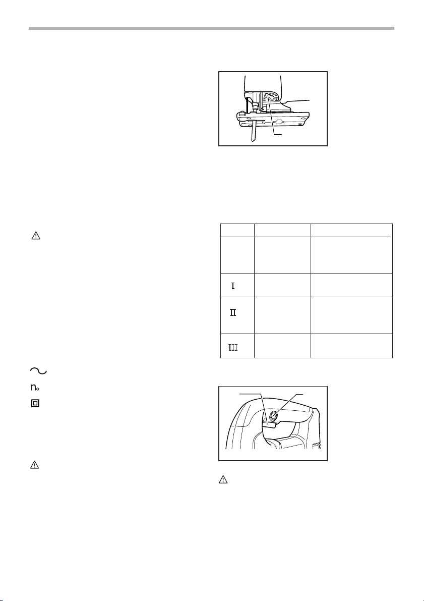
Selecting the cutting action
001906
1. Cutting action
changing lever
1
This tool can be operated with an orbital or a straight line
(up and down) cutting action. The orbital cutting action
thrusts the blade forward on the cutting stroke and
greatly increases cutting speed.
To change the cutting action, just turn the cutting action
changing lever to the desired cutting action position.
Refer to the table to select the appropriate cutting action.
Position Cutting action Applications
Straight line
cutting action
0
Small orbit
cutting action
Medium orbit
cutting action
Large orbit
cutting action
Switch action
1
For cutting mild steel,
stainless steel and plastics.
For clean cuts in wood
and plywood.
For cutting mild steel,
aluminum and hard wood.
For cutting wood and
plywood.
For fast cutting in
aluminum and mild steel.
For fast cutting in
wood and plywood.
001907
1. Switch trigger
2
2. Lock button
006376
FUNCTIONAL DESCRIPTION
CAUTION:
• Always be sure that the tool is switched off and
unplugged before adjusting or checking function on
the tool.
CAUTION:
• Before plugging in the tool, always check to see
that the switch trigger actuates properly and returns
to the “OFF” position when released.
To start the tool, simply pull the switch trigger. Release
the switch trigger to stop.
For continuous operation, pull the switch trigger and then
push in the lock button.
To stop the tool from the locked position, pull the switch
trigger fully, then release it.
4
Speed adjusting dial
001908
1. Speed adjusting dial
1
The tool speed can be infinitely adjusted between 800
and 2,800 strokes per minute by turning the adjusting
dial. Higher speed is obtained when the dial is turned in
the direction of number 5; lower speed is obtained when
it is turned in the direction of number 1.
Refer to the table to select the proper speed for the workpiece to be cut. However, the appropriate speed may differ with the type or thickness of the workpiece. In
general, higher speeds will allow you to cut workpieces
faster but the service life of the blade will be reduced.
Workpiece to be cut Number on adjusting dial
Wood 4 - 5
Mild steel 3 - 5
Stainless steel 3 - 4
Aluminum 3 - 5
Plastics 1 - 4
006368
CAUTION:
• The speed adjusting dial can be turned only as far
as 5 and back to 1. Do not force it past 5 or 1, or the
speed adjusting function may no longer work.
The tools equipped with electronic function are easy to
operate because of the following features.
Constant speed control
Electronic speed control for obtaining constant speed.
Possible to get fine finish, because the rotating speed is
kept constant even under load condition.
Soft start feature
Safety and soft start because of suppressed starting
shock.
Lighting up the lamps
For 4340FCT only
CAUTION:
• Do not look in the light or see the source of light
directly.
To turn on the lamp, pull the trigger. Release the trigger
to turn it off.
NOTE:
• Use a dry cloth to wipe the dirt off the lens of lamp.
Be careful not to scratch the lens of lamp, or it may
lower the illumination.
ASSEMBLY
CAUTION:
• Always be sure that the tool is switched off and
unplugged before carrying out any work on the tool.
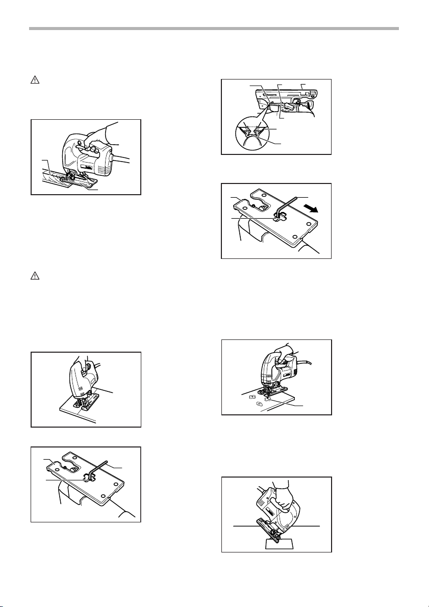
Installing or removing saw blade
CAUTION:
• Always clean out all chips or foreign matter
adhering to the blade and/or blade holder. Failure to
do so may cause insufficient tightening of the blade,
resulting in a serious personal injury.
• Do not touch the blade or the workpiece
immediately after operation; they may be extremely
hot and could burn your skin.
• Tighten the saw blade securely. Failure to do so
may cause a serious injury.
• When you remove the saw blade, be careful not to
hurt your fingers with the top of the blade or the tips
of workpiece.
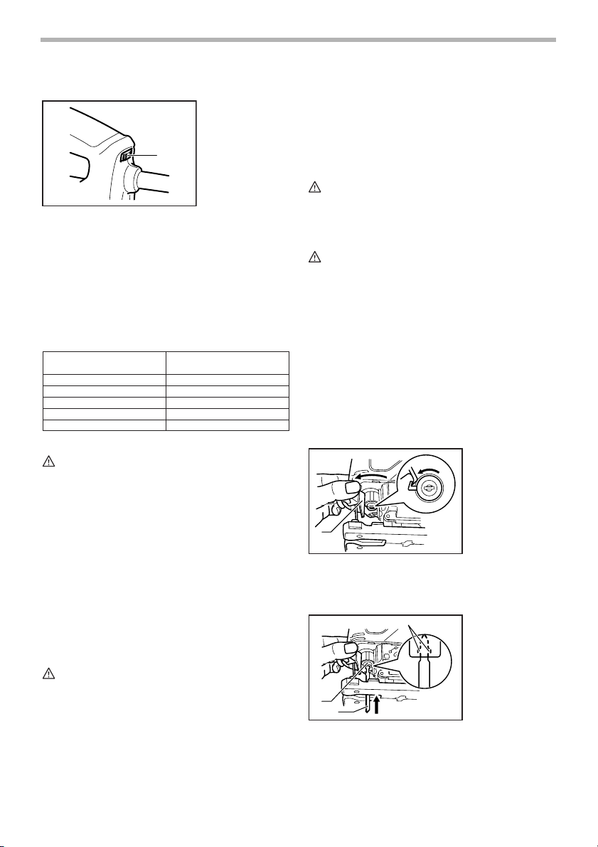
To install the blade, open the tool opener to the position
shown in the figure.
1
Keeping that situation, insert the saw blade into the blade
clamp as far as the two protrusions of the blade can not
be seen.
1
2
Return the tool opener to its original position.
After installing, always make sure that the blade is
securely held in place by trying to pull it out.
001909
1. Tool opener
001910
3
1. Blade clamp
2. Jig saw blade
3. Protrusions
5
CAUTION:
• Do not open the tool opener excessively, or it may
cause tool damage.
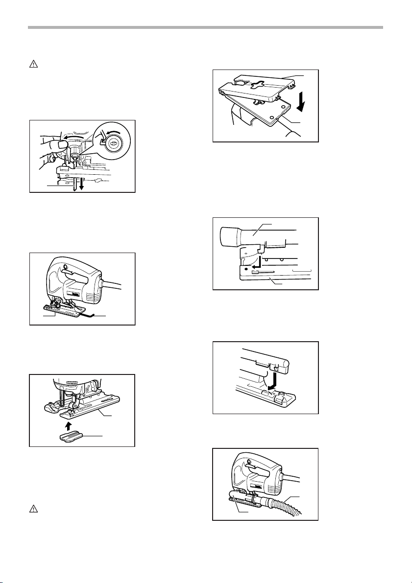
To remove the blade, open the tool opener to the position
shown in the figure. Pull the saw blade out toward the
base.
001911
1. Jig saw blade
1
NOTE:
• Occasionally lubricate the roller.
Hex wrench storage
001912
1. Base
2. Hex wrench
1
2
When not in use, store the hex wrench as shown in the
figure to keep it from being lost.
Anti-splintering device
001929
1. Base
2. Anti-splintering
device
Cover plate
001928
1
1. Cover plate
2. Base
2
Use the cover plate when cutting decorative veneers,
plastics, etc. It protects sensitive or delicate surfaces
from damage. Fit it on the back of the tool base.
Dust extraction
The dust nozzle (optional accessory) is recommended to
perform clean cutting operations.
1
To attach the dust nozzle on the tool, insert the hook of
dust nozzle into the hole in the base.
The dust nozzle can be installed on either left or right
side of the base.
001921
1. Dust nozzle
2. Base
2
001922
1
2
For splinter-free cuts, the anti-splintering device can be
used. To install the anti-splintering device, move the tool
base all the way forward and fit it from the back of tool
base. When you use the cover plate, install the anti-splintering device onto the cover plate.
CAUTION:
• The anti-splintering device cannot be used when
making bevel cuts.
Then connect a Makita vacuum cleaner to the dust nozzle.
001923
1. Dust nozzle
2. Hose for vacuum cleaner
2
1
6
OPERATION
CAUTION:
• Always hold the base flush with the workpiece.
Failure to do so may cause blade breakage,
resulting in a serious injury.
1
Turn the tool on without the blade making any contact
and wait until the blade attains full speed. Then rest the
base flat on the workpiece and gently move the tool forward along the previously marked cutting line.
When cutting curves, advance the tool very slowly.
Bevel cutting
CAUTION:
• Always be sure that the tool is switched off and
unplugged before tilting the base.
With the base tilted, you can make bevel cuts at any
angle between 0° and 45° (left or right).
Loosen the bolt on the back of the base with the hex
wrench. Move the base so that the bolt is positioned in
the center of the bevel slot in the base.
001913
1. Cutting line
2. Base
2
001914
angle by graduations. Then tighten the bolt firmly to
secure the base.
1
23
001916
1. Graduations
2. Bevel slot
3. Base
5
6
4. V-notch
5. Bolt
6. Gear housing
4
Front flush cuts
001917
1. Base
1
3
2. Bolt
3. Hex wrench
2
Loosen the bolt on the back of the base with the hex
wrench and slide the base all the way back. Then tighten
the bolt to secure the base.
Cutouts
Cutouts can be made with either of two methods A or B.
A) Boring a starting hole:
001918
1. Starting hole
001915
1
3
1. Base
2. Bolt
3. Hex wrench
2
Tilt the base until the desired bevel angle is obtained.
The V-notch of the gear housing indicates the bevel
1
For internal cutouts without a lead-in cut from an
edge, pre-drill a starting hole 12 mm (1/2”) or more
in diameter. Insert the blade into this hole to start
your cut.
B) Plunge cutting:
001919
7
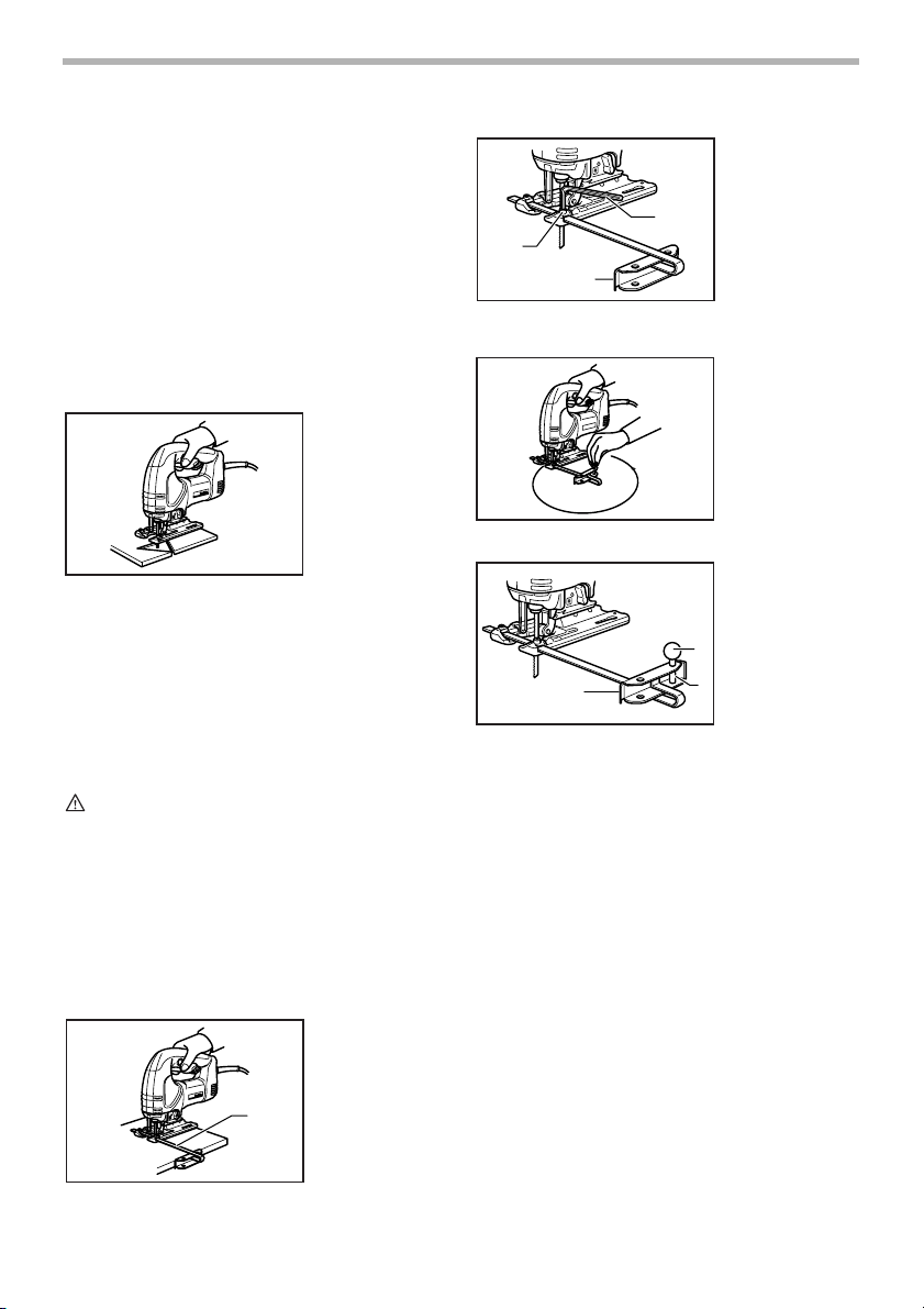
You need not bore a starting hole or make a lead-in
cut if you carefully do as follows.
(1) Tilt the tool up on the front edge of the base
with the blade point positioned just above the
workpiece surface.
(2) Apply pressure to the tool so that the front
edge of the base will not move when you
switch on the tool and gently lower the back
end of the tool slowly.
(3) As the blade pierces the workpiece, slowly
lower the base of the tool down onto the
workpiece surface.
(4) Complete the cut in the normal manner.
Finishing edges
001920
To trim edges or make dimensional adjustments, run the
blade lightly along the cut edges.
Metal cutting
Always use a suitable coolant (cutting oil) when cutting
metal. Failure to do so will cause significant blade wear.
The underside of the workpiece can be greased instead
of using a coolant.
Rip fence set (optional accessory)
CAUTION:
• Always be sure that the tool is switched off and
unplugged before installing or removing
accessories.
1. Straight cuts
When repeatedly cutting widths of 160 mm (6-5/16”) or
less, use of the rip fence will assure fast, clean, straight
cuts. To install, insert the rip fence into the rectangular
hole on the side of the tool base with the fence guide facing down. Slide the rip fence to the desired cutting width
position, then tighten the bolt to secure it.
001924
1. Rip fence
001925
1. Bolt
2. Fence guide
3. Hex wrench
3
1
2
2. Circular cuts
001926
001927
1. Fence guide
2. Threaded knob
3. Circular guide
pin
2
1
3
When cutting circles or arcs of 170 mm (6-11/16”) or less
in radius, install the rip fence as follows.
Insert the rip fence into the rectangular hole on the
side of the base with the fence guide facing up.
Insert the circular guide pin through either of the
two holes on the fence guide. Screw the threaded
knob onto the pin to secure the pin.
Now slide the rip fence to the desired cutting radius,
and tighten the bolt to secure it in place. Then move
the base all the way forward.
NOTE:
• Always use blades No. B-17, B-18, B-26 or B-27
when cutting circles or arcs.
1
8

MAINTENANCE
CAUTION:
• Always be sure that the tool is switched off and
unplugged before attempting to perform inspection
or maintenance.
To maintain product SAFETY and RELIABILITY, repairs,
carbon brush inspection and replacement, any other
maintenance or adjustment should be performed by Makita Authorized or Factory Service Centers, always using
Makita replacement parts.
ACCESSORIES
CAUTION:
• These accessories or attachments are
recommended for use with your Makita tool
specified in this manual. The use of any other
accessories or attachments might present a risk of
injury to persons. Only use accessory or
attachment for its stated purpose.
If you need any assistance for more details regarding
these accessories, ask your local Makita Service Center.
• Jig saw blades
• Hex wrench
• Rip fence (guide rule) set
• Cover plate
• Anti-splintering device
• Dust nozzle
MAKITA LIMITED ONE YEAR WARRANTY
EN0006-1
Warranty Policy
Every Makita tool is thoroughly inspected and tested
before leaving the factory. It is warranted to be free of
defects from workmanship and materials for the period of
ONE YEAR from the date of original purchase. Should
any trouble develop during this one year period, return
the COMPLETE tool, freight prepaid, to one of Makita’s
Factory or Authorized Service Centers. If inspection
shows the trouble is caused by defective workmanship or
material, Makita will repair (or at our option, replace)
without charge.
This Warranty does not apply where:
• repairs have been made or attempted by others:
• repairs are required because of normal wear and
tear:
• the tool has been abused, misused or improperly
maintained:
• alterations have been made to the tool.
IN NO EVENT SHALL MAKITA BE LIABLE FOR ANY
INDIRECT, INCIDENTAL OR CONSEQUENTIAL DAMAGES FROM THE SALE OR USE OF THE PRODUCT.
THIS DISCLAIMER APPLIES BOTH DURING AND
AFTER THE TERM OF THIS WARRANTY.
MAKITA DISCLAIMS LIABILITY FOR ANY IMPLIED
WARRANTIES, INCLUDING IMPLIED WARRANTIES
OF “MERCHANTABILITY” AND “FITNESS FOR A SPECIFIC PURPOSE,” AFTER THE ONE YEAR TERM OF
THIS WARRANTY.
This Warranty gives you specific legal rights, and you
may also have other rights which vary from state to state.
Some states do not allow the exclusion or limitation of
incidental or consequential damages, so the above limitation or exclusion may not apply to you. Some states do
not allow limitation on how long an implied warranty lasts,
so the above limitation may not apply to you.
9
 Loading...