

Page 1
Cordless Jig Saw
MODEL 4334D
INSTRUCTION MANUAL
WARNING:
For your personal safety, READ and UNDERSTAND before using.
SAVE THESE INSTRUCTIONS FOR FUTURE REFERENCE.
www.makitatools.com
Page 2

SPECIFICATIONS
Model 4334D
Length of stroke 26 mm (1”)
Wood 135 mm (5-5/16”)
Max. cutting capacities
Strokes per minute 500 - 2,800/min
Overall length 281 mm (11”)
Net weight 3.4 kg (7.5 lbs)
Battery Charger DC1804
Input A. C. only 50 Hz - 60 Hz
Output D. C. 7.2 V - 18 V
Battery Cartridge 1822 1834 1835
Voltage 18 V
Charging time 45 min. 60 min. 70 min.
• Manufacturer reserves the right to change specifications without notice.
• Specifications may differ from country to country.
Mild steel 10 mm (3/8”)
Aluminum 20 mm (13/16”)
GENERAL SAFETY RULES USA003-1
(FOR All BATTERY OPERATED TOOLS)
WARNING:
Read and understand all instructions. Failure to follow all
instructions listed below, may result in electric shock, fire and/or
serious personal injury.
SAVE THESE INSTRUCTIONS
2
Page 3

Work Area
1. Keep your work area clean and well lit.
Cluttered benches and dark areas invite accidents.
2. Do not operate power tools in explosive
atmospheres, such as in the presence of
flammable liquids, gases, or dust. Powe r
tools create sparks which may ignite the dust
or fumes.
3. Keep bystanders, children, and visitors
away while operating a power tool. Distrac-
tions can cause you to lose control.
Electrical Safety
4. A battery operated tool with integral batteries or a separate battery pack must be
recharged only with the specified charger
for the battery. A charger that may be suit-
able for one type of battery may create a risk
of fire when used with another battery.
5. Use battery operated tool only with specifically designated battery pack. Use of any
other batteries may create a risk of fire.
Personal Safety
6. Stay alert, watch what you are doing, and
use common sense when operating a
power tool. Do not use tool while tired or
under the influence of drugs, alcohol, or
medication. A moment of inattention while
operating power tools may result in serious
personal injury.
7. Dress properly. Do not wear loose clothing or jewelry. Contain long hair. Keep
your hair, clothing, and gloves away from
moving parts. Loose clothes, jewelry, or long
hair can be caught in moving parts.
8. Avoid accidental starting. Be sure switch
is in the locked or off position before
inserting battery pack. Carrying tools with
your finger on the switch or inserting the battery pack into a tool with the switch on invites
accidents.
9. Remove adjusting keys or wrenches
before turning the tool on. A wrench or a
key that is left attached to a rotating part of
the tool may result in personal injury.
10. Do not overreach. Keep proper footing
and balance at all times. Proper footing and
balance enable better control of the tool in
unexpected situations.
11. Use safety equipment. Always wear eye
protection. Dust mask, non-skid safety
shoes, hard hat, or hearing protection must
be used for appropriate conditions.
Tool Use and Care
12. Use clamps or other practical way to
secure and support the workpiece to a
stable platform. Holding the work by hand or
against your body is unstable and may lead
to loss of control.
13. Do not force tool. Use the correct tool for
your application. The correct tool will do the
job better and safer at the rate for which it is
designed.
14. Do not use tool if switch does not turn it
on or off. A tool that cannot be controlled
with the switch is dangerous and must be
repaired.
15. Disconnect battery pack from tool or
place the switch in the locked or off position before making any adjustments,
changing accessories, or storing the tool.
Such preventive safety measures reduce the
risk of starting the tool accidentally.
16. Store idle tools out of reach of children
and other untrained persons. Tools are
dangerous in the hands of untrained users.
17. When battery pack is not in use, keep it
away from other metal objects like: paper
clips, coins, keys, nails, screws, or other
small metal objects that can make a connection from one terminal to another.
Shorting the battery terminals together may
cause sparks, burns, or a fire.
3
Page 4

18. Maintain tools with care. Keep cutting
tools sharp and clean. Properly maintained
tools with sharp cutting edge are less likely to
bind and are easier to control.
19. Check for misalignment or binding of
moving parts, breakage of parts, and any
other condition that may affect the tool’s
operation. If damaged, have the tool serviced before using. Many accidents are
caused by poorly maintained tools.
20. Use only accessories that are recommended by the manufacturer for your
model. Accessories that may be suitable for
one tool may create a risk of injury when
used on another tool.
SERVICE
21. Tool service must be performed only by
qualified repair personnel. Service or main-
tenance performed by unqualified personnel
may result in a risk of injury.
22. When servicing a tool, use only identical
replacement parts. Follow instructions in
the Maintenance section of this manual.
Use of unauthorized parts or failure to follow
Maintenance instructions may create a risk of
shock or injury.
ADDITIONAL SAFETY RULES USB030-2
DO NOT let comfort or familiarity with product (gained from
repeated use) replace strict adherence to cordless jig saw
safety rules. If you use this tool unsafely or incorrectly, you can
suffer serious personal injury.
1. Hold tool by insulated gripping surfaces
when performing an operation where the
cutting tool may contact hidden wiring.
Contact with a “live” wire will make
exposed metal parts of the tool “live” and
shock the operator.
2. Be aware that this tool is always in an
operating condition, because it does not
have to be plugged into an electrical outlet.
3. Always use safety glasses or goggles.
Ordinary eye or sun glasses are NOT
safety glasses.
4. Avoid cutting nails. Inspect for and
remove all nails from the workpiece
before operation.
5. Do not cut hollow pipe.
6. Do not cut oversize workpiece.
7. Check for the proper clearance beneath
the workpiece before cutting so that the
blade will not strike the floor, workbench,
etc.
8. Hold the tool firmly.
9. Check the blade is not contacting the
workpiece before the switch is turned on.
10. Keep hands away from moving parts.
11. Do not leave the tool running. Operate the
tool only when hand-held.
12. Always switch off and wait for the blade to
come to a complete stop before removing
the blade from the workpiece.
13. Do not touch the blade or the workpiece
immediately after operation; they may be
extremely hot and could burn your skin.
4
Page 5

14. Some material contains chemicals which
may be toxic. Take caution to prevent
dust inhalation and skin contact. Follow
material supplier safety data.
SAVE THESE INSTRUCTIONS
WARNING:
MISUSE or failure to follow the safety rules stated in this
instruction manual may cause serious personal injury.
SYMBOLS USD301-1
The followings show the symbols used for tool.
V .......................volts
................... direct current
....................no load speed
n
˚
.../min................revolutions or reciprocation per
minute
IMPORTANT SAFETY INSTRUCTIONS FOR
CHARGER & BATTERY CARTRIDGE
1. SAVE THESE INSTRUCTIONS - This manual contains important safety and operating instructions for battery charger.
2. Before using battery charger, read all
instructions and cautionary markings on
(1) battery charger, (2) battery, and (3)
product using battery.
3. CAUTION - To reduce risk of injury, charge
only MAKITA rechargeable batteries
marked on the charger label. Other types
of batteries may burst causing personal
injury and damage.
4. Do not expose charger to rain or snow.
5. Use of an attachment not recommended
or sold by the battery charger manufacturer may result in a risk of fire, electric
shock, or injury to persons.
6. To reduce risk of damage to electric plug
and cord, pull by plug rather than cord
when disconnecting charger.
USC001-3
5
Page 6

7. Make sure cord is located so that it will
not be stepped on, tripped over, or otherwise subjected to damage or stress.
8. An extension cord should not be used
unless absolutely necessary. Use of
improper extension cord could result in a
risk of fire and electric shock. If extension
cord must be used, make sure:
Table 1: RECOMMENDED MINIMUM AWG SIZE FOR EXTENSION CORDS FOR BATTERY CHARGERS
Length of Cord (Feet) 25 50 100 150
AWG Size of Cord 18 18 18 16
a. That pins on plug of extension cord
are the same number, size, and shape
as those of plug on charger;
b. That extension cord is properly wired
and in good electrical condition;
c. That wire size is at least as large as
the one specified in the table below.
9. Do not operate charger with damaged
cord or plug - replace them immediately.
10. Do not operate charger if it has received a
sharp blow, been dropped, or otherwise
damaged in any way; take it to a qualified
serviceman.
11. Do not disassemble charger or battery
cartridge; take it to a qualified serviceman
when service or repair is required, Incorrect reassembly may result in a risk of
electric shock or fire.
12. To reduce risk of electric shock, unplug
charger from outlet before attempting any
maintenance or cleaning. Turning off controls will not reduce this risk.
13. The battery charger is not intended for
use by young children or infirm persons
without supervision.
14. Young children should be supervised to
ensure that they do not play with the battery charger.
15. If operating time has become excessively
shorter, stop operating immediately. It
may result in a risk of overheating, possible burns and even an explosion.
16. If electrolyte gets into your eyes, rinse
them out with clear water and seek medical attention right away. It may result in
loss of your eyesight.
ADDITIONAL SAFETY RULES FOR CHARGER &
BATTERY CARTRIDGE
1. Do not charge Battery Cartridge when
temperature is BELOW 10°C (50°F) or
ABOVE 40°C (104°F).
2. Do not attempt to use a step-up transformer, an engine generator or DC power
receptacle.
3. Do not allow anything to cover or clog the
charger vents.
4. Always cover the battery terminals with
the battery cover when the battery cartridge is not used.
5. Do not short the battery cartridge:
6
Page 7

(1) Do not touch the terminals with any
conductive material.
(2) Avoid storing battery cartridge in a
container with other metal objects
such as nails, coins, etc.
(3) Do not expose battery cartridge to
water or rain.
A battery short can cause a large current
flow, overheating, possible burns and
even a breakdown.
6. Do not store the tool and Battery Cartridge in locations where the temperature
may reach or exceed 50°C (122°F).
7. Do not incinerate the Battery Cartridge
even if it is severely damaged or is completely worn out. The battery cartridge can
explode in a fire.
8. Be careful not to drop, shake or strike battery.
9. Do not charge inside a box or container of
any kind. The battery must be placed in a
well ventilated area during charging.
SAVE THESE INSTRUCTIONS
7
Page 8
FUNCTIONAL
DESCRIPTION
1
2
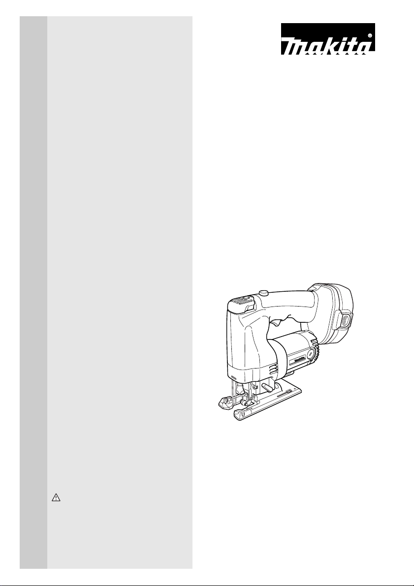
1. Button
2. Battery cartridge
1
2
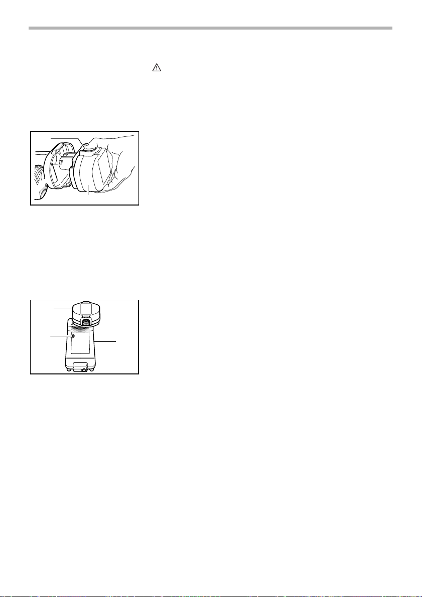
1. Battery cartridge
2. Charging light
3. Battery charger
3
CAUTION:
• Always be sure that the tool is switched off and the
battery cartridge is removed before adjusting or
checking function on the tool.
002703
Installing or removing battery cartridge
• Always switch off the tool before insertion or removal of
the battery cartridge.
• To remove the battery cartridge, withdraw it from the tool
while pressing the buttons on both sides of the cartridge.
• To insert the battery cartridge, align the tongue on the
battery cartridge with the groove in the housing and slip
it into place. Always insert it all the way until it locks in
place with a little click. If not, it may accidentally fall out
of the tool, causing injury to you or someone around you.
• Do not use force when inserting the battery cartridge. If
the cartridge does not slide in easily, it is not being
inserted correctly.
004346
Charging
1. Plug the battery charger into the proper AC voltage
source. The charging light will flash in green color.
2. Insert the battery cartridge so that the plus and minus
terminals on the battery cartridge are on the same sides
as their respective markings on the charger. Insert the
cartridge fully into the port so that it rests on the charger
port floor.
3. When the battery cartridge is inserted, the charging light
color will change from green to red and charging will
begin. The charging light will remain lit steadily during
charging.
4. When the charging light color changes from red to
green, the charging cycle is complete.
5. If you leave the battery cartridge in the charger after the
charging cycle is complete, the charger will switch into
its “trickle charge (maintenance charge)” mode.
6. After charging, unplug the charger from the power
source.
8
Page 9

NOTE:
• The battery charger is for charging Makita battery
cartridge. Never use it for other purposes or for other
manufacturer’s batteries.
• When you charge a new battery cartridge or a battery
cartridge which has not been used for a long period of
time, it may not accept a full charge. This is a normal
condition and does not indicate a problem. You can
recharge the battery cartridge fully after discharging it
completely and recharging a couple of times.
• If you charge a battery cartridge from a just operated
tool or a battery cartridge which has been left in a
location exposed to direct sunlight or heat for a long
time, the charging light may flash in red color. If this
occurs, wait for a while. Charging will begin after the
battery cartridge cools. The battery cartridge will cool
faster if you remove the battery cartridge from the
battery charger.
• If the charging light flashes alternately in green and red
color, charging is not possible. The terminals on the
charger or battery cartridge are clogged with dust or the
battery cartridge is worn out or damaged.
Trickle charge (Maintenance charge)
If you leave the battery cartridge in the charger to prevent
spontaneous discharging after full charge, the charger will
switch into its “trickle charge (maintenance charge)” mode
and keep the battery cartridge fresh and fully charged.
Tips for maintaining maximum battery life
1. Charge the battery cartridge before completely discharged.
Always stop tool operation and charge the battery cartridge when you notice less tool power.
2. Never recharge a fully charged battery cartridge.
Overcharging shortens the battery service life.
3. Charge the battery cartridge with room temperature at
10°C - 40°C (50°F - 104°F).
Let a hot battery cartridge cool down before charging it.
4. Charge the Nickel Metal Hydride battery cartridge when
you do not use it for more than six months.
9
Page 10

1
1. Cutting action changing lever
002706
Selecting the cutting action
This tool can be operated with an orbital or a straight line (up
and down) cutting action. The orbital cutting action thrusts
the blade forward on the cutting stroke and greatly increases
cutting speed.
To change the cutting action, just turn the cutting action
changing lever to the desired cutting action position. Refer to
the table to select the appropriate cutting action.
1
2
1. Lock-off button
2. Switch trigger
1. Speed adjusting dial
Position
0
I
II
III
Cutting action
Straight line cutting action
Small orbit cutting action
Medium orbit cutting action
Large orbit cutting action
002709
Switch action
For cutting mild steel, stainless steel and plastics.
For clean cuts in wood and plywood.
For cutting mild steel, aluminum and hard wood.
For cutting wood and plywood.
For fast cutting in aluminum and mild steel.
For fast cutting in wood and plywood.
Applications
CAUTION:
• Before inserting the battery cartridge into the tool,
always check to see that the switch trigger actuates
properly and returns to the “OFF” position when
released.
To prevent the switch trigger from being accidentally pulled, a
lock-off button is provided.
To start the tool, depress the lock-off button and pull the
switch trigger. Release the switch trigger to stop.
002712
Speed adjusting dial
The tool speed can be infinitely adjusted between 500 and
1
2,800 strokes per minute by turning the adjusting dial. Higher
speed is obtained when the dial is turned in the direction of
number 5; lower speed is obtained when it is turned in the
direction of number 1.
Refer to the table to select the proper speed for the workpiece to be cut. However, the appropriate speed may differ
with the type or thickness of the workpiece. In general, higher
speeds will allow you to cut workpieces faster but the service
life of the blade will be reduced.
002788
10
Page 11

Workpiece to be cut
0
Wood
Mild steel
Stainless steel
Aluminum
Plastics
Number on adjusting dial
3 - 5
3 - 5
3 - 4
2 - 3
1 - 4
00279
CAUTION:
• If the tool is operated continuously at low speeds for a
long time, the motor will get overloaded and heated up.
• The speed adjusting dial can be turned only as far as 5
and back to 1. Do not force it past 5 or 1, or the speed
adjusting function may no longer work.
ASSEMBLY
(1)
1
CAUTION:
• Always be sure that the tool is switched off and the
battery cartridge is removed before carrying out any
work on the tool.
Installing or removing saw blade
CAUTION:
• Always clean out all chips or foreign matter adhering to
the blade and/or blade holder. Failure to do so may
cause insufficient tightening of the blade, resulting in a
serious personal injury.
• Do not touch the blade or the workpiece immediately
after operation; they may be extremely hot and could
burn your skin.
• Always secure the blade firmly. Insufficient tightening of
the blade may cause blade breakage or serious personal
injury.
002719
Installation
1. Push the blade installing lever in the (1) direction to
release it.
1. Blade installing lever
11
Page 12

(4)
002720
2. Pull the blade installing lever in the (2) direction until it
stops with a little click. If you have difficulty pulling it out,
(3)
(2)
try to do so while moving it back and forth in the (3)
direction.
3. Rotate the blade installing lever in the (4) direction until
the clamp protrudes 5 - 7 mm from the blade holder.
CAUTION:
• If you rotate the blade installing lever excessively, the
clamp will also rotate and finally come off. In this case,
re-install it properly as lately described in ’’Installing
clamp’’.
002721
1
2
3
4. With the blade teeth facing forward, insert the blade into
the blade holder as far as it will go. Make sure that the
back edge of the blade fits properly into the groove of the
roller.
1. Blade holder
2. Clamp
3. Slot
4. Roller
5. Blade
(5)
1. Blade installing lever
2. Blade
(6)
1. Blade installing lever
4
1
2
1
5
002722
002723
5. With the blade held against the blade holder, rotate the
blade installing lever in the (5) direction until it stops.
6. With the blade installing lever held in this position, push
it in the (6) direction. Then rotate the blade installing
lever to its original position.
12
Page 13

(1)
1
1. Blade installing lever
(3)
(2)
(4)
002719
002720
Removal
1. Push the blade installing lever in the (1) direction to
release it.
2. Pull the blade installing lever in the (2) direction until it
stops with a little click. If you have difficulty pulling it out,
try to do so while moving it back and forth in the (3)
direction.
3. Rotate the blade installing lever in the (4) direction and
remove the blade.
1
(5)
1. Blade installing lever
1
(6)
1. Blade installing lever
1. Base
2. Anti-splintering device
002724
4. Rotate the blade installing lever in the (5) direction until it
stops.
002723
5. With the blade installing lever held in this position, push
it in the (6) direction. Then rotate the blade installing
lever to its original position.
002734
Anti-splintering device
For splinter-free cuts, the anti-splintering device can be used.
To install the anti-splintering device, move the base all the
1
way forward and fit it into the base from the back of base.
NOTE:
2
• The anti-splintering device cannot be used when making
bevel cuts.
13
Page 14

1. Screw
2. Plastic base plate
1
2
3
1. Hex wrench
2. Bolt
3. Rip fence (Guide rule)
1. Threaded knob
2. Circular guide
3. Pin
002736
Plastic base plate (optional accessory)
1
Use the plastic base plate when cutting decorative veneers,
plastics, etc. It protects sensitive surfaces from damage. To
2
replace the base plate, remove the four screws.
002738
Rip fence (optional accessory)
When cutting widths of under 150 mm (5 - 29/32”) repeatedly, use of the rip fence (guide rule) will assure fast, clean,
straight cuts. To install it, loosen the bolt on the front of the
base. Slip in the rip fence and secure the bolt.
002739
Circular guide (optional accessory)
1
Use of the circular guide insures clean, smooth cutting of circles under 200 mm (7 - 7/8”) in radius. Insert the pin through
2
3
the center hole and secure it with the threaded knob. Move
the base of the tool forward fully. Then install the circular
guide on the base in the same manner as the rip fence
(guide rule).
1. Notches
2. Base
3. Plastic cover
14
002740
Vacuum head (optional accessory)
The vacuum head is recommended to perform clean cutting
1
operations. Install the plastic cover on the tool by fitting it into
the notches in the tool.
2
3
Page 15

2
1. Vacuum head
2. Base
002741
To attach the vacuum head on the tool, insert the hooks of
1
the vacuum head into the hole in the base. The vacuum head
can be installed on either left or right side of the base.
Then connect a Makita vacuum cleaner to the vacuum head.
002742
OPERATION
1
1. Cutting line
2. Base
2
CAUTION:
• Always hold the base flush with the workpiece. Failure to
do so may cause blade breakage, resulting in a serious
injury.
• Advance the tool very slowly when cutting curves or
scrolling. Forcing the tool may cause a slanted cutting
surface and blade breakage.
002745
Turn the tool on without the blade making any contact and
wait until the blade attains full speed. Then rest the base flat
on the workpiece and gently move the tool forward along the
previously marked cutting line.
NOTE:
• If the tool is operated continuously until the battery
cartridge has discharged, allow the tool to rest for 15
minutes before proceeding with a fresh battery.
15
Page 16

1
1. Base securing lever
1
23
1. Dent mark
2. Slot
3. Graduation
002754
Bevel cutting
CAUTION:
• Always be sure that the tool is switched off and the
battery cartridge is removed before tilting the base.
With the base tilted, you can make bevel cuts at any angle
between 0° and 45° (left or right).
Loosen the base securing lever and move the base so that
the dent mark in the motor housing is aligned with the slot in
the base.
002755
Tilt the base until the desired bevel angle is obtained. The
edge of the motor housing indicates the bevel angle by graduations. Then tighten the base securing lever to secure the
base.
NOTE:
• Always remove the plastic cover (chip shield) from the
tool when you make bevel cuts using an optional rip
fence (guide rule) or circular guide.
002759
Front flush cuts
Loosen the base securing lever and slide the base all the
way back. Then tighten the base securing lever to secure the
base.
1
1. Starting hole
16
Cutouts
Cutouts can be made with either of two methods A or B.
002765
A) Boring a starting hole
For internal cutouts without a lead-in cut from an edge,
pre-drill a starting hole 12 mm (1/2”) or more in diameter.
Insert the blade into this hole to start your cut.
Page 17

002766
B) Plunge cutting
You need not bore a starting hole or make a lead-in cut if
you carefully do as follows.
(1) Tilt the tool up on the front edge of the base with the
blade point positioned just above the workpiece surface.
(2) Apply pressure to the tool so that the front edge of
the base will not move when you switch on the tool
and gently lower the back end of the tool slowly.
(3) As the blade pierces the workpiece, slowly lower the
base of the tool down onto the workpiece surface.
(4) Complete the cut in the normal manner.
002770
Finishing edges
To trim edges or make dimensional adjustments, run the
blade lightly along the cut edges.
Metal cutting
Always use a suitable coolant (cutting oil) when cutting
metal. Failure to do so will cause significant blade wear. The
underside of the workpiece can be greased instead of using
a coolant.
MAINTENANCE
CAUTION:
• Always be sure that the tool is switched off and the
battery cartridge is removed before attempting to
perform inspection or maintenance.
Cleaning clamp on blade holder
If chips or foreign matter get into the clamp on the blade
holder, clean out the clamp after removing it from the blade
holder.
17
Page 18

(1)
1
1. Blade installing lever
(3)
(2)
(4)
002719
Removing clamp
1. Push the blade installing lever in the (1) direction to
002720
2. Pull the blade installing lever in the (2) direction until it
release it.
stops with a little click. If you have difficulty pulling it out,
try to do so while moving it back and forth in the (3)
direction.
2
1. Blade holder
2. Clamp
1
2
(5)
1. Blade holder
2. Clamp
002993
1
002781
3. Rotate the blade installing lever in the (4) direction until it
stops. The clamp will protrude from the blade holder.
4. Remove the clamp from the blade holder while rotating
the clamp in the (5) direction.
18
Page 19

(4)
Installing clamp
002782
1. Make sure that the blade installing lever has been
rotated in the (4) direction until it stops.
1
2
1. Blade holder
2. Clamp
1
(7)
1. Blade installing lever
(6)
002783
2. Insert the clamp into the blade holder while rotating it in
the (6) direction one quarter to one full turn so that its
slot will face forward.
CAUTION:
• Do not rotate the clamp more than one full turn when
inserting in into the blade holder. If you do so, the blade
may not be tightened firmly.
002784
3. Grasp the clamp with your fingers so that it will not turn,
then rotate the blade installing lever in the (7) direction
until it stops. The clamp will go in the blade holder.
001145
Replacing carbon brushes
Remove and check the carbon brushes regularly. Replace
when they wear down to the limit mark. Keep the carbon
brushes clean and free to slip in the holders. Both carbon
brushes should be replaced at the same time. Use only iden-
1
tical carbon brushes.
1. Limit mark
19
Page 20

1. Brush holder cap
2. Screwdriver
Ni-Cd
002786
Use a screwdriver to remove the brush holder caps. Take out
the worn carbon brushes, insert the new ones and secure
the brush holder caps.
1
To maintain product SAFETY and RELIABILITY, repairs, any
other maintenance or adjustment should be performed by
Makita Authorized or Factory Service Centers, always using
2
Makita replacement parts.
EN0001-1
Recycling the Battery
The only way to dispose of a Makita battery is to recycle it.
The law prohibits any other method of disposal.
To recycle the battery:
1. Remove the battery from the tool.
2. a) Take the battery to your nearest Makita Factory Ser-
vice Center
or
b) Take the battery to your nearest Makita Authorized
Service Center or Distributor that has been designated as a Makita battery recycling location.
Call your nearest Makita Service Center or Distributor to
determine the location that provides Makita battery recycling.
See your local Yellow Pages under “Tools-Electric”.
20
Page 21

ACCESSORIES
CAUTION:
• These accessories or attachments are recommended for
use with your Makita tool specified in this manual. The
use of any other accessories or attachments might
present a risk of injury to persons. Only use accessory
or attachment for its stated purpose.
If you need any assistance for more details regarding these
accessories, ask your local Makita service center.
• Jig saw blades
• Various type of Makita genuine batteries and chargers
• Hex wrench 3
• Rip fence (guide rule) set
• Circular guide set
• Plastic base plate
• Anti-splintering device
• Plastic cover
• Vacuum head
• Hose (For vacuum cleaner)
21
Page 22

Memo
22
Page 23

Memo
23
Page 24

Memo
24
Page 25

Cut
Makita U.S.A., Inc.
14930 Northam Street
La Mirada, CA 90638-5753
Fold
First-Class
Postage
Required
Post Office will
not deliver
without proper
postage.
25
Page 26

MAIL THIS PORTION
Your answers to the following questions are appreciated.
1. This product was purchased from:
Home Center
Hardware/Lumber Store
Tool Distributor
Industrial Supply
Construction Supply
2. Use of the product is intended for:
Construction Trade
Industrial Maintenance
Home Maintenance
Hobby
Other ( )
5. Any comments:
DATE PURCHASED MODEL NO.
MONTH DAY YEAR
INTL. LAST NAME / COMPANY NAME
Other ( )
3. How did you learn about this product:
4. Most favored points are:
SERIAL NO.
Magazine
From Dealer
Newspaper
Store Display
Catalog
Design
Features
Size
Price
Makita Brand
Radio
Exhibition
From Friend
Previous Usage
Other ( )
Repair Service
Durability
Powe r
Other ( )
STATUS
Married
Single
SEX
MF
STREET ADRESS
CITY
AREA
S TATE
AGE:
BE SURE TO COMPLETE THE CUSTOMER’S PORTION OF THIS FORM AND RETAIN FOR YOUR RECORDS.
Paste Paste Paste Paste Paste Paste
26
Under 19 20-29 30-39 40-49 50-60 Over 60
Please return this portion by facsimile or mail.
Facsimile No: (714) 522-8133
ZIP CODE PHONE
CODE
Paste Paste Paste Paste Paste Paste Paste Paste
Paste Paste Paste Paste Paste Paste
Page 27

FACTORY SERVICE CENTERS
1-800-4-MAKITA
RETAIN THIS PORTION FOR YOUR RECORDS
ARIZONA
3707 E. Broadway Rd., Ste. 6
Phoenix, AZ 85040
(602) 437-2850
CALIFORNIA
41850 Christy St.
Fremont, CA 94538-5107
(510) 657-9881
14930 Northam St.
La Mirada, CA 90638-5753
(714) 522-8088
1970 Fulton Avenue
Sacramento, CA 95825
(916) 482-5197
7674 Clairemont Mesa Blvd.
San Diego, CA 92111
(858) 278-4471
16735 Saticoy St., Ste. 105
Van Nuys, CA 91406
(818) 782-2440
COLORADO
11839 E. 51st Ave.
Denver, CO 80239-2709
(303) 371-2850
FLORIDA
750 East Sample Road
Pompano Beach, FL 33064
(954) 781-6333
GEORGIA
4680 River Green Parkway NW
Duluth, GA 30096
(770) 476-8911
ILLINOIS
1450 Feehanville Dr.
Mt. Prospect, IL 60056-6011
(847) 297-3100
MARYLAND
7397 Washington Boulevard,
Suite 104 Elkridge, MD 21075
(410) 796-4401
MASSACHUSETTS
232 Providence Hwy.
Westwood, MA 02090
(781) 461-9754
MINNESOTA
6427 Penn Ave. South
Richfield, MN 55423
(612) 869-5199
MISSOURI
9876 Watson Road
St. Louis, MO 63126-2221
(314) 909-9889
NEBRASKA
4129 S. 84th St.
Omaha, NE 68127
(402) 597-2925
NEVADA
3375 S. Decatur Blvd.
Suites. 22 - 24
Las Vegas, NV 89102
(702) 368-4277
NEW JERSEY
251 Herrod Blvd.
Dayton, NJ 08810-1539
(609) 655-1212
NEW YORK
4917 Genessee Street
Cheektowaga, NY 14225
(716) 685-9503
OREGON
828 19th Avenue, N.W.
Portland, OR 97209
(503) 222-1823
PENNSYLVANIA
1704 Babcock Blvd.
Pittsburgh, PA 15209
(412) 822-7370
PUERTO RICO
200 Guayama St.
Hato Rey, PR 00917
(787) 250-8776
TENNESSEE
1120 Elm Hill P.
Suile 170 Nashville, TN 372
(615) 248-3321
TEXAS
12801 Stemmons Fwy Ste. 809
Farmers Branch, TX 75234
(972) 243-1150
12701 Directors Dr.
Stafford, TX 77477-3701
(281) 565-8665
3453 IH-35 North, Ste. 101
San Antonio, TX 78219
(210) 228-0676
WISCONSIN
Lincoln Plaza Shopping Ctr.
2245 S. 108th St. West Allis, WI
53227
(414) 541-4776
CUSTOMER’S RECORD
When you need service: Send
complete tool (prepaid) to one
of the Makita Factory Service
Centers listed, or to an Authorized
Makita Service Center. Be sure
to attach a letter to the outside of
the carton detailing the problem
with your tool.
Date Purchased
Dealer’s Name & Address
Model No.
Serial No.
27
Page 28

WARNING
Some dust created by power sanding, sawing, grinding, drilling, and other
construction activities contains chemicals known to the State of California
to cause cancer, birth defects or other reproductive harm. Some examples
of these chemicals are:
• lead from lead-based paints,
• crystalline silica from bricks and cement and other masonry products, and
• arsenic and chromium from chemically-treated lumber.
Your risk from these exposures varies, depending on how often you do this
type of work. To reduce your exposure to these chemicals: work in a well
ventilated area, and work with approved safety equipment, such as those
dust masks that are specially designed to filter out microscopic particles.
MAKITA LIMITED ONE YEAR WARRANTY
Warranty Policy
Every Makita tool is thoroughly inspected and tested before leaving the factory. It is warranted to be free of
defects from workmanship and materials for the period of ONE YEAR from the date of original purchase.
Should any trouble develop during this one year period, return the COMPLETE tool, freight prepaid, to one of
Makita’s Factory or Authorized Service Centers. If inspection shows the trouble is caused by defective
workmanship or material, Makita will repair (or at our option, replace) without charge.
This Warranty does not apply where:
• repairs have been made or attempted by others:
• repairs are required because of normal wear and tear:
• the tool has been abused, misused or improperly maintained:
• alterations have been made to the tool.
IN NO EVENT SHALL MAKITA BE LIABLE FOR ANY INDIRECT, INCIDENTAL OR CONSEQUENTIAL
DAMAGES FROM THE SALE OR USE OF THE PRODUCT. THIS DISCLAIMER APPLIES BOTH DURING
AND AFTER THE TERM OF THIS WARRANTY.
MAKITA DISCLAIMS LIABILITY FOR ANY IMPLIED WARRANTIES, INCLUDING IMPLIED WARRANTIES OF
“MERCHANTABILITY” AND “FITNESS FOR A SPECIFIC PURPOSE,” AFTER THE ONE YEAR TERM OF THIS
WARRANTY.
This Warranty gives you specific legal rights, and you may also have other rights which vary from state to state.
Some states do not allow the exclusion or limitation of incidental or consequential damages, so the above
limitation or exclusion may not apply to you. Some states do not allow limitation on how long an implied
warranty lasts, so the above limitation may not apply to you.
884361C066
Makita Corporation of America
2650 Buford Hwy., Buford, GA 30518
 Loading...