

Makita 4329 KX 1 User Manual [ru]
4326
4327
4328
4329
Jig Saw
Instruction Manual
Stichsäge
Betriebsanleitung
Piła włośnica
Instrukcja obsługi
Лобзик
Инструкция по эксплуатации
2
1
3
12
4
5
6
7
34
10
6
7
8
9
56
8
9
11
7
6
12
13
78
2
14
12
910
7
6
12
11 12
7
6
12
13 14
15
16
17
15 16
3
19
13
18
17 18
21
20
19 20
21
6
23
7
20
20
19
7
22
6
20
19
24
22
20
25
21 22
21
24
23
25
20
23 24
4
19
20
21
20
25 26
26
27
29
28
26
27 28
28
5

Symbols
The followings show the symbols used for the tool. Be sure that you understand their meaning before use.
Symbole
Die folgenden Symbole werde n für die Masch ine verwendet. Mache n Sie sich vor der Benutzung unbe dingt mit ihrer
Bedeutung vertraut.
Symbole
Poniższe symbole używane są do opisu urządzenia. Przed użyciem należy upewnić się, że rozumie się ich znaczenie.
Символы
Следующие объяснения показывают символы, используемые для инструмента. Убедитесь перед
использованием, что Вы понимаете их значение.
❏ Read instruction manual.
❏ Bitte Bedienungsanleitung lesen.
❏ Przeczytaj instrukcję obsługi.
❏ Прочитайте инструкцию по эксплуатации.
❏ DOUBLE INSULATION
❏ DOPPELT SCHUTZISOLIERT
❏ PODWÓJNA IZOLACJA
❏ ДВОЙНАЯ ИЗОЛЯЦИЯ
❏ Only for EU countries
Do not dispose of electric equipment together with household waste material!
In observance of European Di rective 2002/96/EC on waste elec trical an d electron ic equipment and
its implementation in accorda nce with national law, electric eq uipmen t that have reache d the end of
their life must be collected separately and returned to an environmentally compatible recycling facility.
❏ Nur für EU-Länder
Werfen Sie Elektrowerkzeuge nicht in den Hausmüll!
Gemäß Europäischer Richtlinie 2002/96/EG über Elektro- und Elektronik-Altgeräte und Umsetzung in
nationales Recht mü ssen verbrau c ht e E le ktrowe r kzeuge g etr en nt ge sam mel t u nd ei n er um wel tge rechten Wiederverwertung zugeführt werden.
❏ Dotyczy tylko państw UE
Nie wyrzucaj urządzeń elektrycznych wraz z odpadami z gospodarstwa domowego!
Zgodnie z Europejską Dyrektywą 2002/96/WE w sprawie zużytego sprzętu elektrotechnicznego i
elektronicznego oraz dostosowaniem jej do prawa krajowego, zużyte urządzenia elektryczne należy
posegregować i zutylizować w sposób przyjazny dla środowiska.
❏ Только для стран ЕС
Не выкидывайте электрическое оборудование вместе с бытовым мусором!
В соответствии с европейской директивой 2002/96/EC об утилизацияи старого
электрического и электронного оборудования и её применения в соответствии с местными
законами электрическое оборудование, бывшее в эксплуатации, должно утилизовываться
отдельно безопасным для окружающей среды способом.
6

ENGLISH
Explanation of general view
1 Cutting action changing lever
2 Switch trigger
3 Lock button
4 Speed adjusting dial
5 Blade holder
6Bolt
7Hex wrench
8Blade
9 Roller
10 Hook
SPECIFICATION
Model 4326 4327 4328 4329
Length of stroke 18 mm 18 mm 18 mm 18 mm
Blade type B type
Max. cutting
capacities
Strokes per minute (min
Overall length
Net weig ht
Safety class /II
• Due to our continuing programme of research and
development, the specifications herein are subject to
change without notice.
• Note: Specifications may differ from country to country.
Intended use
The tool is intende d for the sawing of wood, pla stic and
metal materials. As a result of the extensive accessor y
and saw blade program, the tool can be used for many
purposes and is very well suite d for curved or circular
cuts.
Power suppl y
The tool should be connected only to a power supply of
the same voltage as indicated on the nameplate, and can
only be operated on single-phase AC supply.
They are double-insulated in accor dance with European
Standard and can, therefore, also be us ed from sockets
without earth wire.
Wood 65 mm 65 mm 65 mm 65 mm
Mild steel 6 mm 6 mm 6 mm 6 mm
–1
) 3,100 500 – 3,100 500 – 3,100 500 – 3,100
General Power Tool Safety Warnings
WARNING! Read all safety warnings and all instructions. Failure to follo w the warnings and instructions may
result in electric shock, fire and/or serious injury.
Save all warnings and
instructions for future reference.
11 Retainer
12 Base
13 Dust cover
14 Cutting line
15 Edge
16 Graduation
17 S ta rting hole
18 Hose
19 Steel base type
20 Rip fence (Guide rule)
217 mm
(Steel base type)
223 mm
(Aluminum base type)
1,8 kg
(Steel base type)
1,9 kg
(Aluminum base type)
21 Aluminum base type
22 Guide facing
23 Fence guide
24 Threaded knob
25 Pin
26 Anti-splintering device
27 Protrusions
28 Aluminum base
29 Cover plate
217 mm
(Steel base type)
223 mm
(Aluminum base type)
1,8 kg
(Steel base type)
1,9 kg
(Aluminum base type)
Work area safety
1. Keep work area clean and well lit. Cluttered a nd
dark areas invite accidents.
2. Do not operat e power tools in explosive atmospheres, such as i n the presence of fl ammable
liquids, gases or dust. Power tools create sparks
which may ignite the dust or fumes.
3. Keep children and bystanders away while o perating a power tool. Distractions can cause you to
lose control.
Electrical safety
4. Power tool plugs must match the outlet. Never
modify the plug in any way. Do not use any
adapter plugs with earthed (grounded) power
tools. Unmodified plugs and matching outlets will
reduce risk of electric shock.
5. Avoid body contact with earthed or grounded
surfaces such as pipes, radiators, ranges and
refrigerators. The re is an increased r isk of electr ic
shock if your body is earthed or grounded.
6. Do not expose power tools to rain or wet conditions. Water entering a power tool will increase the
risk of electric shock.
7. Do not abuse the cord. Never use the cord for
carrying, pulling or unplugging the power tool.
Keep cord away from heat, oil, sharp edg es or
moving parts. Damaged or entangled cords
increase the risk of electric shock.
217 mm 223 mm
1,8 kg 1,9 kg
7

8. When operating a power tool outdoors, use an
extension cord suitable for outdoor use. Use of a
cord suitable for outdoor use reduces the risk of
electric shock.
9. If operating a power tool in a damp location is
unavoidable, use a ground fault circuit interrupter (GFCI) protected supply. Use of an GFCI
reduces the risk of electric shock.
Personal safety
10. Stay alert, watch what you are doing and use
common sense when operating a power tool. Do
not use a power tool while you are tired or under
the influenc e of drugs, alc ohol or medi cation. A
moment of inattention while operating power tools
may result in serious personal injury.
11. Use personal protective equipment. Always wear
eye protection. Protective equ ipment such as dus t
mask, non-skid safety shoes, hard hat, or heari ng
protection used for appropriate conditions will
reduce personal injuries.
12. Prevent unintentional starting. Ensure the
switch is in the off-position before con n ect ing to
power source and/ or batt ery pa ck, pickin g up or
carrying the tool. Carrying power tools with your
finger on the switch or energising power too ls that
have the switch on invites accidents.
13. Remove any adjusting key or wrench before
turning the power tool on. A wrench or a key left
attached to a rotating part of the power tool may
result in personal injury.
14. Do not overreach. Keep proper footing and balance at all times. T his enabl es bette r contr ol of the
power tool in unexpected situations.
15. Dress properly. Do not wear loose clothing or
jewellery. Keep your hair, clothing, and gloves
away from moving parts. Loose clothes, jewellery
or long hair can be caught i n moving parts.
16. If devices are provided for the connection of
dust extraction and c ollection facilities, ensure
these are conne cted and properly used. Use o f
dust collection can reduce dust-related hazards.
Power tool use and care
17. Do not force the power tool. Use the correct
power tool for your application. The correct power
tool will do the j ob better and safer at the rate for
which it was designed.
18. Do not use th e powe r to ol if the switch does not
turn it on and off. Any power tool that cannot be
controlled with the switch is da ngerou s and mu st be
repaired.
19. Disconnect the plug from the power source and/
or the battery pack from the power tool before
making any adjustm ents, chan ging ac cessor ies,
or storing power tools. Such preventive safety
measures reduce the risk of starting the power tool
accidentally.
20. Store idle power tools out of the reach of children and do not allow p ersons unfamiliar with
the power tool or these instructions to operate
the power tool. Power tools are dangerous in the
hands of untrained users.
21. Maintain power tools. Check for misalignment or
binding of moving parts, breakage of parts and
any other condition that may affect the power
tool’s operation. If damaged, have the power tool
repaired befo re us e. Many accidents are caused by
poorly maintained power tools.
22. Keep cutting tools sharp and clean. Properly
maintained cutting tools with sharp cutting edges
are less likely to bind and are easier to control.
23. Use the power tool, accessories and tool bits
etc. in accordanc e with these instructions, t aking into account t he working c onditions and the
work to be performed. Use of the power tool for
operations different from th ose i nte nde d co uld r esu lt
in a hazardous situation.
SERVICE
24. Have your power tool serviced by a qualified
repair person using only identical replacement
parts. This will ensu re that the safety of the power
tool is maintained.
25. Follow instruction for lubrica ting and changing
accessories.
26. Keep handles dry, clean and free from oil and
grease.
SPECIFIC SAFETY RULES
GEB016-1
DO NOT let comfort or familiarity with product
(gained from repeated use) replace strict adherence to jig saw safety rules. If you use this tool
unsafely or incorrectly, you can suffer serious
personal injury.
1. Hold power tools by insulated gripping surfaces when performing an operation where
the cutting tool may contact hidden wiring or
its own cord.
exposed metal par ts of th e tool "li ve" and shock the
operator.
2. Use clamps or another practical way to
secure and support the workpiece to a stable
platform.
body leaves it unstable and may lead to loss of control.
3. Always use safety glasses or goggles. Ordinary eye or sun glasses are NOT safety
glasses.
4. Avoid cutt ing nails. Inspect workpiece for any
nails and remove them before operation.
5. Do not cut oversize workpiece.
6. Check for the proper clearance beyond the
workpiece before cutting so that the blade
will not strike the floor, workbench, etc.
7. Hold the tool firml y.
8. Make sure the blade is not contacting the
workpiece before th e swit ch is tu r n ed on.
9. Keep hands away from moving parts.
10. Do not leave the tool running. Operate the
tool only when hand-held.
11. Always switch off and wait for the blade to
come to a complete stop before removing the
blade from the workpiece.
12. Do not touch the blade or the workpiece
immediately after operation; they may be
extremely hot and could burn your skin.
13. Do not operate the tool at no-load unnecessarily.
Contact with a "live" wire will make
Holding the work by han d o r ag ainst your
8

14. Some material contains chemi cals w hic h m a y
be toxic. Take caution to prevent dust inhalation and skin contact. Follow material supplier safety data.
WARNING:
MISUSE or failure to follow the safety rules stated
in this instruction manual may cause serious
personal injury.
15. Always use the correct dust mask/respirator
for the material and appl ication you are working with.
SAVE THESE INSTRUCTIONS.
FUNCTIONAL DESCRIPTION
CAUTION:
• Always be sure that the tool is switched off and unplugged before adjusting or checking function on the tool.
Selecting the cutting action (For models 4328/4329 ) (F ig. 1)
This tool can be operated with an orbital or a straight line (up and down) cutting actio n. The orbital cutting action
thrusts the blade forward on the cutting stroke and greatly increases cutting speed.
To change the cutting action, just turn the cutting action changing lever to the d esired cutti ng action position.
Refer to the table to select the appropriate cutting action.
Position Cutting action Applications
0 Straight line cutting action
I Small orbit cutting action For cutting mild steel, aluminum and hard wood.
II Medium orbit cutting action
III Large orbit cutting action For fa st cutting in wood and plywood.
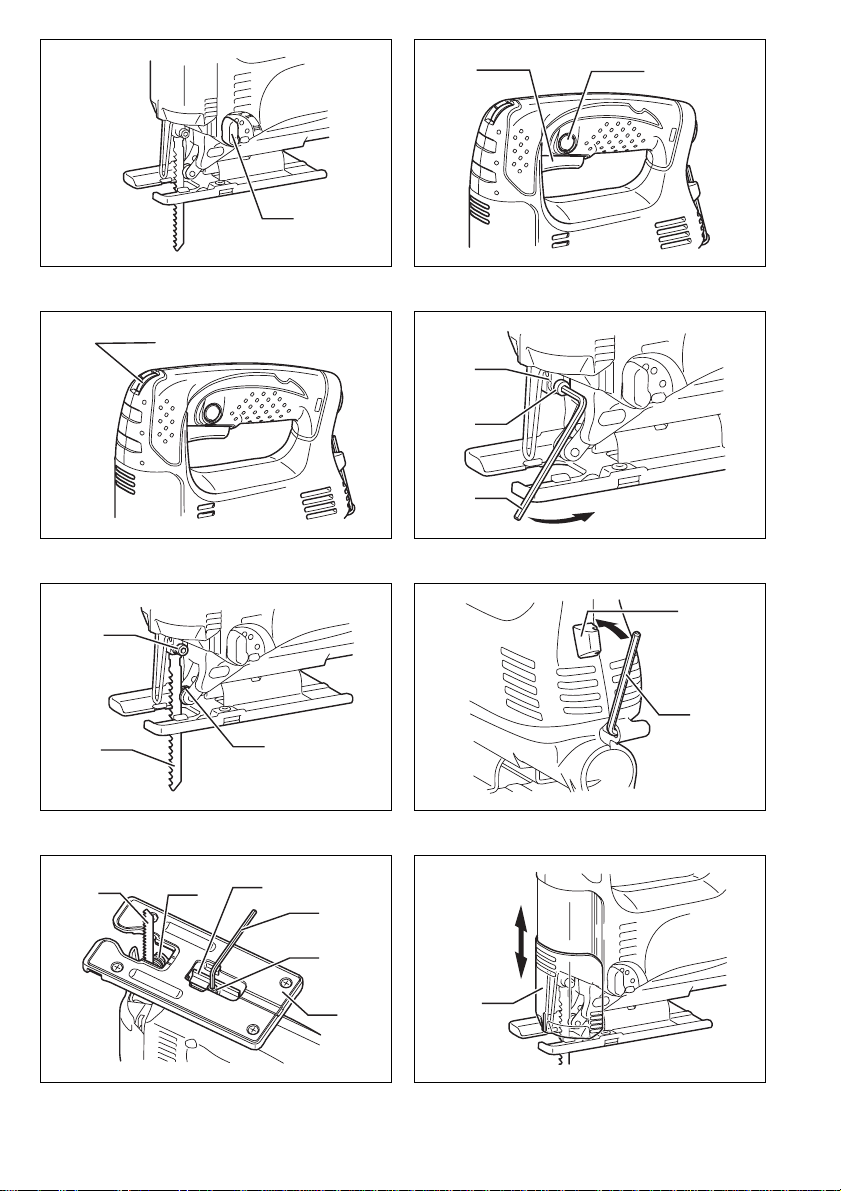
Switch action (Fig. 2)
CAUTION:
• Before plugging in the tool , always check to see that
the switch trigger actu ates properly a nd returns to the
“OFF” position when released.
To start the tool, simply pull the switch trigg er. Release
the switch trigger to stop.
For continuous operation, pull the switch trigger and then
push in the lock button.
To stop the tool from the locked position, pull the switch
trigger fully, then release it.
Speed adjusting dial (F or models 4327/432 8/4329)
(Fig. 3)
The tool speed can be inf initely adjusted between 500
and 3,100 strokes per minute by turning the adjusting
dial. Higher speed is ob tained when th e dial is turn ed in
the direction of number 6; lower speed is obtained when
it is turned in the direction of number 1.
Refer to the table to select the proper speed for the workpiece to be cut. However, the appropriate sp eed m ay differ with the type or thickness of the workpiece. In
general, higher speeds w ill allow you to cut workpieces
faster but the service life of the blade will be reduced.
For cutting mild steel, stainless steel and plastics.
For clean cuts in wood and plywood.
For cutting wood and plywood.
For fast cutting in aluminum and mild steel.
Wor kpiece to be cut Number on adjusting dial
Wood 5 – 6
Mild steel 3 – 6
Stainless steel 3 – 4
Aluminum 3 – 6
Plastics 1 – 4
CAUTION:
• If the tool is o perated con tinuously at l ow speeds for a
long time, the motor will get overloaded and heated up.
• The speed adjusting dial can be turned only as far as 6
and back to 1. Do not force i t past 6 or 1, or the speed
adjusting function may no longer work.
ASSEMBLY
CAUTION:
• Always be sure that the tool is switched off and
unplugged before carrying out any work on the tool.
Installing or r em ovi ng saw blade (Fig. 4 & 5)
CAUTION:
• Always clean out all chips or foreign matter adh er in g to
the blade and/or blade holder. Failure to do so may
cause insufficient tighte ning of the blad e, resulting in a
serious personal injury.
9

• Do not touch th e blade or the workpiece immedi ately
after operation; they may be extremely h ot and could
burn your skin.
• Alway s se c ur e the blade firmly. In s uff i c ie nt t igh t en i ng of
the blade may cause blade bre akage or serious personal injury.
• Use only B type blades. Using blades other than B type
blades causes insufficient tightening of the blade,
resulting in a serious personal injury.
To install the blade, lo osen the bo lt counterclockwis e on
the blade holder with the hex wrench.
With the blade teeth facing forward, insert the blade into
the blade holder as far as it will go. Make sure that the
back edge of the blade fits into the roller. Then tighten the
bolt clockwise to secure the blade.
To remove the blade, follow the installation procedure in
reverse.
NOTE:
• Occasionally lubricate the roller.
Hex wrench storage (Fig . 6)
When not in use, store the h ex wrench as shown in the
figure to keep it from being lost.
Adjusting roller (For models 4326/4327) (Fig.7)
Loosen the bolt on th e ba ck of the too l base w ith the hex
wrench. Move the retai ner so t hat the roller c ontacts the
blade lightly. Then tighten the bolt to secure the tool base
and the retainer.
NOTE:
• Occasionally lubricate the roller.
Dust cover (Fig.8)
CAUTION:
• Always wear safety goggles even when operating the
tool with the dust cover lowered.
Lower the dust cover to prevent chips from flying. However, when making bevel cuts, raise it all the way.
OPERATION
CAUTION:
• Always hold the base flush with the wor kpiece. Failure
to do so may cause blade breakage, resulting in a ser i ous injury.
• Advance the tool very slowly w hen cutting curves or
scrolling. Forcing the tool may cause a slanted cutting
surface and blade breakage.
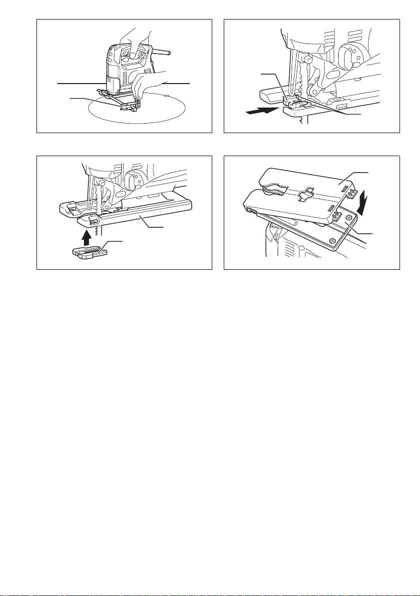
Turn the tool on without the blade making any contact
and wait until the blade attains ful l speed. Then rest the
tool base flat on the w orkpiece and gentl y move the tool
forward along the previously marked cutting line. (Fig. 9)
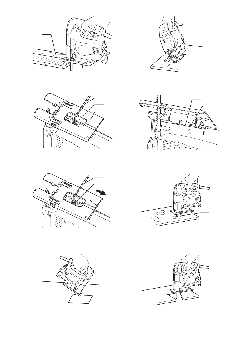
Bevel cutting
CAUTION:
• Always be sure that the tool is switched off and
unplugged before tilting the tool base.
• Raise the dust cover all the way before making bevel
cuts.
With the base tilted, you can make bevel cuts at any
angle between 0° and 45° (left or right). (Fig. 10)
Loosen the bolt on t he back of the base with the hex
wrench. Move the tool base so that the bolt is positioned
in the center of the cross-shaped slot in the base.
(Fig. 11)
Tilt the base until the desired bevel angle is obtained.
The edge of the moto r housi ng in dicates th e bevel angle
by graduations. Then tig hte n the bo lt to secure the b ase.
(Fig. 12)
Front flush cuts (Fig. 13)
Loosen the bolt on the back of the tool base with the hex
wrench, and slide the base all the way back. Then tighten
the bolt to secure the tool base.
Cutouts
Cutouts can be made with either of two methods A or B.
A) Boring a starting hole
For internal cutouts without a lead-in cut from an
edge, pre-drill a starting hole 12 mm or more in diameter. Insert the blade int o this hole to star t your cut.
(Fig. 14)
B) Plunge cutting
You need not bore a starting h ole or make a lead- in
cut if you carefully do as follows.
1. Tilt the tool up on the front edge of th e base with
the blade point positioned just above the workpiece surface. (Fig. 15)
2. Apply pressure to the tool so that the fron t ed ge o f
the base will not move when you switch on the tool
and gently lower the back end of the tool slowly.
3. As the blade pierces the workpiece, slowly lower
the base of the tool d own ont o the workp iece surface.
4. Complete the cut in the normal manner.
Finishing edges (Fig. 16)
To trim edges or make dimensional adjustments, run the
blade lightly along the cut edges.
Metal cutting
Always use a suitable coolant (cutting oil) when cutting
metal. Failure to do so will cause significant blade wear.
The underside of th e workpiece c an be greased ins tead
of using a coolant.
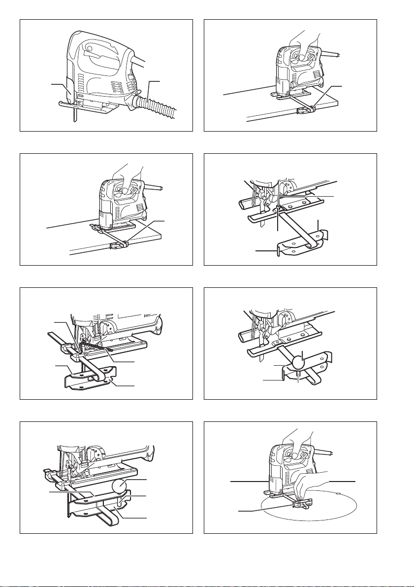
Dust extraction (Fig.17)
Clean cutting operations can be performed by connecting
this tool to a Makita vacuum cleaner. Insert the hose of
the vacuum cleaner int o the hole at the r ear of the tool.
Lower the dust cover before operation.
NOTE:
• Dust extraction cannot be performed when making
bevel cuts.
Rip fence (optional ac cessory)
CAUTION:
• Always be sure that the tool is switched off and
unplugged before installing or removing accessories.
1) Straight cuts (Fig. 18, 19, 20 & 21)
When repeatedly cut ting widths of 160 mm or less,
use of the rip fence will assure fast, clean, straight
cuts.
To install, insert the rip fence into the rectangular hole
on the side of the tool base with the fence guide facing down. Slide the rip fence to the desir ed cutting
width position, then tighten the bolt to secure it.
10
 Loading...