

Page 1
INSTRUCTION MANUAL
MANUEL D'INSTRUCTION
MANUAL DE INSTRUCCIONES
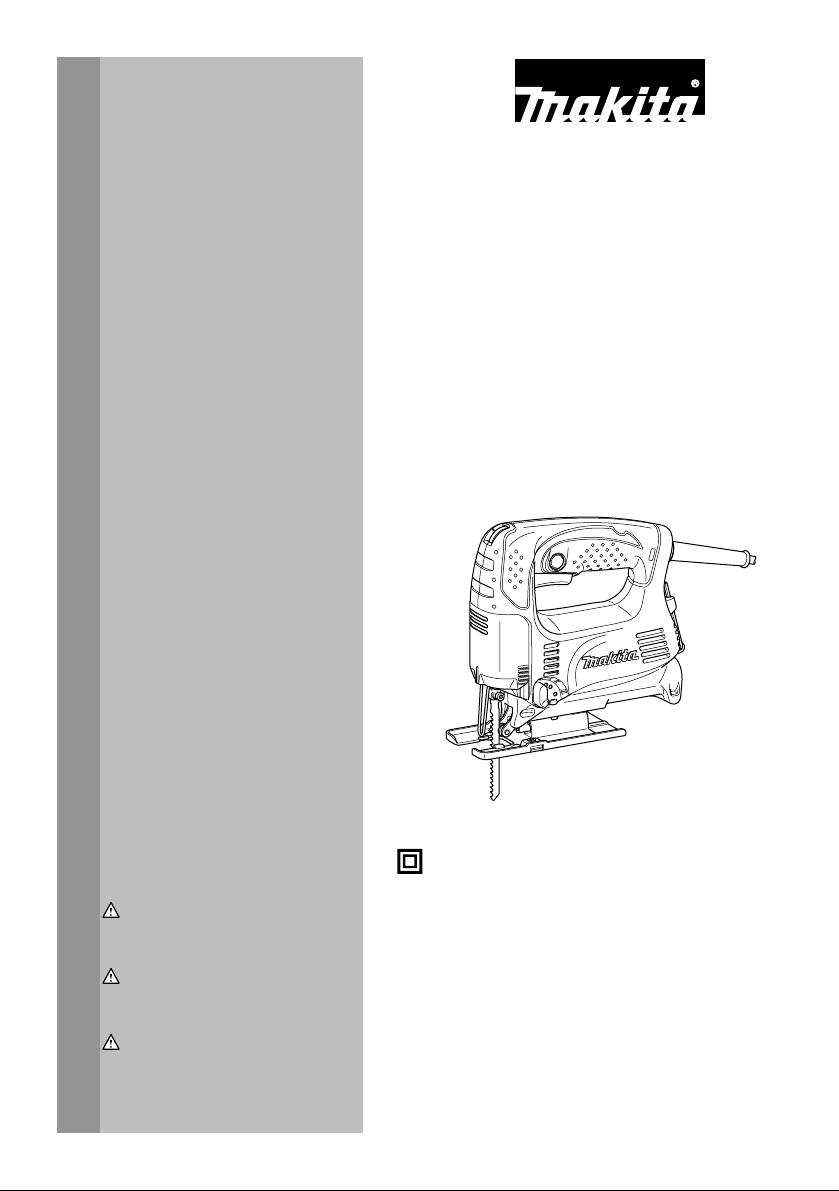
Jig Saw
Scie sauteuse
Sierra Caladora
4326
4327
4328
4329
008081
DOUBLE INSULATION
DOUBLE ISOLATION
WARNING:
For your personal safety, READ and UNDERSTAND before using.
SAVE THESE INSTRUCTIONS FOR FUTURE REFERENCE.
AVERTISSEMENT:
Pour votre propre sécurité, prière de lire attentivement avant l'utilisation.
GARDER CES INSTRUCTIONS POUR RÉFÉRENCE ULTÉRIEURE.
ADVERTENCIA:
Para su seguridad personal, LEA DETENIDAMENTE este manual antes de usar la
herramienta.
GUARDE ESTAS INSTRUCCIONES PARA FUTURA REFERENCIA.
DOBLE AISLAMIENTO
1
Page 2

ENGLISH
SPECIFICATIONS
Model 4326 4327 4328 4329
Length of stroke 18 mm (11/16") 18 mm (11/16") 18 mm (11/16") 18 mm (11/16")
Max. cutting
capacities
Strokes per minute 3,100/min 500 - 3,100/min 500 - 3,100/min 500 - 3,100/min
Overall length
Net weight
• Due to our continuing programme of research and development, the specifications herein are subject to change without notice.
• Note: Specifications may differ from country to country.
GENERAL SAFETY RULES
WARNING! Read all instructions. Failure to follow all
instructions listed below may result in electric shock, fire
and/or serious injury. The term "power tool" in all of the
warnings listed below refers to your mains-operated
(corded) power tool or battery-operated (cordless) power
tool.
SAVE THESE INSTRUCTIONS.
Work area safety
1. Keep work area clean and well lit. Cluttered and
dark areas invite accidents.
2. Do not operate power tools in explosive
atmospheres, such as in the presence of
flammable liquids, gases or dust. Power tools
create sparks which may ignite the dust or fumes.
3. Keep children and bystanders away while
operating a power tool. Distractions can cause
you to lose control.
Electrical Safety
4. Power tool plugs must match the outlet. Never
modify the plug in any way. Do not use any
adapter plugs with earthed (grounded) power
tools. Unmodified plugs and matching outlets will
reduce risk of electric shock.
5. Avoid body contact with earthed or grounded
surfaces such as pipes, radiators, ranges and
refrigerators. There is an increased risk of
electric shock if your body is earthed or grounded.
6. Do not expose power tools to rain or wet
conditions. Water entering a power tool will
increase the risk of electric shock.
7. Do not abuse the cord. Never use the cord for
Wood 65 mm (2-9/16") 65 mm (2-9/16") 65 mm (2-9/16") 65 mm (2-9/16")
Mild steel 6 mm (1/4") 6 mm (1/4") 6 mm (1/4") 6 mm (1/4")
217 mm (8-1/2") 217 mm (8-1/2")
(Steel base type) (Steel base type)
223 mm (8-3/4") 223 mm (8-3/4")
(Aluminum base type) (Aluminum base type)
1.8 kg (4.0 lbs) 1.8 kg (4.0 lbs)
(Steel base type) (Steel base type)
1.9 kg (4.2 lbs) 1.9 kg (4.2 lbs)
(Aluminum base type) (Aluminum base type)
GEA001-3
carrying, pulling or unplugging the power tool.
217 mm (8-1/2") 223 mm (8-3/4")
1.8 kg (4.0 lbs) 1.9 kg (4.2 lbs)
Keep cord away from heat, oil, sharp edges or
moving parts. Damaged or entangled cords
increase the risk of electric shock.
8. When operating a power tool outdoors, use an
extension cord suitable for outdoor use. Use of
a cord suitable for outdoor use reduces the risk of
electric shock.
Personal Safety
9. Stay alert, watch what you are doing and use
common sense when operating a power tool.
Do not use a power tool while you are tired or
under the influence of drugs, alcohol or
medication. A moment of inattention while
operating power tools may result in serious
personal injury.
10. Use safety equipment. Always wear eye
protection. Safety equipment such as dust mask,
non-skid safety shoes, hard hat, or hearing
protection used for appropriate conditions will
reduce personal injuries.
11. Avoid accidental starting. Ensure the switch is
in the off-position before plugging in. Carrying
power tools with your finger on the switch or
plugging in power tools that have the switch on
invites accidents.
12. Remove any adjusting key or wrench before
turning the power tool on. A wrench or a key left
attached to a rotating part of the power tool may
result in personal injury.
13. Do not overreach. Keep proper footing and
balance at all times. This enables better control
of the power tool in unexpected situations.
14. Dress properly. Do not wear loose clothing or
jewellery. Keep your hair, clothing, and gloves
2
Page 3

away from moving parts. Loose clothes,
jewellery or long hair can be caught in moving
parts.
15. If devices are provided for the connection of
dust extraction and collection facilities,
ensure these are connected and properly used.
Use of these devices can reduce dust-related
hazards.
Power tool use and care
16. Do not force the power tool. Use the correct
power tool for your application. The correct
power tool will do the job better and safer at the
rate for which it was designed.
17. Do not use the power tool if the switch does
not turn it on and off. Any power tool that cannot
be controlled with the switch is dangerous and
must be repaired.
18. Disconnect the plug from the power source
and/or the battery pack from the power tool
before making any adjustments, changing
accessories, or storing power tools. Such
preventive safety measures reduce the risk of
starting the power tool accidentally.
19. Store idle power tools out of the reach of
children and do not allow persons unfamiliar
with the power tool or these instructions to
operate the power tool. Power tools are
dangerous in the hands of untrained users.
20. Maintain power tools. Check for misalignment
or binding of moving parts, breakage of parts
and any other condition that may affect the
power tools operation. If damaged, have the
power tool repaired before use. Many accidents
are caused by poorly maintained power tools.
21. Keep cutting tools sharp and clean. Properly
maintained cutting tools with sharp cutting edges
are less likely to bind and are easier to control.
22. Use the power tool, accessories and tool bits
etc. in accordance with these instructions and
in the manner intended for the particular type
of power tool, taking into account the working
conditions and the work to be performed. Use
of the power tool for operations different from
those intended could result in a hazardous
situation.
SERVICE
23. Have your power tool serviced by a qualified
repair person using only identical replacement
parts. This will ensure that the safety of the power
tool is maintained.
24. Follow instruction for lubricating and
changing accessories.
25. Keep handles dry, clean and free from oil and
grease.
SPECIFIC SAFETY RULES
DO NOT let comfort or familiarity with product
(gained from repeated use) replace strict adherence
to jig saw safety rules. If you use this tool unsafely
or incorrectly, you can suffer serious personal
injury.
1. Hold power tools by insulated gripping
surfaces when performing an operation where
the cutting tool may contact hidden wiring or
its own cord. Contact with a "live" wire will make
exposed metal parts of the tool "live" and shock
the operator.
2. Use clamps or another practical way to secure
and support the workpiece to a stable platform.
Holding the work by hand or against your body
leaves it unstable and may lead to loss of control.
3. Always use safety glasses or goggles.
Ordinary eye or sun glasses are NOT safety
glasses.
4. Avoid cutting nails. Inspect workpiece for any
nails and remove them before operation.
5. Do not cut oversize workpiece.
6. Check for the proper clearance beyond the
workpiece before cutting so that the blade will
not strike the floor, workbench, etc.
7. Hold the tool firmly.
8. Make sure the blade is not contacting the
workpiece before the switch is turned on.
9. Keep hands away from moving parts.
10. Do not leave the tool running. Operate the tool
only when hand-held.
11. Always switch off and wait for the blade to
come to a complete stop before removing the
blade from the workpiece.
12. Do not touch the blade or the workpiece
immediately after operation; they may be
extremely hot and could burn your skin.
13. Do not operate the tool at no-load
unnecessarily.
14. Some material contains chemicals which may
be toxic. Take caution to prevent dust
inhalation and skin contact. Follow material
supplier safety data.
15. Always use the correct dust mask/respirator
for the material and application you are
working with.
SAVE THESE INSTRUCTIONS.
WARNING:
MISUSE or failure to follow the safety rules stated in
this instruction manual may cause serious personal
GEB016-1
3
Page 4
injury.
USD201-2
Symbols
The followings show the symbols used for tool.
・ volts
・ amperes
・ hertz
・ alternating current
・ no load speed
・ Class II Construction
・ revolutions or reciprocation per minute
FUNCTIONAL DESCRIPTION
CAUTION:
• Always be sure that the tool is switched off and
unplugged before adjusting or checking function on
the tool.
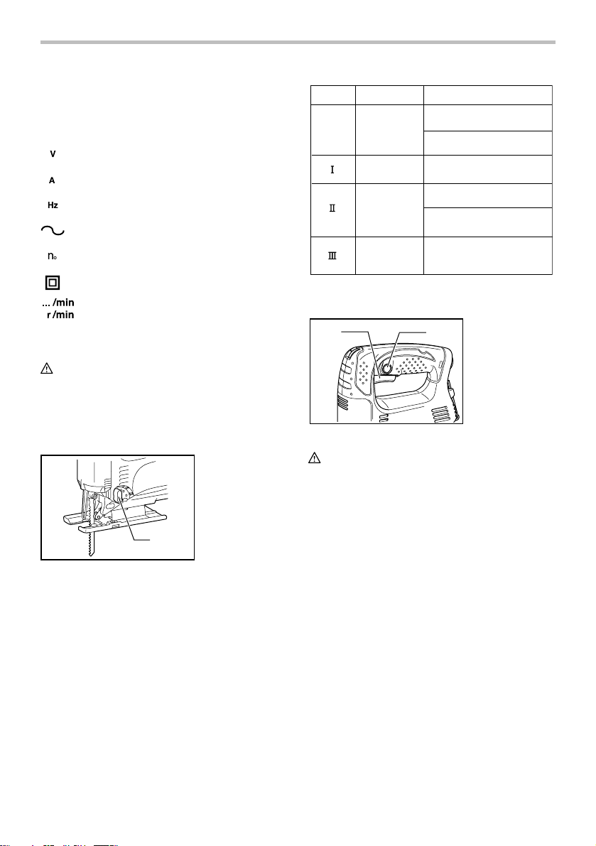
Selecting the cutting action (For models
4328/4329)
1. Cutting action
changing lever
1
008153
This tool can be operated with an orbital or a straight line
(up and down) cutting action. The orbital cutting action
thrusts the blade forward on the cutting stroke and
greatly increases cutting speed.
To change the cutting action, just turn the cutting action
changing lever to the desired cutting action position.
Refer to the table to select the appropriate cutting action.
Position
006582
0
Cutting action
Straight line
cutting action
Small orbit
cutting action
Medium orbit
cutting action
Large orbit
cutting action
Applications
For cutting mild steel,
stainless steel and plastics.
For clean cuts in wood
and plywood.
For cutting mild steel,
aluminum and hard wood.
For cutting wood and
plywood.
For fast cutting in aluminum
and mild steel.
For fast cutting in wood
and plywood.
Switch action
1
008082
2
CAUTION:
• Before plugging in the tool, always check to see
that the switch trigger actuates properly and
returns to the "OFF" position when released.
• Switch can be locked in "ON" position for ease of
operator comfort during extended use. Apply
caution when locking tool in "ON" position and
maintain firm grasp on tool.
To start the tool, simply pull the switch trigger. Release
the switch trigger to stop.
For continuous operation, pull the switch trigger and
then push in the lock button.
To stop the tool from the locked position, pull the switch
trigger fully, then release it.
1. Switch trigger
2. Lock button
4
Page 5
Speed adjusting dial (For models
4327/4328/4329)
1
008167
The tool speed can be infinitely adjusted between 500
and 3,100 strokes per minute by turning the adjusting
dial. Higher speed is obtained when the dial is turned in
the direction of number 6; lower speed is obtained when
it is turned in the direction of number 1.
Refer to the table to select the proper speed for the
workpiece to be cut. However, the appropriate speed
may differ with the type or thickness of the workpiece. In
general, higher speeds will allow you to cut workpieces
faster but the service life of the blade will be reduced.
Workpiece to be cut Number on adjusting dial
Wood 5 - 6
Mild steel3 - 6
Stainless steel3 - 4
Aluminum 3 - 6
006583
Plastics
CAUTION:
• If the tool is operated continuously at low speeds
for a long time, the motor will get overloaded and
heated up.
• The speed adjusting dial can be turned only as far
as 6 and back to 1. Do not force it past 6 or 1, or
the speed adjusting function may no longer work.
1. Speed adjusting
dial
1 - 4
ASSEMBLY
CAUTION:
• Always be sure that the tool is switched off and
unplugged before carrying out any work on the
tool.
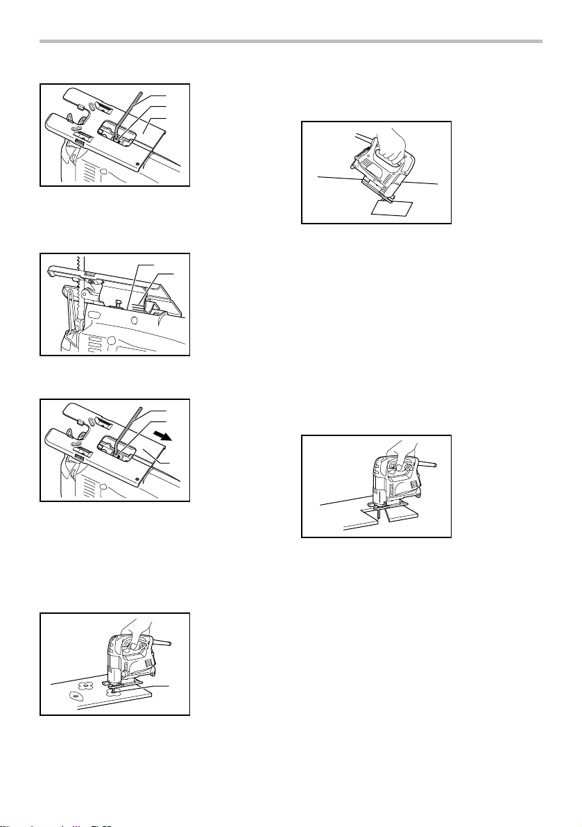
Installing or removing saw blade
1. Blade holder
1
2. Bolt
3. Hex wrench
2
3
008083
CAUTION:
• Always clean out all chips or foreign matter
adhering to the blade and/or blade holder. Failure
to do so may cause insufficient tightening of the
blade, resulting in a serious personal injury.
• Do not touch the blade or the workpiece
immediately after operation; they may be
extremely hot and could burn your skin.
• Always secure the blade firmly. Insufficient
tightening of the blade may cause blade breakage
or serious personal injury.
• Use only B type blades. Using blades other than B
type blades causes insufficient tightening of the
blade, resulting in a serious personal injury.
To install the blade, loosen the bolt counterclockwise on
the blade holder with the hex wrench.
With the blade teeth facing forward, insert the blade into
the blade holder as far as it will go. Make sure that the
back edge of the blade fits into the roller. Then tighten
the bolt clockwise to secure the blade.
1. Bolt
2. Blade
3. Roller
008084
1
2
3
To remove the blade, follow the installation procedure in
reverse.
NOTE:
• Occasionally lubricate the roller.
5
Page 6
Hex wrench storage
1. Hook
1
2. Hex wrench
2
008085
When not in use, store the hex wrench as shown in the
figure to keep it from being lost.
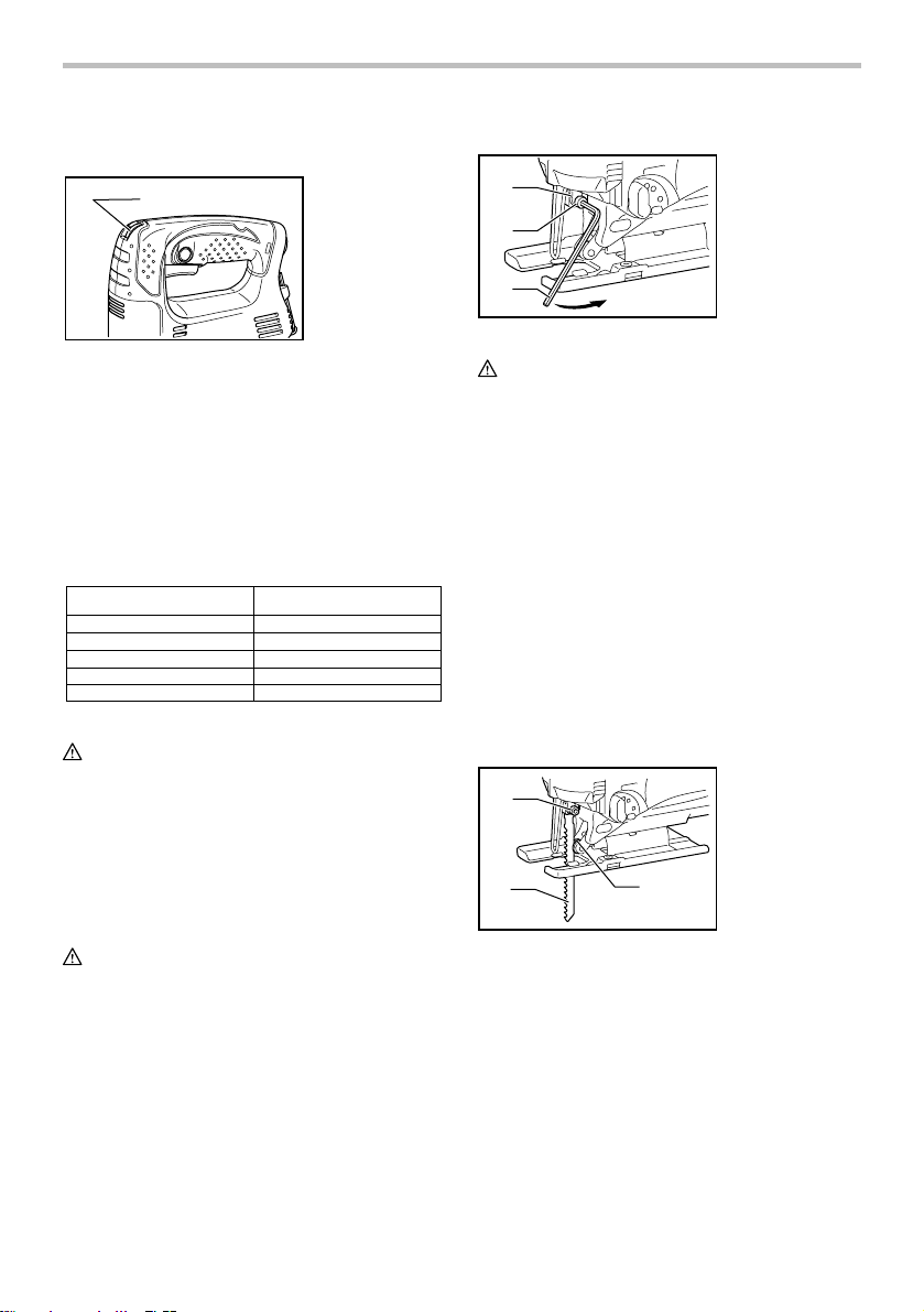
Adjusting roller (For models 4326/4327)
3
1
008154
Loosen the bolt on the back of the base with the hex
wrench. Move the retainer so that the roller contacts the
blade lightly. Then tighten the bolt to secure the base
and the retainer.
NOTE:
• Occasionally lubricate the roller.
2
1. Blade
2. Roller
4
3. Retainer
4. Hex wrench
5
5. Bolt
6. Base
6
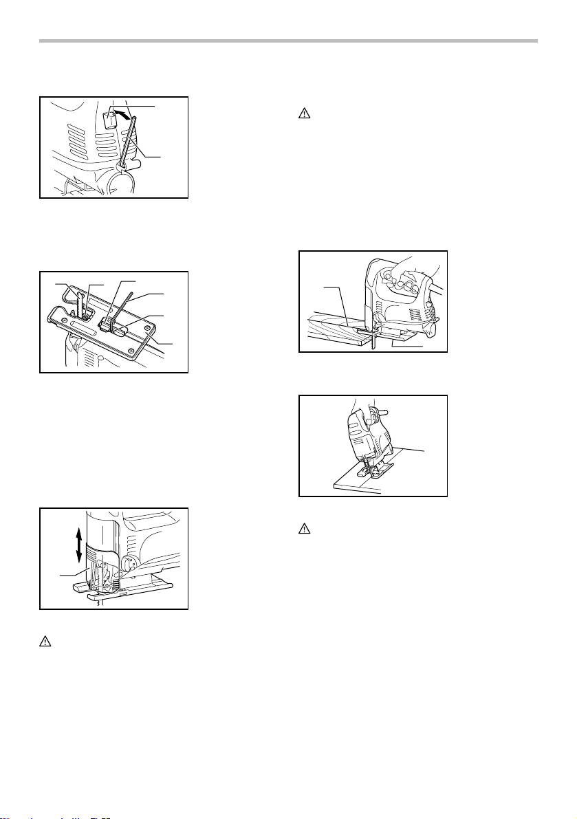
Dust cover
1. Dust cover
1
008086
CAUTION:
• Always wear safety goggles even when operating
the tool with the dust cover lowered.
Lower the dust cover to prevent chips from flying.
However, when making bevel cuts, raise it all the way.
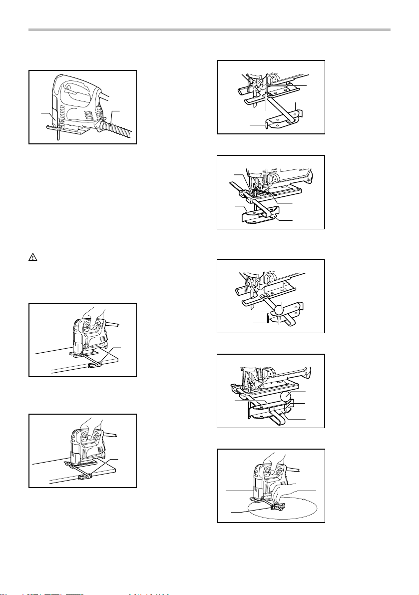
OPERATION
CAUTION:
• Always hold the base flush with the workpiece.
Failure to do so may cause blade breakage,
resulting in a serious injury.
• Advance the tool very slowly when cutting curves
or scrolling. Forcing the tool may cause a slanted
cutting surface and blade breakage.
Turn the tool on without the blade making any contact
and wait until the blade attains full speed. Then rest the
base flat on the workpiece and gently move the tool
forward along the previously marked cutting line.
1. Cutting line
2. Base
1
2
008087
Bevel cutting
008088
CAUTION:
• Always be sure that the tool is switched off and
unplugged before tilting the base.
• Raise the dust cover all the way before making
bevel cuts.
With the base tilted, you can make bevel cuts at any
angle between 0° and 45° (left or right).
Loosen the bolt on the back of the base with the hex
wrench. Move the base so that the bolt is positioned in
the center of the cross-shaped slot in the base.
6
Page 7
1
2
3
1. Hex wrench
2. Bolt
3. Base
diameter. Insert the blade into this hole to start your
cut.
B) Plunge cutting
008089
Tilt the base until the desired bevel angle is obtained.
The edge of the motor housing indicates the bevel angle
by graduations. Then tighten the bolt to secure the base.
008090
1. Edge
1
2. Graduation
2
Front flush cuts
1. Hex wrench
1
2. Bolt
2
3. Base
3
008091
Loosen the bolt on the back of the base with the hex
wrench and slide the base all the way back. Then tighten
the bolt to secure the base.
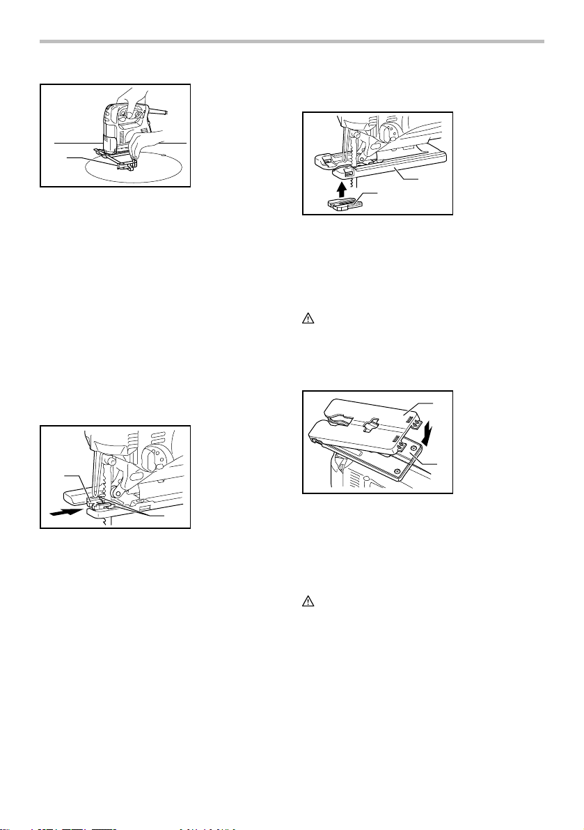
Cutouts
Cutouts can be made with either of two methods A or B.
A) Boring a starting hole
1. Starting hole
1
008092
For internal cutouts without a lead-in cut from an
edge, pre-drill a starting hole 12 mm or more in
008093
You need not bore a starting hole or make a lead-in
cut if you carefully do as follows.
(1) Tilt the tool up on the front edge of the base
with the blade point positioned just above the
workpiece surface.
(2) Apply pressure to the tool so that the front
edge of the base will not move when you
switch on the tool and gently lower the back
end of the tool slowly.
(3) As the blade pierces the workpiece, slowly
lower the base of the tool down onto the
workpiece surface.
(4) Complete the cut in the normal manner.
Finishing edges
008094
To trim edges or make dimensional adjustments, run the
blade lightly along the cut edges.
Metal cutting
Always use a suitable coolant (cutting oil) when cutting
metal. Failure to do so will cause significant blade wear.
The underside of the workpiece can be greased instead
of using a coolant.
7
Page 8
Dust extraction
1. Dust cover
2. Hose
1
008095
Clean cutting operations can be performed by
connecting this tool to a Makita vacuum cleaner. Insert
the hose of the vacuum cleaner into the hole at the rear
of the tool. Lower the dust cover before operation.
NOTE:
• Dust extraction cannot be performed when making
bevel cuts.
Rip fence (optional accessory)
CAUTION:
• Always be sure that the tool is switched off and
unplugged before installing or removing
accessories.
1. Straight cuts
Steel base type
008096
When repeatedly cutting widths of 160 mm or less,
use of the rip fence will assure fast, clean, straight
cuts.
Aluminum base type
2
1. Rip fence (Guide
rule)
1
1. Rip fence (Guide
rule)
1
Steel base type
2
3
002776
Aluminum base type
1
2
005454
2. Circular cuts
Steel base type
2
3
002777
Aluminum base type
4
005455
Steel base type
1. Hex wrench
2. Bolt
3. Rip fence (Guide
1
rule)
4
4. Guide facing
1. Bolt
2. Fence guide
3. Hex wrench
4. Rip fence (Guide
rule)
3
4
1
4
1. Treaded knob
2. Guide facing
3. Rip fence (Guide
rule)
4. Pin
1. Threaded knob
2. Pin
3. Rip fence (Guide
rule)
4. Fence guide
1
2
3
1. Rip fence (Guide
rule)
008097
To install, insert the rip fence into the rectangular
hole on the side of the base with the fence guide
facing down. Slide the rip fence to the desired
cutting width position, then tighten the bolt to
secure it.
8
1
008098
Page 9
Aluminum base type
1
008099
When cutting circles or arcs of 170 mm or less in
radius, install the rip fence as follows.
Insert the rip fence into the rectangular hole on the
side of the base with the fence guide facing up.
Insert the circular guide pin through either of the
two holes on the fence guide. Screw the threaded
knob onto the pin to secure the pin.
Now slide the rip fence to the desired cutting radius,
and tighten the bolt to secure it in place. Then
move the base all the way forward.
NOTE:
• Always use blades No. B-17, B-18, B-26 or B-27
when cutting circles or arcs.
1. Rip fence (Guide
rule)
Anti-splintering device for steel base
(optional accessory)
1. Anti-splintering
device
2. Protrusions
1
2
008100
For splinter-free cuts, the anti-splintering device can be
used. To install the anti-splintering device, move the
base all the way forward and insert it between the two
protrusions of the base.
NOTE:
• The anti-splintering device cannot be used when
making bevel cuts.
Anti-splintering device for aluminum base
(Optional accessory)
1. Anti-splintering
device
2. Aluminum base
1
008101
For splinter-free cuts, the anti-splintering device can be
used. To install the anti-splintering device, move the tool
base all the way forward and fit it from the back of tool
base. When you use the cover plate, install the
anti-splintering device onto the cover plate.
CAUTION:
• The anti-splintering device cannot be used when
making bevel cuts.
2
Cover plate for aluminum base (Optional
accessory)
1. Cover plate
1
2. Aluminum base
2
008102
Use the cover plate when cutting decorative veneers,
plastics, etc. It protects sensitive or delicate surfaces
from damage. Fit it on the back of the tool base.
MAINTENANCE
CAUTION:
• Always be sure that the tool is switched off and
unplugged before attempting to perform inspection
or maintenance.
To maintain product SAFETY and RELIABILITY, repairs,
carbon brush inspection and replacement, any other
maintenance or adjustment should be performed by
Makita Authorized Service Centers, always using Makita
replacement parts.
9
Page 10

ACCESSORIES
CAUTION:
• These accessories or attachments are
recommended for use with your Makita tool
specified in this manual. The use of any other
accessories or attachments might present a risk of
injury to persons. Only use accessory or
attachment for its stated purpose.
If you need any assistance for more details regarding
these accessories, ask your local Makita Service Center.
• Jig saw blades
• Hex wrench 3
• Rip fence (guide rule) set
• Anti-splintering device
• Hose (For vacuum cleaner)
• Cover plate (For aluminum base type)
MAKITA LIMITED ONE YEAR WARRANTY
Warranty Policy
Every Makita tool is thoroughly inspected and tested
before leaving the factory. It is warranted to be free of
defects from workmanship and materials for the period
of ONE YEAR from the date of original purchase.
Should any trouble develop during this one year period,
return the COMPLETE tool, freight prepaid, to one of
Makita’s Factory or Authorized Service Centers. If
inspection shows the trouble is caused by defective
workmanship or material, Makita will repair (or at our
option, replace) without charge.
This Warranty does not apply where:
repairs have been made or attempted by others:
repairs are required because of normal wear and
tear:
the tool has been abused, misused or improperly
maintained:
alterations have been made to the tool.
IN NO EVENT SHALL MAKITA BE LIABLE FOR ANY
INDIRECT, INCIDENTAL OR CONSEQUENTIAL
DAMAGES FROM THE SALE OR USE OF THE
PRODUCT. THIS DISCLAIMER APPLIES BOTH
DURING AND AFTER THE TERM OF THIS
WARRANTY.
MAKITA DISCLAIMS LIABILITY FOR ANY IMPLIED
WARRANTIES, INCLUDING IMPLIED WARRANTIES
OF "MERCHANTABILITY" AND "FITNESS FOR A
SPECIFIC PURPOSE," AFTER THE ONE YEAR TERM
OF THIS WARRANTY.
This Warranty gives you specific legal rights, and you
may also have other rights which vary from state to
state. Some states do not allow the exclusion or
limitation of incidental or consequential damages, so
the above limitation or exclusion may not apply to you.
Some states do not allow limitation on how long an
implied warranty lasts, so the above limitation may not
apply to you.
EN0006-1
10
Page 11

FRANÇAIS
SPÉCIFICATIONS
Modèle 4326 4327 4328 4329
Longueur de frappe 18 mm (11/16") 18 mm (11/16") 18 mm (11/16") 18 mm (11/16")
Capacités de
coupe max.
Nombre d'impacts par minutes 3,100/min 500 - 3,100/min 500 - 3,100/min 500 - 3,100/min
Longueur totale
Poids net
• Étant donné l'évolution constante de notre programme de recherche et de développement, les spécifications contenues dans ce
manuel sont sujettes à modification sans préavis.
• Note : Les spécifications peuvent varier suivant les pays.
Règles de sécurité générales
AVERTISSEMENT! Veuillez lire l'ensemble des
présentes instructions. Il y a risque de choc électrique,
d'incendie et/ou de blessure grave si toutes les
instructions énumérées ci-dessous ne sont pas
respectées. Le terme ≪outil électrique≫ qui figure sur
tous les avertissements énumérés ci-dessous fait
référence à un outil électrique branché sur une prise de
courant (par un cordon d'alimentation) ou alimenté par
batterie (sans fil).
CONSERVEZ CE MODE
D'EMPLOI.
Sécurité de la zone de travail
1. Maintenez la zone de travail propre et bien
éclairée. Les zones de travail encombrées et
sombres ouvrent grande la porte aux accidents.
2. N'utilisez pas les outils électriques dans les
atmosphères explosives, par exemple en
présence de liquides, gaz ou poussières
inflammables. Les outils électriques produisent
des étincelles au contact desquelles la poussière
ou les vapeurs peuvent s'enflammer.
3. Assurez-vous qu'aucun enfant ou curieux ne
s'approche pendant que vous utilisez un outil
électrique. Vous risquez de perdre la maîtrise de
l'outil si votre attention est détournée.
Sécurité en matière d'électricité
4. Les fiches d'outil électrique sont conçues
pour s'adapter parfaitement aux prises de
courant. Ne modifiez jamais la fiche de
Bois 65 mm (2-9/16") 65 mm (2-9/16") 65 mm (2-9/16") 65 mm (2-9/16")
Acier doux 6 mm (1/4") 6 mm (1/4") 6 mm (1/4") 6 mm (1/4")
217 mm (8-1/2") 217 mm (8-1/2")
(Avec base d'acier) (Avec base d'acier)
223 mm (8-3/4") 223 mm (8-3/4")
(Type de base en aluminium) (Type de base en aluminium)
1.8 kg (4.0 lbs) 1.8 kg (4.0 lbs)
(Avec base d'acier) (Avec base d'acier)
1.9 kg (4.2 lbs) 1.9 kg (4.2 lbs)
(Type de base en aluminium) (Type de base en aluminium)
GEA001-3
quelque façon que ce soit. N'utilisez aucun
217 mm (8-1/2") 223 mm (8-3/4")
1.8 kg (4.0 lbs) 1.9 kg (4.2 lbs)
adaptateur de fiche sur les outils électriques
avec mise à la terre. En ne modifiant pas les
fiches et en les insérant dans des prises de
courant pour lesquelles elles ont été conçues
vous réduirez les risques de choc électrique.
5. Évitez tout contact corporel avec les surfaces
mises à la terre, telles que les tuyaux,
radiateurs, cuisinières et réfrigérateurs. Le
risque de choc électrique est plus élevé si votre
corps se trouve mis à la terre.
6. N'exposez pas les outils électriques à la pluie
ou à l'eau. La présence d'eau dans un outil
électrique augmente le risque de choc électrique.
7. Ne maltraitez pas le cordon. N'utilisez jamais
le cordon pour transporter, tirer ou débrancher
l'outil électrique. Maintenez le cordon à l'écart
des sources de chaleur, de l'huile, des objets à
bords tranchants et des pièces en mouvement.
Le risque de choc électrique est plus élevé
lorsque les cordons sont endommagés ou
enchevêtrés.
8. Lorsque vous utilisez un outil électrique à
l'extérieur, utilisez un cordon prolongateur
prévu à cette fin. Les risques de choc électrique
sont moindres lorsqu'un cordon conçu pour
l'extérieur est utilisé.
Sécurité personnelle
9. Restez alerte, attentif à vos mouvements et
faites preuve de bon sens lorsque vous
utilisez un outil électrique. Évitez d'utiliser un
outil électrique si vous êtes fatigué ou si vous
avez pris une drogue, de l'alcool ou un
médicament. Un moment d'inattention pendant
11
Page 12

l'utilisation d'un outil électrique peut entraîner une
grave blessure.
10. Utilisez des dispositifs de sécurité. Portez
toujours un protecteur pour la vue. Les risques
de blessure seront moins élevés si vous utilisez
des dispositifs de sécurité tels qu'un masque
antipoussières, des chaussures à semelle
antidérapante, une coiffure résistante ou une
protection d'oreilles.
11. Prévenez tout démarrage accidentel.
Assurez-vous que l'interrupteur est en
position d'arrêt avant de brancher l'outil. Vous
ouvrez la porte aux accidents si vous transportez
les outils électriques avec le doigt sur
l'interrupteur ou les branchez alors que
l'interrupteur est en position de marche.
12. Retirez toute clé de réglage ou de serrage
avant de mettre l'outil sous tension. Toute clé
laissée en place sur une pièce rotative de l'outil
électrique peut entraîner une blessure.
13. Maintenez une bonne position. Assurez-vous
d'une bonne prise au sol et d'une bonne
position d'équilibre en tout temps. Cela vous
permettra d'avoir une meilleure maîtrise de l'outil
dans les situations imprévues.
14. Portez des vêtements adéquats. Ne portez ni
vêtements amples ni bijoux. Vous devez
maintenir cheveux, vêtements et gants à
l'écart des pièces en mouvement. Les pièces
en mouvement peuvent happer les vêtements
amples, les bijoux et les cheveux longs.
15. Si des accessoires sont fournis pour
raccorder un appareil d'aspiration et de
collecte de la poussière, assurez-vous qu'ils
sont correctement raccordés et qu'ils sont
utilisés de manière adéquate. L'utilisation de
tels accessoires permet de réduire les risques liés
à la présence de poussière dans l'air.
Utilisation et entretien des outils électriques
16. Ne forcez pas l'outil électrique. Utilisez l'outil
électrique adéquat suivant le type de travail à
effectuer. Si vous utilisez l'outil électrique
adéquat et respectez le régime pour lequel il a été
conçu, il effectuera un travail de meilleure qualité
et de façon plus sécuritaire.
17. N'utilisez pas l'outil électrique s'il n'est pas
possible de mettre sa gâchette en position de
marche et d'arrêt. Un outil électrique dont
l'interrupteur est défectueux représente un danger
et doit être réparé.
18. Débranchez la fiche de la source
d'alimentation et/ou retirez le bloc-piles de
l'outil électrique avant d'effectuer tout réglage,
de changer un accessoire ou de ranger l'outil
électrique. De telles mesures préventives
réduisent les risques de démarrage accidentel de
l'outil électrique.
19. Après l'utilisation d'un outil électrique,
rangez-le hors de portée des enfants et ne
laissez aucune personne l'utiliser si elle n'est
pas familiarisée avec l'outil électrique ou les
présentes instructions d'utilisation. Les outils
électriques représentent un danger entre les
mains de personnes qui n'en connaissent pas le
mode d'utilisation.
20. Veillez à l'entretien des outils électriques.
Assurez-vous que les pièces mobiles ne sont
pas désalignées ou coincées, qu'aucune pièce
n'est cassée et que l'outil électrique n'a subi
aucun dommage affectant son bon
fonctionnement. Le cas échéant, faites réparer
l'outil électrique avant de l'utiliser. De
nombreux accidents sont causés par des outils
électriques mal entretenus.
21. Maintenez les outils tranchants bien aiguisés
et propres. Un outil tranchant dont l'entretien est
effectué correctement et dont les bords sont bien
aiguisés risquera moins de se coincer et sera plus
facile à maîtriser.
22. Utilisez l'outil électrique, ses accessoires, ses
embouts, etc., en respectant les présentes
instructions et de la façon prévue pour ce type
particulier d'outil électrique, en tenant compte
des conditions de travail et du type de travail à
effectuer. L'utilisation d'un outil électrique à des
fins autres que celles prévues peut entraîner une
situation dangereuse.
SERVICE
23. Faites réparer votre outil électrique par un
réparateur qualifié qui utilise des pièces de
rechange identiques aux pièces d'origine. Le
maintien de la sûreté de l'outil électrique sera
ainsi assuré.
24. Suivez les instructions de lubrification et de
changement des accessoires.
25. Maintenez les poignées de l'outil sèches,
propres et exemptes d'huile ou de graisse.
RÈGLES DE SÉCURITÉ
PARTICULIÈRES
NE vous laissez PAS tromper (au fil d'une utilisation
répétée) par un sentiment d'aisance et de familiarité
avec l'outil, en négligeant le respect rigoureux des
règles de sécurité qui accompagnent la scie
sauteuse. L'utilisation non sécuritaire ou incorrecte
de cet outil comporte un risque de blessure grave.
1. Tenez l'outil électrique par ses surfaces de
prise isolées pendant toute opération où l'outil
12
GEB016-1
Page 13

de coupe pourrait venir en contact avec un
câblage dissimulé ou avec son propre cordon.
En cas de contact avec un conducteur sous
tension, les pièces métalliques à découvert de
l'outil transmettraient un choc électrique à
l'utilisateur.
2. Utilisez des dispositifs de serrage ou un autre
moyen pratique pour fixer la pièce à une
surface de travail stable. La pièce sera instable
et vous risquerez d'en perdre la maîtrise si vous la
tenez avec une main ou l'appuyez simplement
contre une partie du corps.
3. Portez toujours des lunettes de sécurité ou
des lunettes à coques. Les lunettes ordinaires
et les lunettes de soleil ne sont PAS des
lunettes de sécurité.
4. Évitez les clous. Avant de commencer à scier,
vérifiez la pièce pour en retirer tous les clous.
5. Ne sciez pas de pièces dont le diamètre
dépasse la capacité de coupe de la scie.
6. Avant de commencer la coupe, assurez-vous
qu'il y a suffisamment d'espace sous la pièce
pour que la lame ne heurte pas le plancher,
l'établi, etc.
7. Tenez l'outil fermement.
8. Assurez-vous que la lame n'entre pas en
contact avec la pièce avant de mettre l'outil
sous tension.
9. Gardez vos mains éloignées des pièces
mobiles.
10. N'abandonnez pas l'outil alors qu'il tourne. Ne
faites fonctionner l'outil qu'une fois que vous
l'avez bien en main.
11. Avant de retirer la lame de la pièce, coupez
toujours le contact et attendez l'arrêt complet
de la lame.
12. Ne touchez ni la lame ni la pièce
immédiatement après la coupe. Elles risquent
d'être extrêmement chaudes et de vous brûler
la peau.
13. Ne faites pas tourner inutilement l'outil à vide.
14. Certains matériaux contiennent des produits
chimiques qui peuvent être toxiques. Prenez
les précautions nécessaires pour éviter
l'inhalation de ces poussières ou leur contact
avec la peau. Conformez-vous aux consignes
de sécurité du fournisseur du matériau.
15. Utilisez toujours un masque antipoussières ou
un masque filtrant approprié au matériau à
travailler et à l'outil utilisé.
CONSERVEZ CE MODE
D'EMPLOI.
AVERTISSEMENT:
Une MAUVAISE UTILISATION de l'outil ou
l'ignorance des consignes de sécurité du présent
manuel d'instructions peuvent entraîner une grave
blessure.
USD201-2
Symboles
Les symboles utilisés pour l'outil sont indiqués
ci-dessous.
・ volts
・ ampères
・ hertz
・ courant alternatif
・ vitesse à vide
・ construction, catégorie II
・ tours ou alternances par minute
DESCRIPTION DU
FONCTIONNEMENT
ATT EN TI ON :
• Assurez-vous toujours que l'outil est hors tension
et débranché avant de l'ajuster ou de vérifier son
fonctionnement.
Sélection du mouvement de coupe (pour les
modèles 4328/4329)
1. Levier de
sélection du
mouvement de
coupe
1
008153
Cet outil peut être utilisé avec un mouvement de coupe
orbital ou rectiligne (haut et bas). Le mouvement de
coupe orbital pousse la lame vers l'avant pendant sa
course, augmentant considérablement la vitesse de
coupe.
Pour modifier le mouvement de coupe, tournez
simplement le levier de sélection du mouvement de
coupe sur la position de mouvement de coupe désirée.
13
Page 14

Consultez le tableau pour sélectionner le mouvement de
coupe approprié.
Position
006582
Mouvement de coupe
Mouvement de
0
coupe rectiligne
Mouvement de
coupe à petite orbite
Mouvement de
coupe à moyenne
orbite
Mouvement de
coupe à grande
orbite
Applications
Pour couper l'acier doux, l'acier
inoxydable et le plastique.
Pour des coupes nettes dans le
bois et le contreplaqué.
Pour couper l'acier doux,
l'aluminium et le bois dur.
Pour couper le bois et le
contreplaqué.
Pour la coupe rapide de
l'aluminium et de l'acier doux.
Pour la coupe rapide du bois
et du contreplaqué.
Interrupteur
1
008082
ATT EN TI ON :
• Avant de brancher l'outil, assurez-vous toujours
que la gâchette fonctionne correctement et revient
en position d'arrêt une fois relâchée.
• Pour rendre le travail de l'utilisateur plus
confortable lors d'une utilisation prolongée,
l'interrupteur peut être verrouillé en position de
marche. Soyez prudent lorsque vous verrouillez
l'outil en position de marche, et maintenez une
poigne solide sur l'outil.
Pour faire démarrer l'outil, appuyez simplement sur la
gâchette. Pour l'arrêter, relâchez la gâchette.
Pour une utilisation continue, tirez sur la gâchette et
appuyez sur le bouton de verrouillage.
Pour arrêter l'outil alors qu'il est en position verrouillée,
tirez à fond sur la gâchette puis relâchez-la.
1. Gâchette
2
2. Bouton de
verrouillage
Cadran de réglage de la vitesse (pour les
modèles 4327/4328/4329)
1
008167
La vitesse de l'outil peut être librement ajustée entre 500
et 3,100 frappes par minute en tournant le cadran de
réglage. La vitesse augmente lorsque l'on tourne le
cadran vers le numéro 6, et elle diminue lorsqu'il est
tourné dans le sens du numéro 1.
Référez-vous au tableau pour sélectionner la vitesse qui
convient à la pièce à couper. La vitesse adéquate peut
toutefois varier suivant le type de matériau ou
l'épaisseur de la pièce. En général, les vitesses rapides
permettent de couper les pièces plus rapidement, mais
cela réduit la durée de service de la lame.
Pièce à couper Numéro sur le cadran de réglage
Bois 5 - 6
Acier doux 3 - 6
Acier inoxydable 3 - 4
Aluminium 3 - 6
006583
Plastique 1 - 4
ATT EN TI ON :
• Si l'outil est utilisé de manière continue à vitesse
réduite sur une période prolongée, le moteur sera
surchargé et chauffera.
• Le cadran de réglage de la vitesse ne peut pas
dépasser le 6 et le 1. Ne le forcez pas à dépasser
le 6 ou le 1, sinon la fonction de réglage de la
vitesse risque de ne plus fonctionner.
1. Cadran de
réglage de la
vitesse
ASSEMBLAGE
ATT EN TI ON :
• Avant d'effectuer toute intervention sur l'outil,
assurez-vous toujours qu'il est hors tension et
débranché.
14
Page 15

Pose et retrait de la lame de scie
1. Porte-lame
1
2
3
008083
ATT EN TI ON :
• Nettoyez toujours la lame et/ou le porte-lame de
tous les copeaux ou corps étrangers qui y
adhèrent. Négliger ce nettoyage peut causer un
serrage insuffisant de la lame qui risque
d'entraîner une grave blessure.
• Ne touchez ni la lame ni la pièce immédiatement
après l'opération ; elles peuvent être extrêmement
chaudes et risquent de vous brûler la peau.
• Serrez toujours la lame fermement. Une lame mal
serrée risque de se briser et d'entraîner une grave
blessure.
• N'utiliser que des lames de type B. Les autres
types de lame ne peuvent pas être bien serrés, ce
qui peut causer de graves blessures.
Pour poser la lame, utilisez la clé hexagonale pour
desserrer le boulon du porte-lame, en tournant dans le
sens inverse des aiguilles d'une montre.
En orientant les dents de la scie vers l'avant, insérez la
lame à fond dans le porte-lame. Assurez-vous que le
bord arrière de la lame est bien aligné dans le rouleau.
Serrez ensuite le boulon dans le sens des aiguilles d'une
montre pour fixer la lame.
1
2. Boulon
3. Clé hexagonale
1. Boulon
2. Fer
3. Rouleau
Rangement de la clé hexagonale
1. Crochet
1
2. Clé hexagonale
2
008085
Lorsque vous n'utilisez pas la clé hexagonale, rangez-la
de la façon indiquée sur l'illustration pour éviter de
l'égarer.
Réglage du rouleau (pour les modèles
4326/4327)
3
1
008154
2
Desserrez le boulon à l'arrière de la base avec la clé
hexagonale. Déplacez le dispositif de retenue de sorte
que le rouleau touche légèrement la lame. Serrez
ensuite le boulon pour fixer la base et le dispositif de
retenue.
NOTE:
• Lubrifier le rouleau de temps à autre.
1. Fer
2. Rouleau
4
3. Dispositif de
retenue
5
4. Clé hexagonale
5. Boulon
6. Base
6
Capuchon anti-poussière
1. Capuchon
anti-poussière
2
008084
3
Pour retirer la lame, suivez la procédure de pose en
sens inverse.
NOTE:
• Lubrifier le rouleau de temps à autre.
1
008086
ATT EN TI ON :
• Même lorsque le capuchon anti-poussière est
abaissé, portez toujours des lunettes de sécurité
lorsque vous utilisez l'outil.
Abaissez le capuchon anti-poussière pour prévenir la
projection des copeaux. Vous devez toutefois le relever
15
Page 16

complètement lorsque vous effectuez des coupes en
biseau.
UTILISATION
ATT EN TI ON :
• Maintenez toujours la base parfaitement en
contact avec la pièce. Sinon, la lame risque de se
briser et de causer une grave blessure.
• Faites avancer l'outil très lentement lors de la
coupe de courbes ou de spirales. Le fait de forcer
l'outil peut résulter en une surface de coupe
oblique et entraîner le bris de la lame.
Mettez l'outil sous tension alors que la lame n'entre en
contact avec aucune surface, et attendez qu'elle ait
atteint sa pleine vitesse. Posez ensuite la base à plat sur
la pièce et faites avancer l'outil doucement le long de la
ligne de coupe préalablement tracée.
1. Ligne de coupe
2. Base
1
2
008087
Coupe en biseau
1. Clé hexagonale
1
2. Boulon
2
3. Base
3
008089
Inclinez la base jusqu'à l'angle de coupe en biseau
désiré. L'angle de coupe en biseau est indiqué par une
graduation en degrés sur le bord du carter. Serrez
ensuite le boulon pour fixer la base.
008090
1. Bord
1
2. Graduation
2
Coupes à ras vers l'avant
1. Clé hexagonale
1
2. Boulon
2
3. Base
3
008088
ATT EN TI ON :
• Assurez-vous toujours que l'outil est hors tension
et débranché avant d'incliner la base.
• Soulevez complètement le capuchon
anti-poussière avant d'effectuer les coupes en
biseau.
Avec la base inclinée, vous pouvez faire des coupes en
biseau de n'importe quel angle, entre 0° et 45° (gauche
ou droite).
Desserrez le boulon à l'arrière de la base avec la clé
hexagonale. Déplacez la base de sorte que le boulon se
trouve au centre de la fente en croix sur la base.
008091
Utilisez la clé hexagonale pour desserrer le boulon à
l'arrière de la base, et faites glisser la base
complètement vers l'arrière. Serrez ensuite le boulon
pour fixer la base.
Découpage
Le découpage peut s'effectuer par la méthode A ou B.
A) Perçage d'un trou de départ
1. Trou de départ
1
008092
16
Page 17

Pour effectuer un découpage interne sans couper
à partir du rebord, percer d'abord un trou de départ
de 12 mm ou plus de diamètre et y insérer la lame
pour commencer votre coupe.
B) Coupe en plongée
Collecte de la poussière
1
2
1. Capuchon
anti-poussière
2. Tuyau
008093
Si vous procédez soigneusement de la façon qui
suit, il n'est pas nécessaire de percer un trou de
départ ou d'effectuer une coupe d'introduction.
(1) Inclinez l'outil vers le bord avant de la base,
le bout de la lame se trouvant juste
au-dessus de la surface de la pièce.
(2) Appliquez une pression sur l'outil, de sorte
que le bord avant de la base ne bouge pas
lorsque vous mettrez l'outil sous tension, puis
abaissez doucement l'arrière de l'outil.
(3) A mesure que la lame pénètre dans la pièce,
abaissez lentement la base de l'outil sur la
surface de la pièce.
(4) Complétez ensuite la coupe de façon
normale.
Finition des bords
008094
Pour égaliser les bords ou pour ajuster les dimensions,
faites passer la lame légèrement le long des bords
coupés.
Coupe du métal
Utilisez toujours un fluide de refroidissement (huile de
coupe) adéquat lors de la coupe du métal. Autrement,
cela usera considérablement la lame. Au lieu d'utiliser
un fluide de refroidissement pour la face inférieure de la
pièce, vous pouvez la recouvrir de graisse.
008095
Le raccordement de cet outil à un aspirateur Makita
permet d'effectuer des travaux de coupe propres.
Insérez le tuyau de l'aspirateur dans l'orifice à l'arrière
de l'outil. Abaissez le couvercle à poussière avant
d'utiliser l'outil.
NOTE:
• La collecte de la poussière n'est pas possible lors
des coupes en biseau.
Garde parallèle (accessoire en option)
ATT EN TI ON :
• Assurez-vous toujours que l'outil est hors tension
et débranché avant d'installer ou de retirer les
accessoires.
1. Coupes rectilignes
Avec base d'acier
1. Garde parallèle
(règle de
guidage)
1
008096
Lorsque vous taillez des morceaux dont la largeur
est de 160 mm ou moins, utiliser la garde parallèle
pour assurer une coupe droite, rapide et propre.
Type de base en aluminium
1. Garde parallèle
(règle de
guidage)
1
008097
Pour installer le garde parallèle, insérez-le dans
l'orifice rectangulaire sur le côté de la base, en
orientant le guide de garde vers le bas. Faites
17
Page 18

glisser le garde parallèle sur la position
correspondant à la largeur de coupe désirée, puis
serrez le boulon pour le fixer.
Avec base d'acier
4
2
3
002776
1. Clé hexagonale
2. Boulon
3. Garde parallèle
1
(règle de
guidage)
4. Orientation du
guide
1. Boulon
2. Guide de garde
3. Clé hexagonale
4. Garde parallèle
(règle de
guidage)
005454
Type de base en aluminium
1
2
3
4
2. Coupes circulaires
1. Bouton fileté
2. Orientation du
guide
3. Garde parallèle
(règle de
guidage)
4. Broche
002777
Avec base d'acier
2
3
1
4
Type de base en aluminium
4
005455
1. Bouton fileté
2. Broche
3. Garde parallèle
(règle de
1
2
3
guidage)
4. Guide de garde
Avec base d'acier
1. Garde parallèle
(règle de
guidage)
1
008098
Type de base en aluminium
1. Garde parallèle
(règle de
guidage)
1
008099
Lorsque vous taillez des cercles ou des arcs de
170 mm ou moins de rayon, installer la garde
parallèle de la façon suivante.
Installez le garde parallèle dans l'orifice
rectangulaire sur le côté de la base, en orientant le
garde parallèle vers le haut. Insérez la broche du
guide circulaire dans l'un ou l'autre des deux
orifices du garde parallèle. Vissez le bouton fileté
sur la broche pour la fixer.
Faites ensuite glisser le garde parallèle sur la
position correspondant au rayon de coupe désiré,
puis serrez le boulon pour le fixer. Déplacez
ensuite la base complètement vers l'avant.
NOTE:
• Utilisez toujours des lames No. B-17, B-18, B-26
ou B-27 pour découper des cercles ou des arcs de
cercle.
Dispositif anti-fente pour base en acier
(accessoire optionnel)
1. Dispositif
anti-fente
2. Saillies
1
2
008100
Vous pouvez utiliser le dispositif anti-fente pour obtenir
des coupes sans fente. Pour installer le dispositif
18
Page 19

anti-fente, déplacez la base complètement vers l'avant
et insérez le dispositif entre les deux saillies de la base.
NOTE:
• L'utilisation du dispositif anti-fente n'est pas
possible lors des coupes en biseau.
Dispositif anti-fente pour base en aluminium
(accessoire optionnel)
1. Dispositif
anti-fente
2. Base en
aluminium
2
1
008101
Vous pouvez utiliser le dispositif anti-fente pour obtenir
des coupes sans fente. Pour l'installer, déplacez la base
de l'outil complètement vers l'avant, puis installez le
dispositif par l'arrière de la base de l'outil. Lorsque vous
utilisez la plaque de recouvrement, installez le dispositif
anti-fente sur cette dernière.
ATT EN TI ON :
• L'utilisation du dispositif anti-fente n'est pas
possible lors des coupes en biseau.
Plaque de recouvrement pour base en
aluminium (accessoire optionnel)
1. Plaque de
1
recouvrement
2. Base en
aluminium
ENTRETIEN
ATT EN TI ON :
• Assurez-vous toujours que l'outil est hors tension
et débranché avant d'y effectuer tout travail
d'inspection ou d'entretien.
Pour assurer la SÉCURITÉ et la FIABILITÉ du produit,
toute réparation, inspection ou remplacement du balai
de carbone, ou tout autre ajustement ou entretien, doit
être effectué par un centre de service après-vente
Makita autorisé, et utiliser des pièces de rechange
Makita.
ACCESSOIRES
ATT EN TI ON :
• Ces accessoires ou pièces complémentaires sont
recommandés pour l'utilisation avec l'outil Makita
spécifié dans ce mode d'emploi. L'utilisation de
tout autre accessoire ou pièce complémentaire
peut comporter un risque de blessure. N'utilisez les
accessoires ou pièces qu'aux fins auxquelles ils
ont été conçus.
Si vous désirez obtenir plus de détails concernant ces
accessoires, veuillez contacter le centre de service
après-vente Makita le plus près.
• Lames de scie sauteuse
• Clé hexagonale 3
• Ensemble de garde parallèle (règle de guidage)
• Dispositif anti-fente
• Tuyau (pour aspirateur)
• Plaque de recouvrement (pour type de base en
aluminium)
2
008102
Utilisez la plaque de recouvrement pour la coupe des
placages décoratifs, du plastique, etc. Cette plaque
protège contre les dommages les surfaces fragiles ou
délicates. Installez-la par l'arrière de la base de l'outil.
19
Page 20

GARANTIE LIMITÉE D’UN AN MAKITA
A
À
A
Politique de garantie
Chaque outil Makita est inspecté rigoureusement et
testé avant sa sortie d’usine. Nous garantissons qu’il
sera exempt de défaut de fabrication et de vice de
matériau pour une période d’UN AN à partir de la date
de son achat initial. Si un problème quelconque devait
survenir au cours de cette période d’un an, veuillez
retourner l’outil COMPLET, port payé, à une usine ou à
un centre de service après-vente Makita. Makita
réparera l’outil gratuitement (ou le remplacera, à sa
discrétion) si un défaut de fabrication ou un vice de
matériau est découvert lors de l’inspection.
Cette garantie ne s’applique pas dans les cas où:
des réparations ont été effectuées ou tentées par
un tiers:
des réparations s’imposent suite à une usure
normale:
l’outil a été malmené, mal utilisé ou mal entretenu:
l’outil a subi des modifications.
MAKITA DÉCLINE TOUTE RESPONSABILITÉ POUR
TOUT DOMMAGE ACCESSOIRE OU INDIRECT LIÉ À
LA VENTE OU À L’UTILISATION DU PRODUIT. CET
VIS DE NON-RESPONSABILITÉ S’APPLIQUE À LA
FOIS PENDANT ET APRÈS LA PÉRIODE COUVERTE
PAR CETTE GARANTIE.
MAKITA DÉCLINE TOUTE RESPONSABILITÉ QUANT
TOUTE GARANTIE TACITE, INCLUANT LES
GARANTIES TACITES DE “QUALITÉ MARCHANDE”
ET “ADÉQUATION À UN USAGE PARTICULIER”
PRÈS LA PÉRIODE D’UN AN COUVERTE PAR
CETTE GARANTIE.
Cette garantie vous donne des droits spécifiques
reconnus par la loi, et possiblement d’autres droits, qui
varient d’un État à l’autre. Certains États ne permettant
pas l’exclusion ou la limitation des dommages
accessoires ou indirects, il se peut que la limitation ou
exclusion ci-dessus ne s’applique pas à vous. Certains
États ne permettant pas la limitation de la durée
d’application d’une garantie tacite, il se peut que la
limitation ci-dessus ne s’applique pas à vous.
EN0006-1
20
Page 21

ESPAÑOL
ESPECIFICACIONES
Especificaciones eléctricas en México
máxima de corte
• Debido a nuestro programa continuo de investigación y desarrollo, las especificaciones aquí dadas están sujetas a cambios sin
previo aviso.
• Nota: Las especificaciones pueden ser diferentes de país a país.
Normas generales de seguridad
¡ADVERTENCIA! Lea todas las instrucciones. Si no
sigue todas las instrucciones indicadas a continuación,
podrá ocasionar una descarga eléctrica, un incendio y/o
heridas graves. El término "herramienta eléctrica" se
refiere, en todas las advertencias que aparecen a
continuación, a su herramienta eléctrica de
funcionamiento con conexión a la red eléctrica
(alámbrica) o herramienta eléctrica de funcionamiento a
batería (inalámbrica).
GUARDE ESTAS
INSTRUCCIONES.
Seguridad en el área de trabajo
1. Mantenga el área de trabajo limpia y bien
2. No utilice las herramientas eléctricas en
3. Mantenga a los niños y curiosos alejados
Seguridad eléctrica
4. Las clavijas de conexión de las herramientas
Modelo 4326 4327 4328 4329
Extensión de la carrera 18 mm (11/16") 18 mm (11/16") 18 mm (11/16") 18 mm (11/16")
Capacidad
Carreras por minuto 3 100 r/min 500 - 3 100 r/min 500 - 3 100 r/min 500 - 3 100 r/min
Longitud total
Madera 65 mm (2-9/16") 65 mm (2-9/16") 65 mm (2-9/16") 65 mm (2-9/16")
Acero templado
Peso neto
6 mm (1/4") 6 mm (1/4") 6 mm (1/4") 6 mm (1/4")
217 mm (8-1/2") 217 mm (8-1/2")
(Tipo base de acero) (Tipo base de acero)
223 mm (8-3/4") 223 mm (8-3/4")
(Tipo de base de aluminio) (Tipo de base de aluminio)
1,8 kg (4,0 lbs) 1,8 kg (4,0 lbs)
(Tipo base de acero) (Tipo base de acero)
1,9 kg (4,2 lbs) 1,9 kg (4,2 lbs)
(Tipo de base de aluminio) (Tipo de base de aluminio)
GEA001-3
120 V 3,9 A 50/60 Hz
217 mm (8-1/2") 223 mm (8-3/4")
1,8 kg (4,0 lbs) 1,9 kg (4,2 lbs)
clavija de conexión de ninguna forma. No
utilice ninguna clavija adaptadora con
herramientas eléctricas que tengan conexión a
tierra (puesta a tierra). La utilización de clavijas
no modificadas y que encajen perfectamente en
la toma de corriente reducirá el riesgo de que se
produzca una descarga eléctrica.
5. Evite tocar con el cuerpo superficies
conectadas a tierra o puestas a tierra tales
como tubos, radiadores, cocinas y
refrigeradores. Si su cuerpo es puesto a tierra o
conectado a tierra existirá un mayor riesgo de que
sufra una descarga eléctrica.
6. No exponga las herramientas eléctricas a la
lluvia ni a condiciones húmedas. La entrada de
agua en una herramienta eléctrica aumentará el
riesgo de que se produzca una descarga
iluminada. Las áreas oscuras y desordenadas
son propensas a accidentes.
atmósferas explosivas, tal como en la
presencia de líquidos, gases o polvo
inflamables. Las herramientas eléctricas crean
chispas que pueden prender fuego al polvo o los
humos.
mientras utiliza una herramienta eléctrica. Las
distracciones le pueden hacer perder el control.
eléctrica.
7. No jale el cable. Nunca utilice el cable para
transportar, jalar o desconectar la herramienta
eléctrica. Mantenga el cable alejado del calor,
aceite, objetos cortantes o piezas móviles. Los
cables dañados o atrapados aumentan el riesgo
de sufrir una descarga eléctrica.
8. Cuando utilice una herramienta eléctrica en
exteriores, utilice un cable de extensión
apropiado para uso en exteriores. La utilización
de un cable apropiado para uso en exteriores
reducirá el riesgo de que se produzca una
descarga eléctrica.
eléctricas deberán encajar perfectamente en la
toma de corriente. No modifique nunca la
Seguridad personal
9. Manténgase alerta, preste atención a lo que
21
Page 22

está haciendo y utilice su sentido común
cuando opere una herramienta eléctrica. No
utilice la herramienta eléctrica cuando esté
cansado o bajo la influencia de drogas,
alcohol o medicamentos. Un momento de
distracción mientras opera la máquina puede dar
como resultado heridas personales graves.
10. Utilice equipo de seguridad. Póngase siempre
protección para los ojos. El equipo de
seguridad tal como máscara contra el polvo,
zapatos de seguridad antiderrapantes, casco
rígido y protección para oídos utilizado en las
condiciones apropiadas reducirá las heridas
personales.
11. Evite el encendido accidental de la
herramienta. Asegúrese de que el interruptor
se encuentra en posición de apagado (OFF)
antes de conectar la herramienta. Si transporta
la herramienta eléctrica con su dedo en el
interruptor o si conecta la herramienta cuando
está encendida (ON) puede haber accidentes.
12. Retire cualquier llave de ajuste o llave de
apriete antes de encender la herramienta. Una
llave de ajuste o llave de apriete que haya sido
dejada puesta en una parte giratoria de la
herramienta eléctrica podrá resultar en heridas
personales.
13. No utilice la herramienta donde no alcance.
Mantenga los pies sobre suelo firme y el
equilibrio en todo momento. Esto permite un
mejor control de la herramienta eléctrica en
situaciones inesperadas.
14. Use vestimenta apropiada. No use ropas
sueltas ni joyas. Mantenga el cabello, la ropa y
los guantes alejados de las partes móviles, ya
que pueden ser atrapadas por estas partes en
movimiento.
15. Si dispone de dispositivos para la conexión de
equipos de extracción y recolección de polvo,
asegúrese de conectarlos y utilizarlos
debidamente. La utilización de estos dispositivos
reduce los riesgos relacionados con el polvo.
Mantenimiento y uso de la herramienta eléctrica
16. No fuerce la herramienta eléctrica. Utilice la
herramienta eléctrica correcta para su
aplicación. La herramienta eléctrica adecuada
hará un trabajo mejor a la velocidad para la que
ha sido fabricada.
17. No utilice la herramienta eléctrica si el
interruptor no la enciende y apaga. Cualquier
herramienta eléctrica que no pueda ser
controlada con el interruptor es peligrosa y debe
ser reparada.
18. Desconecte la clavija de la fuente de energía
y/o la batería de la herramienta eléctrica antes
de realizar ajustes, cambiar accesorios o
guardar las herramientas eléctricas. Dichas
medidas de seguridad preventivas reducen el
riesgo de que la herramienta se inicie
accidentalmente.
19. Guarde la herramienta eléctrica que no use
fuera del alcance de los niños y no permita
que las personas que no están familiarizadas
con ella o con las instrucciones la operen. Las
herramientas eléctricas son peligrosas en manos
de personas que no saben operarlas
20. Realice el mantenimiento a las herramientas
eléctricas. Compruebe que no haya partes
móviles desalineadas o atoradas, piezas rotas
y cualquier otra condición que pueda afectar
al funcionamiento de las herramientas
eléctricas. Si la herramienta eléctrica está
dañada, haga que se la reparen antes de
utilizarla. Muchos accidentes son ocasionados
por herramientas eléctricas con un mal
mantenimiento.
21. Mantenga las herramientas de corte limpias y
filosas. Si recibe un mantenimiento adecuado y
tiene los bordes afilados, es probable que la
herramienta se atore menos y sea más fácil
controlarla.
22. Utilice la herramienta eléctrica, accesorios,
cuchillas, etc. de acuerdo con estas
instrucciones y de la manera establecida para
cada tipo de unidad en particular; tenga en
cuenta las condiciones laborales y el trabajo a
realizar. Si utiliza la herramienta eléctrica para
realizar operaciones distintas de las indicadas,
podrá presentarse una situación peligrosa.
Servicio técnico
23. Haga que una persona calificada repare la
herramienta utilizando sólo piezas de repuesto
idénticas. Esto asegura que se mantenga la
seguridad de la herramienta eléctrica.
24. Siga las instrucciones para la lubricación y
cambio de accesorios.
25. Mantenga las agarraderas secas, limpias y sin
aceite o grasa.
NORMAS ESPECÍFICAS DE
SEGURIDAD
NO deje que la comodidad o familiaridad con el
producto (a base de utilizarlo repetidamente)
sustituya la estricta observancia de las normas de
seguridad para la sierra de calar. Si utiliza esta
herramienta de forma no segura o incorrecta, podrá
sufrir graves heridas personales.
22
GEB016-1
Page 23

1. Cuando realice una operación donde la
herramienta eléctrica pudiera entrar en
contacto con cableado oculto o su propio
cable, sujete la herramienta por las superficies
de asimiento aisladas. El contacto con un cable
con corriente hará que la corriente circule por las
partes metálicas de la herramienta y electrocute
al operador.
2. Utilice abrazaderas o algún otro modo
práctico para asegurar y sujetar la pieza de
trabajo a una plataforma estable. Sostener la
pieza de trabajo con la mano o contra su cuerpo
produce inestabilidad y una posible pérdida de
control.
3. Use siempre gafas de seguridad o protectoras.
Los anteojos comunes o para el sol NO son
gafas de seguridad.
4. Evite cortar clavos. Revise la pieza de trabajo
y quite todos los clavos antes de utilizar la
herramienta.
5. No corte piezas de trabajo demasiado
grandes.
6. Compruebe que hay espacio suficiente más
allá de la pieza de trabajo antes de cortar para
que la cuchilla no golpee el suelo, el banco de
trabajo, etc.
7. Sostenga la herramienta con firmeza.
8. Asegúrese de que la cuchilla no esté haciendo
contacto con la pieza de trabajo antes de
activar el interruptor.
9. Mantenga las manos alejadas de las partes
móviles.
10. No deje la herramienta en marcha. Tenga en
marcha la herramienta solamente cuando la
tenga en la mano.
11. Apague siempre la herramienta y espere hasta
que la cuchilla haya parado completamente
antes de retirar el disco de la pieza de trabajo.
12. No toque el disco ni la pieza de trabajo
inmediatamente después de la operación;
estarán muy calientes y podrían quemarle la
piel.
13. No opere la herramienta al vacío
innecesariamente.
14. Algunos materiales contienen sustancias
químicas que pueden ser tóxicas. Tome
precauciones para evitar la inhalación de
polvo o que éste tenga contacto con la piel.
Consulte la información de seguridad del
proveedor de los materiales.
15. Siempre utilice el respirador/máscara indicado
para protegerse del polvo que corresponda
con la aplicación o material con el que trabaje.
GUARDE ESTAS
INSTRUCCIONES.
ADVERTENCIA:
El mal uso o incumplimiento de las reglas de
seguridad descritas en el presente manual de
instrucciones puede ocasionar graves lesiones
personales.
Símbolos
A continuación se muestran los símbolos utilizados para
la herramienta.
・ voltios
・ amperios
・ hercios
・ corriente alterna
・ velocidad en vacío
・ Construcción clase II
・ revoluciones alternaciones o carreras
por minuto
DESCRIPCIÓN DEL
FUNCIONAMIENTO
PRECAUCIÓN:
• Asegúrese siempre de que la herramienta esté
apagada y desconectada antes de ajustar o
comprobar cualquier función en la herramienta.
Cómo seleccionar la acción de corte (para
modelos 4328/4329)
1. Palanca de
cambio del
modo de corte
1
008153
Esta herramienta puede utilizarse en modo de corte con
órbita o línea recta (hacia arriba y abajo). El modo de
corte con órbita empuja la sierra hacia delante en la
carrera de corte y aumenta notablemente la velocidad
de corte.
23
USD201-2
Page 24

Para cambiar el modo de corte, simplemente gire la
palanca de cambio del modo de corte a la posición del
modo de corte deseado. Consulte la tabla para
seleccionar el modo de corte apropiado.
Posición
006582
0
Acción de corte
Acción de corte
en línea recta
Acción de corte
orbital pequeño
Acción de corte
orbital mediano
Acción de corte
orbital grande
Aplicaciones
Para cortar acero bajo en carbono
(dulce), acero inoxidable y plástico.
Para cortes limpios en madera
y madera laminada
Para cortes rápidos de aluminio,
acero y madera dura
Para cortes rápidos de madera
y madera laminada
Para corte rápido en aluminio
y acero dulce.
Para corte rápido en madera
y contrachapado.
Accionamiento del interruptor
1
008082
PRECAUCIÓN:
• Antes de conectar la herramienta, compruebe
siempre que el gatillo interruptor se acciona
debidamente y que vuelve a la posición "OFF"
(apagado) cuando lo suelta.
• El interruptor puede ser bloqueado en la posición
"ON" (encendido) para mayor comodidad del
operario durante una utilización prolongada. Tenga
precaución cuando bloquee la herramienta en la
posición "ON" (encendido) y sujete la herramienta
firmemente.
Para encender la herramienta, simplemente jale el
gatillo interruptor. Suéltelo para apagar la herramienta.
Para operarla en forma continua, jale el gatillo y luego
pulse el botón de bloqueo.
Para destrabar la herramienta, jale el gatillo por
completo y luego suéltelo.
1. Gatillo
2
interruptor
2. Botón de
bloqueo
Ajuste del control de velocidad (para modelos
4327/4328/4329)
1
008167
La velocidad de la herramienta se puede ajustar
infinitamente entre 500 y 3 100 carreras por minuto
girando el control de velocidad. Se obtendrá mayor
velocidad cuando el control sea girado en la dirección
del número 6; se obtendrá menor velocidad cuando sea
girado en dirección del número 1.
Consulte la tabla para seleccionar la velocidad
adecuada para la pieza que debe cortar. Sin embargo, la
velocidad adecuada puede variar según el grosor o tipo
de la pieza. En general, emplear una velocidad mayor le
permitirá cortar la pieza más rápidamente, pero reducirá
la vida útil de la hoja.
Pieza a cortar Número en el selector de ajuste.
Madera 5 - 6
Acero templado 3 - 6
Acero inoxidable 3 - 4
Aluminio 3 - 6
006583
Plásticos 1 - 4
PRECAUCIÓN:
• La utilización de la herramienta en forma continua
a baja velocidad durante un tiempo prolongado
provocará una sobrecarga y sobrecalentamiento
del motor.
• El control de ajuste de velocidad sólo se puede
subir hasta 6 y bajar hasta 1. No lo fuerce más allá
de estas marcas o de lo contrario la función de
ajuste de velocidad podría arruinarse.
1. Control de
ajuste de
velocidad
MONTAJE
PRECAUCIÓN:
• Asegúrese siempre de que la herramienta esté
apagada y desconectada antes de realizar
cualquier trabajo en la misma.
24
Page 25

Instalación o extracción de la hoja de sierra.
1. Porta-útil
1
2
2. Tornillo
3. Llave hexagonal
Almacenamiento de la llave de Allen
(hexagonal)
1. Gancho
1
2. Llave hexagonal
3
008083
PRECAUCIÓN:
• Limpie siempre todas las virutas o materias
extrañas adheridas a la sierra y/o el portasierra. En
caso contrario la hoja de sierra podrá no quedar
suficientemente apretada, pudiendo resultar en
heridas personales graves.
• No toque la hoja de sierra ni la pieza de trabajo
inmediatamente después de la operación; estarán
muy calientes y podrán y quemarle la piel.
• Sujete siempre la hoja de sierra firmemente. Un
apretado insuficiente de la hoja de sierra podrá
ocasionar la rotura de la misma o heridas
personales graves.
• Use discos sólo del tipo B. El uso de discos que
sean distintos del tipo B causará un ajuste
insuficiente del mismo resultando en una lesión
grave al usuario.
Para instalar la hoja de sierra, afloje el tornillo del
portasierra en sentido contrario a las manecillas del reloj
con la llave hexagonal.
Inserte la hoja de sierra a fondo en el portasierra con los
dientes de la hoja de sierra orientados hacia delante.
Asegúrese de que el borde trasero de la hoja de sierra
encaje en el rodillo. Después apriete el tornillo en
sentido de las manecillas del reloj para sujetar la hoja de
sierra.
1. Tornillo
1
2. Disco
3. Rodillo
2
008085
Cuando no la utilice, guarde la llave de Allen como se
muestra en la figura para evitar que se pierda.
Ajuste del rodillo (para modelos 4326/4327)
3
1
008154
2
Afloje el tornillo de la parte trasera de la base con la
llave hexagonal. Mueva el retén de forma que el rodillo
haga contacto con la sierra ligeramente. Después
apriete el perno para sujetar la base y el retén.
NOTA:
• Lubrique el rodillo de vez en cuando.
1. Disco
2. Rodillo
4
3. Retenedor
4. Llave hexagonal
5
5. Tornillo
6. Base
6
Cubierta contra el polvo
1. Cubierta contra
el polvo
1
2
008084
3
Para extraer la hoja, invierta los pasos del
procedimiento de instalación.
NOTA:
• Lubrique el rodillo de vez en cuando.
008086
PRECAUCIÓN:
• Póngase siempre gafas de seguridad aun cuando
utilice la herramienta con la cubierta contra el
polvo bajada.
Baje la cubierta contra el polvo para evitar que salten
virutas. Sin embargo, cuando haga cortes en bisel,
súbala a tope.
25
Page 26

OPERACIÓN
PRECAUCIÓN:
• Sujete siempre la base a ras con la pieza de
trabajo. En caso contrario la sierra podrá romperse,
pudiendo resultar en heridas personales graves.
• Avance la herramienta muy despacio cuando corte
curvas o en línea no recta. Si fuerza la herramienta
podrá sesgarse la superficie de corte y romperse
la hoja de sierra.
Encienda la herramienta sin que la hoja de sierra esté
tocando nada y espere hasta que la hoja de sierra
alcance plena velocidad. Después ponga la base
horizontal sobre la pieza de trabajo y mueva la
herramienta hacia delante con cuidado siguiendo la
línea de corte previamente marcada.
1. Línea de corte
2. Base
1
1. Llave hexagonal
1
2. Tornillo
2
3. Base
3
008089
Incline la base hasta obtener el ángulo de bisel deseado.
El borde del alojamiento del motor indica el ángulo de
bisel en graduaciones. Después apriete el tornillo para
sujetar base.
1. Borde
1
2. Graduación
2
2
008087
Corte en bisel
008088
PRECAUCIÓN:
• Asegúrese siempre de que la herramienta está
apagada y desconectada antes de inclinar la base.
• Suba la cubierta contra el polvo a tope antes de
hacer cortes en bisel.
Con la base inclinada, puede hacer cortes en bisel a
cualquier ángulo entre 0° y 45° (izquierda o derecha).
Afloje el tornilo de la parte trasera de la base con la llave
hexagonal. Mueva la base de forma que el tornillo
quede posicionado en el centro de la ranura en forma de
cruz de la base.
008090
Cortes a ras frontales
1. Llave hexagonal
1
2. Tornillo
2
3. Base
3
008091
Afloje el tornillo de la parte trasera de la base con la
llave hexagonal y deslice la base hacia atrás a tope.
Después apriete el tornillo para sujetar la base.
Recortes
Los recortes pueden hacerse con cualquiera de los dos
métodos A o B.
A) Perforación de un orificio inicial
1. Agujero de inicio
1
008092
26
Page 27

Para cortes internos sin un corte introductorio
desde un borde, realice una perforación previa de
un orificio inicial de 12 mm o más de diámetro.
Inserte la hoja dentro de este orificio para iniciar su
corte.
B) Corte de cavidad
Extracción de polvo
1
1. Cubierta contra
el polvo
2. Manguera
2
008093
Si hace cuidadosamente lo siguiente no necesitará
perforar un agujero de inicio o corte de entrada.
(1) Incline la herramienta hacia arriba sobre el
borde frontal de la base con la punta de la
sierra posicionada justo por encima de la
pieza de trabajo.
(2) Aplique presión a la herramienta de forma
que el borde frontal de la base no se mueva
cuando encienda la herramienta y baje con
cuidado y despacio el extremo trasero de la
herramienta.
(3) A medida que la sierra vaya perforando la
pieza de trabajo, baje despacio la base de la
herramienta sobre la superficie de la pieza de
trabajo.
(4) Complete el corte de manera normal.
Acabado de bordes
008094
Para recortar bordes o hacer ajustes dimensionales,
pase la hoja de sierra ligeramente a lo largo de los
bordes cortados.
Corte de metales
Utilice siempre un refrigerante apropiado (lubricante
para cuchillas) cuando corte metales. Si no lo hace se
producirá un considerable desgaste de la hoja de sierra.
Se puede poner grasa en la parte inferior de la pieza de
trabajo en lugar de utilizar un refrigerante.
008095
Pueden realizarse operaciones de corte limpias
conectando esta herramienta a un aspirador Makita.
Inserte la manguera del aspirador en el agujero de la
parte trasera de la herramienta. Baje la cubierta contra
el polvo antes de iniciar la operación.
NOTA:
• La extracción de polvo no puede realizarse con
cortes en bisel.
Guía de corte al hilo (accesorio opcional)
PRECAUCIÓN:
• Asegúrese siempre de que la herramienta esté
apagada y desconectada antes de instalar o quitar
accesorios.
1. Cortes rectos
Tipo base de acero
1. Tope lateral de
corte (regla de
guía)
1
008096
Al estar haciendo cortes repetidos con amplitud de
160 mm o menores, el uso de la guía de corte le
asegurará cortes rápidos, limpios y rectos.
Tipo base de aluminio
1. Tope lateral de
corte (regla de
guía)
1
008097
Para instalar la guía de corte al hilo, insértela en el
agujero rectangular del costado de la base con la
guía lateral orientada hacia abajo. Deslice la guía
27
Page 28

de corte al hilo hasta la posición de la anchura de
corte deseada, después apriete el tornillo para
sujetarla.
Tipo base de acero
4
2
3
002776
1. Llave hexagonal
2. Tornillo
3. Tope lateral de
1
corte (regla de
guía)
4. Revestimiento
de guía
1. Tornillo
2. Guía lateral
3. Llave hexagonal
4. Tope lateral de
corte (regla de
guía)
005454
Tipo base de aluminio
1
2
3
4
2. Cortes circulares
1. Perilla roscada
2. Revestimiento
de guía
3. Tope lateral de
corte (regla de
guía)
4. Clavija
002777
Tipo base de acero
1
2
3
4
Tipo base de aluminio
4
005455
1. Perilla roscada
2. Clavija
3. Tope lateral de
corte (regla de
1
2
3
guía)
4. Guía lateral
Tipo base de acero
1. Tope lateral de
corte (regla de
guía)
1
008098
Tipo base de aluminio
1. Tope lateral de
corte (regla de
guía)
1
008099
Al cortar círculos o arcos con un radio de 170 mm
o menos, instale la guía de corte como se indica a
continuación.
Inserte la guía de corte al hilo en el agujero
rectangular del costado de la base con la guía
lateral orientada hacia arriba. Inserte el pasador de
la guía circular a través de cualquiera de los dos
agujeros de la guía lateral. Gire la perilla roscada
en el pasador para sujetarlo.
Ahora deslice la guía de corte al hilo hasta el radio
de corte deseado, y después apriete el tornillo
para sujetarla en su sitio. Después mueva la base
hacia delante a tope.
NOTA:
• Siempre utilice hojas de sierra Nº. B-17, B-18,
B-26 o B-27 cuando corte círculos o arcos.
Dispositivo anti-astillas para base de acero
(accesorio opcional)
1. Dispositivo
antiastillado
2. Protuberancias
1
2
008100
28
Page 29

Para hacer cortes sin astillar, puede utilizar el dispositivo
antiastillado. Para instalar el dispositivo antiastillado,
mueva la base hacia delante a tope e insértelo entre las
dos protuberancias de la base.
NOTA:
• El dispositivo antiastillado no puede utilizarse para
hacer cortes en bisel.
Dispositivo anti-astillas para base de aluminio
(accesorio opcional)
1. Dispositivo
antiastillado
2. Base de
aluminio
2
1
008101
Para los cortes libres de astillas, se puede utilizar el
dispositivo antiastillado. Para instalar el dispositivo
antiastillado, mueva la base de la herramienta hacia
delante a tope y acomódelo en la base desde la parte
trasera de la base de la herramienta. Cuando utiliza la
tapa, instale el dispositivo antiastillado sobre la tapa.
PRECAUCIÓN:
• El dispositivo antiastillado no puede utilizarse para
hacer cortes en bisel.
Placa de cubierta para base de aluminio
(accesorio opcional)
1. Placa de
1
cubierta
2. Base de
aluminio
MANTENIMIENTO
PRECAUCIÓN:
• Asegúrese siempre que la herramienta esté
apagada y desconectada antes de intentar realizar
una inspección o mantenimiento.
Para mantener la SEGURIDAD y FIABILIDAD del
producto, las reparaciones, la inspección y sustitución
de la escobilla de carbón, y cualquier otro
mantenimiento o ajuste deberán ser realizados en
Centros o Servicios de fábrica Autorizados por Makita,
empleando siempre piezas de repuesto de Makita.
ACCESORIOS
PRECAUCIÓN:
• Estos accesorios o acoplamientos están
recomendados para utilizar con su herramienta
Makita especificada en este manual. El empleo de
cualesquiera otros accesorios o acoplamientos
conllevará un riesgo de sufrir heridas personales.
Utilice los accesorios o acoplamientos solamente
para su fin establecido.
Si necesita cualquier ayuda para más detalles en
relación con estos accesorios, pregunte a su centro de
servicio Makita local.
• Hojas de sierra de sierra de calar
• Llave hexagonal 3
• Conjunto de guía de corte al hilo (regla guía)
• Dispositivo antiastillado
• Manguera (para aspirador)
• Placa de cubierta (para tipo de base de aluminio)
2
008102
Utilice la tapa cuando corte chapas decorativas,
plásticos, etc. Ésta protege las superficies sensibles o
delicadas para que no se dañen. Acomódela en la parte
trasera de la base de la herramienta.
29
Page 30

GARANTÍA LIMITADA MAKITA DE UN AÑO
Política de garantía
Cada herramienta Makita es inspeccionada y probada
exhaustivamente antes de salir de fábrica. Se
garantiza que va a estar libre de defectos de mano de
obra y materiales por el periodo de UN AÑO a partir de
la fecha de adquisición original. Si durante este
periodo de un año se desarrollase algún problema,
retorne la herramienta COMPLETA, porte pagado con
antelación, a una de las fábricas o centros de servicio
autorizados Makita. Si la inspección muestra que el
problema ha sido causado por mano de obra o
material defectuoso, Makita la reparará (o a nuestra
opción, reemplazará) sin cobrar.
Esta garantía no será aplicable cuando:
se hayan hecho o intentado hacer reparaciones
por otros:
se requieran reparaciones debido al desgaste
normal:
la herramienta haya sido abusada, mal usada o
mantenido indebidamente:
se hayan hecho alteraciones a la herramienta.
EN NINGÚN CASO MAKITA SE HARÁ
RESPONSABLE DE NINGÚN DAÑO INDIRECTO,
FORTUITO O CONSECUENCIAL DERIVADO DE LA
VENTA O USO DEL PRODUCTO.
ESTA RENUNCIA SERÁ APLICABLE TANTO
DURANTE COMO DESPUÉS DEL TÉRMINO DE
ESTA GARANTÍA.
MAKITA RENUNCIA LA RESPONSABILIDAD POR
CUALQUIER GARANTÍA IMPLÍCITA, INCLUYENDO
GARANTÍAS IMPLÍCITAS DE “COMERCIALIDAD” E
“IDONEIDAD PARA UN FIN ESPECÍFICO”, DESPUÉS
DEL TÉRMINO DE UN AÑO DE ESTA GARANTÍA.
Esta garantía le concede a usted derechos legales
específicos, y usted podrá tener también otros
derechos que varían de un estado a otro. Algunos
estados no permiten la exclusión o limitación de daños
fortuitos o consecuenciales, por lo que es posible que
la antedicha limitación o exclusión no le sea de
aplicación a usted. Algunos estados no permiten
limitación sobre la duración de una garantía implícita,
por lo que es posible que la antedicha limitación no le
sea de aplicación a usted.
EN0006-1
30
Page 31

31 32
Page 32

< USA only >
WARNING
Some dust created by power sanding, sawing, grinding, drilling, and other
construction activities contains chemicals known to the State of California
to cause cancer, birth defects or other reproductive harm. Some examples
of these chemicals are:
• lead from lead-based paints,
• crystalline silica from bricks and cement and other masonry products, and
• arsenic and chromium from chemically-treated lumber.
Your risk from these exposures varies, depending on how often you do this
type of work. To reduce your exposure to these chemicals: work in a well
ventilated area, and work with approved safety equipment, such as those
dust masks that are specially designed to filter out microscopic particles.
< USA solamente >
ADVERTENCIA
Algunos tipos de polvo creados por el lijado, serrado, amolado, taladrado, y
otras actividades de la construccion contienen sustancias quimicas
reconocidas por el Estado de California como causantes de cancer, defectos
de nacimiento y otros peligros de reproduccion. Algunos ejemplos de estos
productos quimicos son:
• plomo de pinturas a base de plomo,
• silice cristalino de ladrillos y cemento y otros productos de albanileria, y
• arsenico y cromo de maderas tratadas quimicamente.
El riesgo al que se expone variara, dependiendo de la frecuencia con la que
realice este tipo de trabajo. Para reducir la exposicion a estos productos
quimicos: trabaje en un area bien ventilada, y pongase el equipo de seguridad
indicado, tal como esas mascaras contra el polvo que estan especialmente
disenadas para filtrar particulas microscopicas.
Makita Corporation
3-11-8, Sumiyoshi-cho,
Anjo, Aichi 446-8502 Japan
884727A945
 Loading...