


INSTRUCTION MANUAL
MANUEL D'INSTRUCTION
MANUAL DE INSTRUCCIONES
Planer
Dégauchisseuse
Cepillo Eléctrico
2012NB
003706
DOUBLE INSULATION
DOUBLE ISOLATION
DOBLE AISLAMIENTO
WARNING:
For your personal safety, READ and UNDERSTAND before using.
SAVE THESE INSTRUCTIONS FOR FUTURE REFERENCE.
AVERTISSEMENT:
Pour votre propre sécurité, prière de lire attentivement avant l’utilisation.
GARDER CES INSTRUCTIONS POUR RÉFÉRENCE ULTÉRIEURE.
ADVERTENCIA:
Para su seguridad personal, LEA DETENIDAMENTE este manual antes de usar la herramienta.
GUARDE ESTAS INSTRUCCIONES PARA FUTURA REFERENCIA.

ENGLISH
SPECIFICATIONS
Model 2012NB
Cutting width 304 mm (12”)
Max. cutting depth
Feed rate /min 8.5 m (27.9 ft.) /min.
Table size (W x L) 304 mm x 771 mm (12” x 30-3/8”)
No load speed (RPM) 8,500 /min.
Dimensions ( W x L x H ) 483 mm x 771 mm x 401 mm (19-1/64” x 30-3/8” x 15-25/32”)
Net weight 27 kg (59.5 lbs)
• Due to our continuing programme of research and development, the specifications herein are subject to change
without notice.
• Note: Specifications may differ from country to country.
3.0 mm (1/8”) of stock width less than 150 mm (5-7/8”)
1.5 mm (1/16”) of stock width from 150 mm (5-7/8”) to 240 mm (9-1/2”)
1.0 mm (3/64”) of stock width from 240 mm (9-1/2”) to 304 mm (12”)
For Your Own Safety Read Instruction Manual Before Operating Tool
Save it for future reference
GENERAL SAFETY PRECAUTIONS
USA007-2
(For All Tools)
1. KNOW YOUR POWER TOOL. Read the owner’s
manual carefully. Learn the tool’s applications
and limitations, as well as the specific potential
hazards peculiar to it.
2. KEEP GUARDS IN PLACE and in working order.
3. REMOVE ADJUSTING KEYS AND WRENCHES.
Form habit of checking to see that keys and
adjusting wrenches are removed from tool
before turning it on.
4. KEEP WORK AREA CLEAN. Cluttered areas and
benches invite accidents.
5. DON’T USE IN DANGEROUS ENVIRONMENT.
Don’t use power tools in damp or wet locations,
or expose them to rain. Keep work area well
lighted. Don’t use tool in presence of flammable
liquids or gases.
6. KEEP CHILDREN AWAY. All visitors should be
kept safe distance from work area.
7. MAKE WORKSHOP KID PROOF with padlocks,
master switches, or by removing starter keys.
8. DON’T FORCE TOOL. It will do the job better and
safer at the rate for which it was designed.
9. USE RIGHT TOOL. Don’t force tool or attachment
to do a job for which it was not designed.
10. WEAR PROPER APPAREL. Do not wear loose
clothing, gloves, neckties, rings, bracelets, or
other jewelry which may get caught in moving
parts. Nonslip footwear is recommended. Wear
protective hair covering to contain long hair.
11. ALWAYS USE SAFETY GLASSES. Also use face
or dust mask if cutting operation is dusty. Everyday eyeglasses only have impact resistant
lenses, they are NOT safety glasses.
12. SECURE WORK. Use clamps or a vise to hold
work when practical. It’s safer than using your
hand and it frees both hands to operate tool.
13. DON’T OVERREACH. Keep proper footing and
balance at all times.
14. MAINTAIN TOOLS WITH CARE. Keep tools sharp
and clean for best and safest performance. Follow instructions for lubricating and changing
accessories.
15. DISCONNECT TOOLS before servicing; when
changing accessories such as blades, bits, cutters, and the like.
16. REDUCE THE RISK OF UNINTENTIONAL STARTING. Make sure switch is in off position before
plugging in.
17. USE RECOMMENDED ACCESSORIES. Consult
the owner’s manual for recommended accessories. The use of improper accessories may cause
risk of injury to persons.
18. NEVER STAND ON TOOL. Serious injury could
occur if the tool is tipped or if the cutting tool is
unintentionally contacted.
19. CHECK DAMAGED PARTS. Before further use of
the tool, a guard or other part that is damaged
should be carefully checked to determine that it
will operate properly and perform its intended
2

function - check for alignment of moving parts,
binding of moving parts, breakage of parts,
mounting, and any other conditions that may
affect its operation. A guard or other part that is
damaged should be properly repaired or
replaced.
20. DIRECTION OF FEED. Feed work into a blade or
cutter against the direction of rotation of the
blade or cutter only.
21. NEVER LEAVE TOOL RUNNING UNATTENDED.
TURN POWER OFF. Don’t leave tool until it
comes to a complete stop.
22. REPLACEMENT PARTS. When servicing use
only identical replacement parts.
23. POLARIZED PLUGS. To reduce the risk of electric shock, this equipment has a polarized plug
(one blade is wider than the other). This plug will
fit in a polarized outlet only one way. If the plug
does not fit fully in the outlet, reverse the plug. If
it still does not fit, contact a qualified electrician
to install the proper outlet. Do not change the
plug in any way.
VOLTAGE WARNING: Before connecting the tool to a
power source (receptacle, outlet, etc.) be sure the voltage supplied is the same as that specified on the nameplate of the tool. A power source with voltage greater
than that specified for the tool can result in SERIOUS
INJURY to the user – as well as damage to the tool. If in
doubt, DO NOT PLUG IN THE TOOL. Using a power
source with voltage less than the nameplate rating is
harmful to the motor.
USE PROPER EXTENSION CORD: Make sure your
extension cord is in good condition. When using an
extension cord, be sure to use one heavy enough to
carry the current your product will draw. An undersized
cord will cause a drop in line voltage resulting in loss of
power and overheating. Table 1 shows the correct size to
use depending on cord length and nameplate ampere
rating. If in doubt, use the next heavier gage. The smaller
the gage number, the heavier the cord.
Table 1: Minimum gage for cord
Ampere Rating
Volts Total length of cord in feet
120 V 25 ft. 50 ft. 100 ft. 150 ft.
More Than Not More Than AWG
0 6 18 16 16 14
18 16 14 12610
10 12 16 16 14 12
12 16 14 12
Not Recommended
ADDITIONAL SAFETY RULES
USB077-1
DO NOT let comfort or familiarity with
product (gained from repeated use)
replace strict adherence to planer safety
rules. If you use this tool unsafely or
incorrectly, you can suffer serious personal injury.
1. Wear eye protection.
2. Make sure that all covers are installed in place
before operation.
3. Handle the blades very carefully.
4. Check the blades carefully for cracks or damage
before operation. Replace cracked or damaged
blades immediately.
5. Tighten the planer blade installation bolts
securely.
6. Remove nails and clean the workpiece before
cutting. Nail, sand or foreign matter can cause
blade damage.
7. Do not wear gloves during operation.
8. Do not remove chips from the chip chute when
the motor is running. Clean out chips after the
blades come to a complete stop. Always use a
stick etc. when cleaning them out.
9. Do not leave the tool running.
10. Do not abuse cord. Never yank cord to disconnect it from receptacle. Keep cord away from
heat, oil water and sharp edges.
SAVE THESE INSTRUCTIONS
WARNING:
MISUSE or failure to follow the safety
rules stated in this instruction manual
may cause serious personal injury.
3

INSTALLATION
Movement and transport of planer
1
2
CAUTION:
• Watch your step when moving the tool.
Fold the sub-tables. Grasp the carrying handles when
moving the tool.
When transporting it by vehicle, secure with a rope or
other substantial means to prevent tipping or movement.
Positioning the planer
Locate the tool in a well lit and level place where you can
maintain good footing and balance. Bolt/screw it to the
workbench or planer stand (optional accessory) using
the bolt holes provided in the base.
003707
1. Carrying handle
2. Sub-table
003708
1. Bolt or screw
1
FUNCTIONAL DESCRIPTION
CAUTION:
• Always be sure that the tool is switched off and
unplugged before adjusting or checking function on
the tool.
Switch action
1
003709
1. Pilot lamp
2. Key
3. Switch lever
CAUTION:
• Before plugging in the tool, always be sure that the
tool is switched off. The pilot lamp lights up when
the tool is plugged into the power source.
To start the tool, insert the key and raise the switch lever.
To stop it, lower the switch lever.
CAUTION:
• When not using the tool, remove the key and store
it in a secure place. This prevents unauthorized
operation.
Dimensional adjustment
003710
1. Crank handle
2. Scale
3. Indicator plate
1
2
3
4. Main frame
4
Lower the main frame by turning the crank handle counterclockwise until the indicator plate points to the scale
graduation indicating the desired finished dimension.
One full turn of the crank handle moves the main frame 2
mm (3/32”) up or down. The scale has inch graduations
on its right side and metric graduations on its left side.
Adjusting depth of cut
The maximum depth of cut differs depending upon the
width of workpiece being cut. Refer to the table. When
you need to remove more than the amount specified in
the table, set the depth of cut shallower than the amount
and make two or more passes.
Width of workpiece being cut
Less than 150 mm (5-7/8”)
150 mm (5-7/8”) - 240 mm (9-1/2”)
240 mm (9-1/2”) - 304 mm (12”)
Maximum depth of cut
3.0 mm (1/8”)
1.5 mm (1/16”)
1.0 mm (3/64”)
To adjust the depth of cut, proceed as follows.
Insert the workpiece flat on the table top. Lower the main
frame by turning the crank handle counterclockwise. The
depth gauge will rise and the amount of gauge rise indicates the depth of cut.
003712
1. Depth gauge
1
003711
2
3
4

CAUTION:
• Always lower the main frame when aligning the indi-
cator plate with the graduation indicating the
desired finished dimension. If you raise the main
frame into the desired finished dimension, additional play in the screw may result. This may cause
an undesired finished dimension.
• Always place the workpiece flat on the table top
when predetermining the depth of cut. Otherwise,
the predetermined depth of cut will differ from
actual depth of cut.
Depth adjusting gauge
1
3
Use the depth adjusting gauge when you need to predetermine the depth of cut more accurately. To do so, proceed as follows.
1. First, plane the workpiece at the predetermined
depth of cut. Measure the thickness of the planed
piece to know how much more stock you need to
remove.
2. Turn the depth adjusting gauge on the crank handle
until the 0 graduation is aligned with the groove on
the tool.
3. Now turn the crank handle counterclockwise until
the graduation for the desired depth of cut is
aligned with the groove on the tool.
4. When you need to remove more than the amount
specified in the table mentioned in the “Adjusting
depth of cut” section, set the depth of cut shallower
than the amount and make two or more passes.
Stopper
Use the stopper when you need to plane many workpieces to the same thickness. To do so, proceed as follows.
003713
1. Crank handle
2. Groove
3. Depth adjusting
gauge
2
003714
1. Stopper
2. Stopper button
1
2
3
4
3. Stopper knob
4. Table top
1. Turn the crank handle until the indicator plate points
to the scale graduation indicating the desired finished dimension.
2. Depress the stopper button and lower the stopper
until it just contacts the table top.
3. If you need fine adjustment of the stopper, turn the
stopper knob.
CAUTION:
• When the stopper is not in use, always raise it to
the topmost position. Never force the crank handle
when the stopper is in contact with the table top.
This may cause tool damage.
ASSEMBLY
CAUTION:
• Always be sure that the tool is switched off and
unplugged before carrying out any work on the tool.
Replacing planer blades
CAUTION:
• Handle the blades very carefully when removing or
installing the blades to prevent cuts or injury from
the blades and to prevent damage to the blades.
They are razor-sharp.
• Clean out all chips, dust, pitch or foreign matter
adhering to the drum or blades before installing the
blades.
• Use blades of the same dimensions and weight , or
drum oscillation/vibration will result, causing poor
cutting action and eventually, tool breakdown.
• Replace both blades at the same time.
• The disposable-type blade has a cutting edge on
both sides. When one cutting edge becomes dull,
you can use the other cutting edge. Always remove
resin and dirt sticking to the reverse side of the
blade before using the other cutting edge. This
blade must not be re-sharpened. When both cutting
edges become dull, the blade should be carefully
thrown away.
1. Removing blades
Loosen the thumb screw which secures the chip cover
and remove the chip cover. Remove the screws which
secure the right side cover. Then remove the right side
cover. Turn the pulley until the drum can be locked in the
position whereby the blade installation bolts face upward.
12 3
4
003715
1. Lock plate
2. Drum
3. Thumb screw
4. Pulley
5

Place the two magnetic holders on the set plate and push
them in the direction of the arrow until the claw contact
the blade. Remove the six blade installation bolts using
the socket wrench. Grip the magnetic holders and raise
them straight up to remove the set plate and the blade
from the drum. Press the lock plate and turn the pulley
180° to lock the drum. Remove the other blade as
described above.
1
2
003716
3
1. Blade installation bolts
2. Set plate
3. Magnetic holder
4. Drum
4
5. Blade
6. Claw
56
003717
1
1. Socket wrench
2. Magnetic holders
Grip the magnetic holder and slip the heel of the set plate
into the groove in the drum. Install the blade installation
bolts.
1
2
003716
3
1. Blade installation bolts
2. Set plate
3. Magnetic holder
4. Drum
4
5. Blade
6. Claw
56
After tightening all the blade installation bolts lightly and
evenly from the center to the outside, tighten them completely following the same sequence. Remove the magnetic holders from the set plate.
1
003717
1. Socket wrench
2. Magnetic holders
2
2. Installing blades
CAUTION:
• Use only Makita socket wrench provided to tighten
the blade installation bolts. The use of any other
socket wrench may cause overtightening or insufficient tightening of the bolts, resulting in severe
injury.
Provide a flat wood block approximately 300 mm (11-13/
16”) long and 100 mm (3-15/16”) wide. Place the blade
and the set plate on the wood block so that the blade
locating lug of the set plate rests in the groove of the
blade. Adjust the set plate so that both ends of the blade
protrude approximately 1 mm (3/64”) beyond the end of
the set plate. Place the two magnetic holders on the set
plate and push them until the claw contacts the blade.
1
2
3
003718
1. Magnetic holder
2. Set plate
3. Blade
1mm (3/64”)
2
Install the other blade as described above. Rotate the
drum slowly while pressing the lock plate to make sure
there is nothing abnormal. Then install the chip cover and
the side cover.
CAUTION:
• Do not tighten the blade installation bolts without
the blade locating lug of the set plate correctly resting in the groove of the blade. This may cause damage to the blade and potential injury to the operator.
• Do not turn the tool on with the chip cover removed.
Hood set (optional accessory)
003722
1
1. Hood
2. Hood holder
2
When you wish to maintain clean operations through
easy dust collection, connect the vacuum cleaner to the
planer using this hood.
Attach the hood holder to the hood and secure with the
screws.
6

Loosen the thumb screws which secure the chip cover.
Attach the hood to the planer and secure the chip cover
and the hood together by tightening the thumb screws.
1
003723
1. Chip cover
2. Thumb screw
3. Hood
2
3
Planer stand (optional accessory)
Place the stays on a level location and assemble the legs
inside. Secure with the cap square neck bolts, spring
washers and hex nuts, then attach the rubber caps to the
ends of the legs.
1
9
2
3
003719
1. Rubber cap
8
7
6
5
2. Stay (B)
3. Stay (A)
4. Leg
5. Stay (A)
6. Cap square
neck bolt
7. Spring washer
8. Hex nut
9. Leg
NOTE:
• Insert the hex bolts through the holes from the
reverse side of the stand and secure them with the
flat washers and hex nuts. If you insert the hex bolts
from above the planer base, the hex bolts cannot
be firmly secured.
The planer stand should be bolted with the four bolts to
the floor using the bolt holes provided in the legs.
003721
1. Bolt
1
OPERATION
CAUTION:
• Two or more pieces of narrow but similar thickness
stock can be passed through the planer side by
side. However, allow some spacing between the
stock to permit the feed rollers to grip the thinnest
piece of stock. Otherwise, a slightly thinner piece
could be kicked back by the cutterhead.
003724
4
Now set the planer on the top of the assembled stand
and secure with the four hex bolts, flat washers and hex
nuts.
003720
1. Hex bolt
2. Hex nut
2
3. Flat washer
3
4. Hex bolt
1
4
Place the workpiece flat on the table top.
Determine the depth of cut as described before.
Switch on the tool and wait until the blades attain full
speed. The workpiece should not be in contact with the
feed roller when you turn the tool on.
Then insert the workpiece flush with the table top.
When cutting a long or heavy workpiece, lift up its end
slightly at the start and the end of the cut to avoid gouging or snipping at the extreme ends of the workpiece.
The use of the tool top enables quick, effortless return of
the workpiece to the infeed table side. This is especially
convenient with two operators.
7
003725
3
0.1mm - 0.3mm
(0.004” - 0.012”)
003727
1
2
1. Post card
2. Adjusting screw
3. Ruler
CAUTION:
• The workpiece with the following dimensions can-
not be fed into the tool because the interval
between two feed rollers is 129 mm (5-1/16”). Do
not try to cut them.
1
2
3
Less than
130mm (5-1/8”)
More than
130mm (5-1/8”)
130mm
(5-1/8”)
Less than
130 mm (5-1/8”) long
Having a groove more
than 130mm (5-1/8”)
wide
Having grooves at
intervals of 130 mm
(5-1/8”) wide
003726
• Stop the tool when the workpiece has stalled.
Allowing the tool to run with a stalled workpiece
causes rapid wearing of the feed rollers.
MAINTENANCE
CAUTION:
• Always be sure that the tool is switched off and
unplugged before attempting to perform inspection
or maintenance.
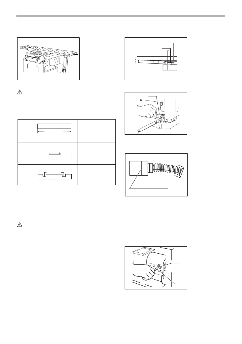
Adjusting height of sub-table
The height of sub-table is factory-adjusted. If further
adjustment is necessary, proceed as follows.
Place a postcard on the table and also place a ruler on
the postcard. Turn the adjusting screw with the hex
wrench until the end of the sub-table contacts the ruler.
Now the end of the sub-table is from 0.1 mm to 0.3 mm
(0.004” - 0.012”) above the table surface.
003728
1
Replacing carbon brushes
1. Hex wrench
001145
1. Limit mark
1
Remove and check the carbon brushes regularly.
Replace when they wear down to the limit mark. Keep
the carbon brushes clean and free to slip in the holders.
Both carbon brushes should be replaced at the same
time. Use only identical carbon brushes.
Use a screwdriver to remove the brush holder caps. Take
out the worn carbon brushes, insert the new ones and
secure the brush holder caps.
003729
1. Brush holder
cap
2. Screwdriver
1
2
8

Keeping planer blades sharp
Dull blades can cause rough finish, an overload of the
motor and dangerous kickback of the workpiece.
Replace dull blades immediately.
Lubrication
12
Oil the chain (after removing the side cover R), the four
columns and the screws for elevating the main frame.
This periodic lubrication should be performed with
machine oil.
CAUTION:
• Oiling and all maintenance should be done with the
tool turned off and unplugged.
003730
1. Column
2. Screw
3. Chain
3
Cleaning
Always brush off dirt, chips and foreign matter adhering
to the roller surfaces, motor vents and drums.
To maintain product SAFETY and RELIABILITY, repairs,
any other maintenance or adjustment should be performed by Makita Authorized or Factory Service Centers,
always using Makita replacement parts.
ACCESSORIES
CAUTION:
• These accessories or attachments are recom-
mended for use with your Makita tool specified in
this manual. The use of any other accessories or
attachments might present a risk of injury to persons. Only use accessory or attachment for its
stated purpose.
If you need any assistance for more details regarding
these accessories, ask your local Makita Service Center.
• Planer blade
• Planer stand
• Magnetic holder
• Socket wrench
• Hex wrench
• Hood set
MAKITA LIMITED ONE YEAR WARRANTY
EN0006-1
Warranty Policy
Every Makita tool is thoroughly inspected and tested
before leaving the factory. It is warranted to be free of
defects from workmanship and materials for the period of
ONE YEAR from the date of original purchase. Should
any trouble develop during this one year period, return
the COMPLETE tool, freight prepaid, to one of Makita’s
Factory or Authorized Service Centers. If inspection
shows the trouble is caused by defective workmanship or
material, Makita will repair (or at our option, replace)
without charge.
This Warranty does not apply where:
• repairs have been made or attempted by others:
• repairs are required because of normal wear and
tear:
• the tool has been abused, misused or improperly
maintained:
• alterations have been made to the tool.
IN NO EVENT SHALL MAKITA BE LIABLE FOR ANY
INDIRECT, INCIDENTAL OR CONSEQUENTIAL DAMAGES FROM THE SALE OR USE OF THE PRODUCT.
THIS DISCLAIMER APPLIES BOTH DURING AND
AFTER THE TERM OF THIS WARRANTY.
MAKITA DISCLAIMS LIABILITY FOR ANY IMPLIED
WARRANTIES, INCLUDING IMPLIED WARRANTIES
OF “MERCHANTABILITY” AND “FITNESS FOR A SPECIFIC PURPOSE,” AFTER THE ONE YEAR TERM OF
THIS WARRANTY.
This Warranty gives you specific legal rights, and you
may also have other rights which vary from state to state.
Some states do not allow the exclusion or limitation of
incidental or consequential damages, so the above limitation or exclusion may not apply to you. Some states do
not allow limitation on how long an implied warranty lasts,
so the above limitation may not apply to you.
9
 Loading...