

Makita 12 V 8413D, 18 V 8443D, 14.4 V 8433D Instruction Manual
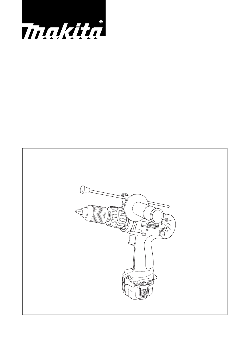
Cordless Percussion-Driver Drill
Instruction Manual
Akku-Schlagbohrschrauber
Betriebsanleitung
Bezprzewodowa udarowa wkrętarko-wiertarka
Instrukcja obsługi
Беспроводной бурильно-завинчивающий молоток
Инструкция по эксплуатации
12 V 8413D
14.4 V 8433D
18 V 8443D

1
3
2
12
4
4
9
5
7
8
6
10
11
34
12
10 12 14 16
13
14
15
13
56
16
17
18
19
78
2
20
21
24
22
23
16
25
910
11 12
26
27
13 14
29
30
15
28
3
Symbols
The following show the symbols used for the tool. Be sure that you understand their meaning before use.
Symbole
Die folgenden Symbole werden für die Maschine verwendet. Machen Sie sich vor der Benutzung unbedingt
mit ihrer Bedeutung vertraut.
Symbole
Poniższe symbole używane są do opisu urządzenia. Przed użyciem należy upewnić się, że rozumie się ich
znaczenie.
Символы
Следующие объяснения показывают символы, используемые для инструмента. Убедитесь перед
использованием, что Вы понимаете их значение.
❏ Indoor use only
❏ Nur für trockene Räume
Tylko do użytku w pomieszczeniach
❏
❏
Использование только внутри помещения
❏ Read instruction manual
❏ Bitte Betriebsanleitung lesen
Przeczytaj instrukcję obsługi
❏
❏
Прочитайте инструкцию по эксплуатации
❏ DOUBLE INSULATION
❏ DOPPELT SCHUTZISOLIERT
PODWÓJNA IZOLACJA
❏
❏
ДВОЙНАЯ ИЗОЛЯЦИЯ
❏ Ready to charge
Ladebereit
❏
❏
Gotowość do ładowania
❏
Готово для зарядки
❏ Charging
Akku wird geladen
❏
❏
Ładowanie
❏
Зарядка
❏ Charging complete
Laden beendet
❏
❏
Ładowanie zakończone
❏
Зарядка завершена
❏ Delay charge (too hot battery)
Ladungsverzögerung (Akku zu heiß)
❏
❏
Ładowanie opóźnione (zbyt ciepłe akumulatory)
❏
Задержка зарядки (слишком горячая батарея)
❏ Deffective battery
Akku defekt
❏
❏
Uszkodzony akumulator
❏
Дефектная батарея
4

❏ Do not short batteries
Schließen Sie die Kontakte nicht kurz. Brandgefahr!
❏
❏
Nie zwieraj akumulatorów
❏
Не закорачивайте батареи
❏ Always recycle batteries
❏ Verbrauchte Akkus stets dem Recycling zuführen
Zawsze kieruj akumulatory do odzysku
❏
❏
Всегда выбрасывайте батареи для рециркуляции
❏ Do not discard batteries into garbage can or the like
❏ Verbrauchte Akkus nicht in den Hausmüll werfen
Nigdy nie wyrzucaj akumulatorów do kosza na śmieci ani żadnego podobnego miejsca
❏
❏
Не выбрасывайте батареи в мусорный ящик или подобный контейнер
Note:
The recycling method may differ from country to country, or state (province) to state (province). Consult with
your nearest Makita Authorized Service Center or Distributor.
Achtung:
Die Art des Recycling kann von Land zu Land unterschiedlich sein. Bei Fragen wenden Sie sich an eine
autorisierte Werkstatt oder an den nächstgelegenen Makita-Kundendienst.
Uwaga:
Sposoby odzysku materiałów odpadowych mogą różnić się w poszczególnych krajach lub regionach (stanach). Poradź się najbliższego autoryzowanego punktu napraw lub dystrybutora firmy Makita.
Примечание:
Метод вторичной переработки может различаться в зависимости от страны или штата (провинции) .
Проконсультируйтесь с Вашим ближайшим уполномоченным центром по техобслуживанию Мakita или
дистрибьютером.
5

ENGLISH
Explanation of general view
1 Push button
2 Battery cartridge
3 Switch trigger
4 Reversing switch lever
5 A side
6 B side
7 Clockwise
8 Counterclockwise
9 Low speed
10 High speed
SPECIFICATIONS
Model 8413D 8433D 8443D
Capacities
Concrete ......................................................13 mm 14 mm 16 mm
Steel ............................................................13 mm 13 mm 13 mm
Wood ...........................................................30 mm 36 mm 38 mm
Wood screw .................................................6 mm x 75mm 6 mm x 75 mm 10 mm x 90 mm
Machine screw ............................................6 mm 6 mm 6 mm
No load speed (min
High .............................................................0 – 1,300 0 – 1,300 0 – 1,400
Low .............................................................. 0 – 400 0– 400 0 – 450
Blows per minute
High .............................................................0 – 19,500 0 – 19,500 0 – 21,000
Low .............................................................. 0 – 6,000 0 – 6,000 0 – 6,750
Overall length .................................................267 mm 267mm 267 mm
Net weight (with battery cartridge) .................2.3 kg 2.4 kg 2.6 kg
Rated voltage .................................................D.C.12 V D.C. 14.4 V D.C. 18 V
-1
)
11 Speed change lever
12 Action mode changing ring
13 Arrow
14 Adjusting ring
15 Graduations
16 Tighten
17 Sleeve
18 Bit
19 Bit holder
20 Grip base
21 Teeth
22 Side grip
23 Loosen
24 Depth rod
25 Thumb screw
26 Screw
27 Set plate
28 Limit mark
29 Brush holder cap
30 Screwdriver
• Due to our continuing program of research and devel-
opment, the specifications herein are subject to change
without notice.
• Note: Specifications may differ from country to country.
Intended use
The tool is intended for impact drilling in brick, concrete
and stone as well as for drilling without impact in wood,
metal, ceramic and plastic.
SAFETY INSTRUCTIONS
WARNING! When using battery operated tools basic
safety precautions, including the following, should
be followed to reduce the risk of fire, leaking batteries and personal injury: Read these instructions
before operating this product and save these instructions.
For safe operation:
1. Keep work area clean
– Cluttered areas and benches invite injuries.
2. Consider the work environment
– Do not expose the tool to rain. Keep work area well
lit. Do not use tools in the presence of flammable
liquids or gases.
3. Keep children away
– Do not let visitors touch the tool. Keep visitors
away from work area.
ENA002-1
6
4. Store batteries or idle tools
– When not in use, tools and batteries should be
stored separately in a dry, high or locked up place,
out of reach of children.
– Ensure that battery terminals cannot be shorted by
other metal parts such as screws, nails, etc.
5. Do not force the tool
– It will do the job better and safer at the rate for
which it was intended.
6. Use the right tool
– Do not force small tools or attachments to do the
job of a heavy duty tools. Do not use tools for purposes not intended.
7. Dress properly
– Do not wear loose clothing or jewellery, they can
be caught in moving parts. Non-skid footwear is
recommended when working outdoors. Wear protecting hair covering to contain long hair.
8. Use protective equipment
– Use safety glasses and if the cutting operation is
dusty, a face or dust mask.
9. Connect dust extraction equipment
– If devices are provided for the connection of dust
extraction and collection ensure these are connected and properly used.
10. Do not abuse the supply cord (if fitted)
– Never carry the tool by the cord or yank it to dis-
connect from the socket. Keep the cord away from
heat, oil and sharp edges.

11. Secure the work
– Use clamps or a vice to hold the work. It is safer
than using your hand and it frees both hands to
operate the tool.
12. Do not over-reach
– Keep proper footing and balance at all times.
13. Maintain tools with care
– Keep cutting tools sharp and clean for better and
safer performance. Follow instructions for lubrication and changing accessories. Inspect tool cords
periodically and if damaged have repaired by an
authorized service facility.
14. Disconnect tools
– Where the design permits, disconnect the tool
from its battery pack when not in use, before servicing and when changing accessories such as
blades, bits and cutters.
15. Remove adjusting keys and wrenches
– Form the habit of checking to see that keys and
adjusting wrenches are removed from the tool
before turning it on.
16. Avoid unintentional starting
– Do not carry the tool with a finger on the switch.
17. Stay alert
– Watch what you are doing. Use common sense.
Do not operate the tool when you are tired.
18. Check damaged parts
– Before further use of the tool, a guard or other part
that is damaged should be carefully checked to
determine that it will operate properly and perform
its intended function. Check for alignment of moving parts, free running of moving par ts, breakage
of parts, mounting and any other condition that
may affect its operation. A guard or other part that
is damaged should be properly repaired or
replaced by an authorized service facility unless
otherwise indicated in this instruction manual.
Have defective switches replaced by an authorized
service facility. Do not use the tool if the switch
does not turn it on and off.
19. Warning
– The use of any accessory or attachment, other
than recommended in this instruction manual or
the catalog, may present a risk of personal injury.
– Ensure that the battery pack is correct for the tool.
– Ensure that the outside surface of battery pack or
tool is clean and dry before plugging into charger.
– Ensure that batteries are charged using the cor-
rect charger recommended by the manufacturer.
Incorrect use may result in a risk of electric shock,
overheating or leakage of corrosive liquid from the
battery.
20. Have your tool repaired by a qualified person
– This tool is constructed in accordance with the rel-
evant safety requirements. Repairs should only be
carried out by qualified persons using original
spare parts, otherwise this may result in consider-
able danger to the user.
21. Disposal of battery
– Ensure battery is disposed of safety as instructed
by the manufacturer.
IMPORTANT SAFETY INSTRUCTIONS FOR
CHARGER & BATTERY CARTRIDGE
1. Before using battery cartridge, read all instructions and cautionary markings on (1) battery
charger, (2) battery, and (3) product using battery.
2. Do not disassemble battery cartridge.
3. If operating time has become excessively
shorter, stop operating immediately. It may
result in a risk of overheating, possible burns
and even an explosion.
4. If electrolyte gets into your eyes, rinse them out
with clear water and seek medical attention right
away. It may result in loss of your eyesight.
5. Always cover the batter y terminals with the battery cover when the battery cartridge is not
used.
6. Do not short the battery cartridge:
(1) Do not touch the terminals with any conduc-
tive material.
(2) Avoid storing battery cartridge in a container
with other metal objects such as nails, coins,
etc.
(3) Do not expose battery cartridge to water or
rain.
A battery short can cause a large current flow,
overheating, possible burns and even a breakdown.
7. Do not store the tool and battery cartridge in
locations where the temperature may reach or
exceed 50°C (122°F).
8. Do not incinerate the battery cartridge even if it
is severely damaged or is completely worn out.
The battery cartridge can explode in a fire.
9. Be careful not to drop or strike battery.
ENC004-1
SAVE THESE INSTRUCTIONS.
Tips for maintaining maximum battery life
1. Charge the battery cartridge before completely
discharged.
Always stop tool operation and charge the battery cartridge when you notice less tool power.
2. Never recharge a fully charged battery cartridge.
Overcharging shortens the battery service life.
3. Charge the battery cartridge with room temperature at 10°C – 40°C (50°F – 104°F). Let a hot battery cartridge cool down before charging it.
4. Charge the Nickel Metal Hydride battery cartridge when you do not use it for more than six
months.
ADDITIONAL SAFETY RULES
1. Be aware that this tool is always in an operating
condition, because it does not have to be
plugged into an electrical outlet.
2. Hold tool by insulated gripping surfaces when
performing an operation where the cutting tool
may contact hidden wiring. Contact with a “live”
wire will also make exposed metal parts of the
tool “live” and shock the operator.
3. Always be sure you have a firm footing.
4. Be sure no one is below when using the tool in
high locations.
ENB022-1
7

5. Hold the tool firmly.
6. Keep hands away from rotating parts.
7. Do not leave the tool running. Operate the tool
only when hand-held.
8. Do not touch the drill bit or the workpiece immediately after operation; they may be extremely
hot and could burn your skin.
SAVE THESE INSTRUCTIONS.
OPERATING INSTRUCTIONS
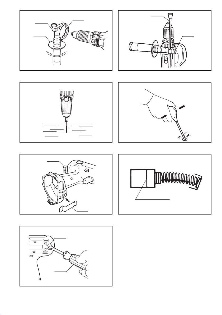
Installing or removing battery cartridge (Fig. 1)
• Always switch off the tool before insertion or removal of
the battery car tridge.
• To remove the battery cartridge, withdraw it from the
tool while pressing the buttons on both sides of the cartridge.
• To insert the battery cartridge, align the tongue on the
battery cartridge with the groove in the housing and slip
it into place. Always insert it all the way until it locks in
place with a little click. If not, it may accidentally fall out
of the tool, causing injury to you or someone around
you.
• Do not use force when inserting the battery cartridge. If
the cartridge does not slide in easily, it is not being
inserted correctly.
Switch action (Fig. 2)
CAUTION:
Before inserting the battery cartridge into the tool, always
check to see that the switch trigger actuates properly and
returns to the “OFF” position when released.
To start the tool, simply pull the trigger. tool speed is
increased by increasing pressure on the trigger. Release
the trigger to stop.
Reversing switch action (Fig. 3)
CAUTION:
• Always check the direction of rotation before operation.
• Use the reversing switch only after the tool comes to a
complete stop. Changing the direction of rotation
before the tool stops may damage the tool.
• When not operating the tool, always set the reversing
switch lever to the neutral position.
This tool has a reversing switch to change the direction of
rotation. Depress the reversing switch lever from the A
side for clockwise rotation or from the B side for counterclockwise rotation. When the switch lever is in the neutral
position, the switch trigger cannot be pulled.
Speed change (Fig. 4)
To change the speed, first switch off the tool and then
slide the speed change lever to the “ II ” side for high
speed or “ I ” side for low speed. Be sure that the speed
change lever is set to the correct position before operation. Use the right speed for your job.
CAUTION:
• Always set the speed change lever fully to the correct
position. If you operate the tool with the speed change
lever positioned half-way between the “ I ” side and “ II ”
side, the tool may be damaged.
• Do not use the speed change lever while the tool is running. The tool may be damaged.
Selecting the action mode (Fig. 5)
This tool employs an action mode changing ring. Select
one of the three modes suitable for your work needs by
using this ring. For rotation only, turn the ring so that the
arrow on the tool body points toward the M mark on the
ring. For rotation with hammering, turn the ring so that
the arrow points toward the X on the ring. For rotation
with clutch, turn the ring so that the arrow points toward
the U mark on the ring.
CAUTION:
Always set the ring correctly to your desired mode mark.
If you operate the tool with the ring positioned half-way
between the mode marks, the tool may be damaged.
Adjusting the fastening torque (Fig. 6)
The fastening torque can be adjusted in 16 steps by turning the adjusting ring so that its graduations are aligned
with the arrow on the tool body. The fastening torque is
minimum when the number 1 is aligned with the arrow,
and maximum when thenumber 16 is aligned with the
arrow.
Before actual operation, drive a trial screw into your
material or a piece of duplicate material to determine
which torque level is required for a particular application.
Installing or removing driver bit or drill bit
(Fig.7 & 8)
Important:
Always be sure that the tool is switched off and the battery cartridge is removed before installing or removing
the bit.
Turn the sleeve counterclockwise to open the chuck jaws.
Place the bit in the chuck as far as it will go. Turn the
sleeve clockwise to tighten the chuck. To remove the bit,
turn the sleeve counterclockwise.
When not using the driver bit, keep it in the bit holders.
Bits 45 mm long can be kept there.
Side grip (auxiliary handle) (Fig. 9)
Always use the side grip to ensure operating safety.
Install the side grip so that the teeth on the grip fit in
between the protrusions on the tool barrel. Then tighten
the grip by turning clockwise at the desired position. It
may be swung 360° so as to be secured at any position.
Adjustable depth rod (Fig. 10)
The adjustable depth rod is used to drill holes of uniform
depth. Loosen the thumb screw, set to desired position,
then tighten the thumb screw.
8

Screwdriving operation (Fig. 11)
First, turn the action mode changing ring so that the
arrow on the tool body points to the U marking. Adjust
the adjusting ring to the proper torque level for your work.
Then proceed as follows.
Place the point of the driver bit in the screw head and
apply pressure to the tool. Start the tool slowly and then
increase the speed gradually. Release the trigger as
soon as the clutch cuts in.
NOTE:
• Make sure that the driver bit is inser ted straight in the
screw head, or the screw and/or bit may be damaged.
• When driving wood screws, predrill pilot holes to make
driving easier and to prevent splitting of the workpiece.
See the chart below.
Nominal diameter
of wood screw (mm)
3.1 2.0–2.2
3.5 2.2–2.5
3.8 2.5–2.8
4.5 2.9–3.2
4.8 3.1–3.4
5.1 3.3–3.6
5.5 3.6–3.9
5.8 4.0–4.2
6.1 4.2–4.4
• If the tool is operated continuously until the battery cartridge has discharged, allow the tool to rest for 15 minutes before proceeding with a fresh battery.
Drilling operation
First, turn the action mode changing ring so that the
arrow on the tool body points to the M marking. The
adjusting ring can be aligned in any torque levels for this
operation. Then proceed as follows.
• Drilling in wood
When drilling in wood, best results are obtained with
wood drills equipped with a guide screw. The guide
screw makes drilling easier by pulling the bit into the
workpiece.
• Drilling in metal
To prevent the bit from slipping when starting a hole,
make an indentation with a centerpunch and hammer
at the point to be drilled. Place the point of the bit in the
indentation and start drilling. Use a cutting lubricant
when drilling metals. The exceptions are iron and brass
which should be drilled dry.
Recommended size
of pilot hole (mm)
CAUTION:
• Pressing excessively on the tool will not speed up the
drilling. In fact, this excessive pressure will only serve
to damage the tip of your bit, decrease the tool performance and shor ten the service life of the tool.
• There is a tremendous force exerted on the tool/bit at
the time of hole breakthrough. Hold the tool firmly and
exert care when the bit begins to break through the
workpiece.
• A stuck bit can be removed simply by setting the
reversing switch to reverse rotation in order to back out.
However, the tool may back out abruptly if you do not
hold it firmly.
• Always secure small workpieces in a vise or similar
hold-down device.
• If the tool is operated continuously until the battery cartridge has discharged, allow the tool to rest for 15 minutes before proceeding with a fresh battery.
Hammer drilling operation
First, turn the action mode changing ring so that the
arrow on the tool body points to the X marking. The
adjusting ring can be aligned in any torque levels for this
operation. Position the bit at the desired location for the
hole, then pull the trigger. Do not force the tool. Light
pressure gives best results. Keep the tool in position and
prevent it from slipping away from the hole. Do not apply
more pressure when the hole becomes clogged with
chips or particles. Instead, run the tool at an idle, then
remove the bit partially from the hole. By repeating this
several times, the hole will be cleaned out and normal
drilling may be resumed.
CAUTION:
There is a tremendous and sudden twisting force exerted
on the tool/bit at the time of hole breakthrough, when the
hole becomes clogged with chips and par ticles, or when
striking reinforcing rods embedded in the concrete.
Always use the side grip (auxiliary handle) and firmly
hold the tool by both side grip and switch handle during
operations. Failure to do so may result in the loss of control of the tool and potentially severe injury.
Blow-out bulb (Fig. 12)
Use the blow-out bulb to clean out the hole.
Installing set plate (Fig. 13)
For 8413D
Always install the set plate when using battery cartridges
1200, 1202 or 1202A. Install the set plate on the tool with
the screw provided.
9
 Loading...