

Make Noise DPO User Manual
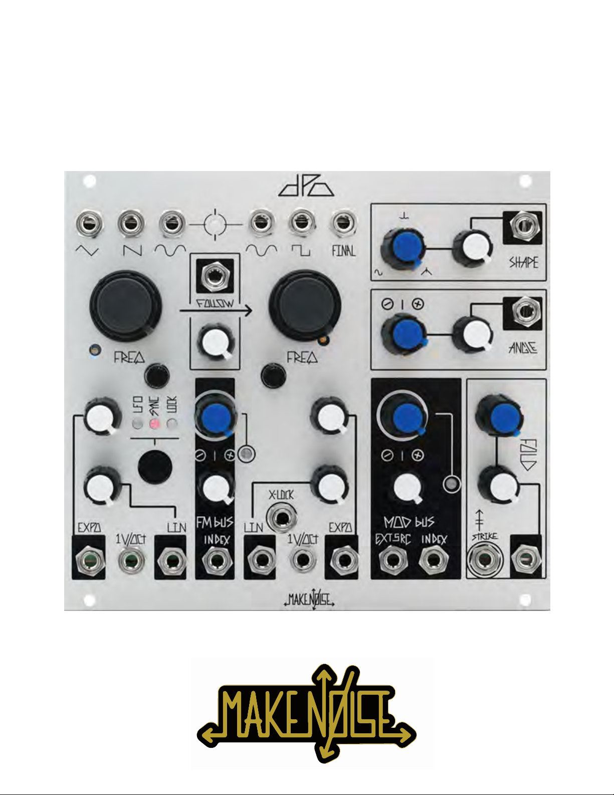
DPO

Limited WARRANTY:
Make Noise warrants this product to be free of defects in materials or construction for a period of one year
from the date of purchase (proof of purchase/invoice required).
Malfunction resulting from wrong power supply voltages, backwards power cable connection, abuse of the
product or any other causes determined by Make Noise to be the fault of the user are not covered by this
warranty, and normal service rates will apply.
During the warranty period, any defective products will be repaired or replaced, at the option of Make Noise,
on a return-to-Make Noise basis, with the customer paying the transit cost to Make Noise.
Please contact Make Noise for Return To Manufacturer Authorization.
Make Noise implies and accepts no responsibility for harm to person or apparatus caused through
operation of this product.
Please contact technical@makenoisemusic.com with any questions, needs & comments... otherwise go
MAKE NOISE.
http://www.makenoisemusic.com
THANK YOU
Beta Analyst: Surachai
Test Subjects: Rob Lowe, Joseph Raglani
Spiritual Advisor: Richard Devine
Special Thanx to Don Buchla for his original and inspirational 259 and Music Easel.
Installation:
The Make Noise DPO is an electronic signal generator requiring 70mA of +/-12V of regulated power and
properly formatted distribution receptacle to operate. It is designed to be used within the euro format
modular synthesizer system.
Go to http://www.doepfer.de/a100_man/a100t_e.htm for the details of this format.
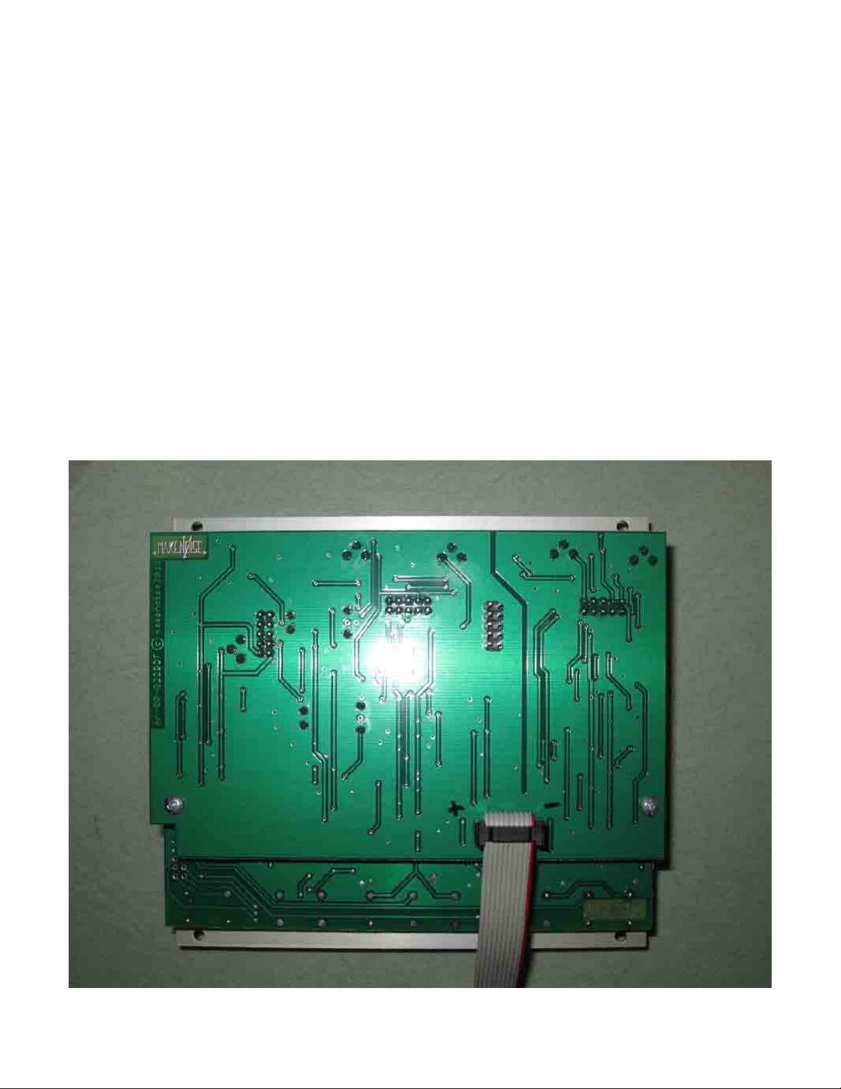
To install, find 28HP of space in your euro-rack synthesizer system, confirm proper installation of included
power cable on backside of module (see picture below), plug the 16 pin end power cable into the euro-rack
style power distribution board, minding the polarity so that the RED stripe on the cable is oriented to the
NEGATIVE 12 volt supply line. This is USUALLY at the bottom.
Please refer to your case manufacturers’ specifications for location of the negative supply.
Proper installation of included power cable on module.
Please note the RED BAND.

Overview:
The DPO is a voltage controlled oscillator designed for generating complex waveforms and
implementing FM synthesis within the analog domain. Expanding on the classic arrangement
of Primary and Modulator Oscillators, the DPO has both of the VCOs operable as complex
signal sources. It is in essence a Dual Primary Oscillator.
The DPO is also designed for fast live sound creation. The module groups functionality
intuitively to make complex patching move more quickly, while still interacting in an exciting
way with all other modules.
Dynamic FM, Circular FM, Hard Sync and Additive Harmonic synthesis processes are all
achieved with internal routing on the DPO. The idea being that the artist will utilize patch
cables to expand upon these standard concepts or interrupt them completely by simply
patching into the associated modulation destinations.
The DPO has two modulation buses, each with multiple destinations, the depth of which is
adjustable per destination. The original 259 style modulation routing is split within the DPO
into dedicated FM and Mod buses and switching jacks are utilized to create internal routings
that may be undone by patching an external signal to the CV inputs. The attenuator
associated with the destination CV input sets the final depth while the MOD and FM INDEX
controls will act as the dynamic master depth controls.
Throughout the DPO opto-isolators, commonly called Vactrols, are utilized as gain cells, and
the result is that the module will have a slow and organic response to control signals. This
manifests itself in the smooth crossfading and phase reversal of the SHAPE parameter, for
example.
The DPO is a 100% analog, vintage voiced musical instrument and is not suitable for
laboratory use.
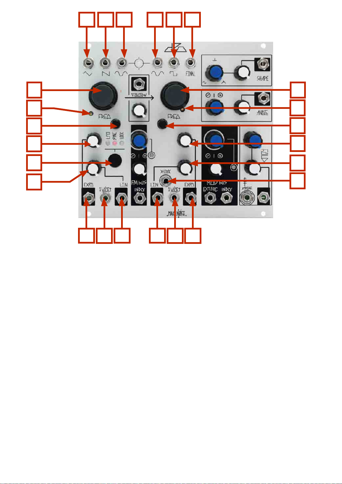
1A 2A 3A 1B 2B 3B
4A
5A
6A
7A
12A
8A
9A
10A
VCO A
1A Triangle Waveform OUT: 10Vpp
2A Sawtooth Waveform OUT: 9Vpp
3A Sine Waveform OUT: 10Vpp
4A Coarse Tune panel control: 9.5 octave range 12hz-6khz
5A 1V/ Octave Scale Trimmer (see calibration procedure)
6A Fine Tune panel control: 1.75 octave range
7A Expo Attenuator: uni-polar attenuator for Exponential frequency control input
8A Linear FM Attenuator: uni-polar attenuator for Linear FM input
9A Expo INput: Exponential frequency control input. normalled to FM Bus. bi-polar, 10V range
10A 1V/ Octave control INput: bi-polar pitch control, optimal range +/-5V
11A Linear FM INput: AC coupled, normalled to FM Bus, 10V range
12A VCO core behavior (Indicated by LED): No LED: Standard, BLUE: Phase LOCK to VCO B; PINK:
Hard SYNC to VCO B; AMBER: Low Frequency Oscillator.
VCO B
1B Sine Waveform OUT: 10Vpp
2B Square Waveform OUT: 9Vpp Asymmetrical
3B FINAL Waveform: max 10Vpp Waveform as processed by Shape, Angle & Fold circuits
4B Coarse Tune panel control: 9.5 octave range 12hz-6khz
5B 1V/ Octave Scale Trimmer (see calibration procedure)
6B Fine Tune panel control: 1.75 octave range
7B Exponential Attenuator: uni-polar attenuator for Exponential frequency control input
8B Linear FM Attenuator: uni-polar attenuator for Linear FM input
9B Linear FM INput: AC coupled, normalled to FM Bus, 10V range
10A 1V/ Octave control INput: bi-polar pitch control, optimal range +/-5V
11B Expo INput: Exponential frequency control input. normalled to FM Bus. bi-polar, 10V range
12B eXternal-LOCK: allows VCO B to phase locked to hard edged signal (square, pulse or Sawtooth)
from other VCOs.
11A
9B
10B
11B
4B
5B
6B
7B
8B
12B
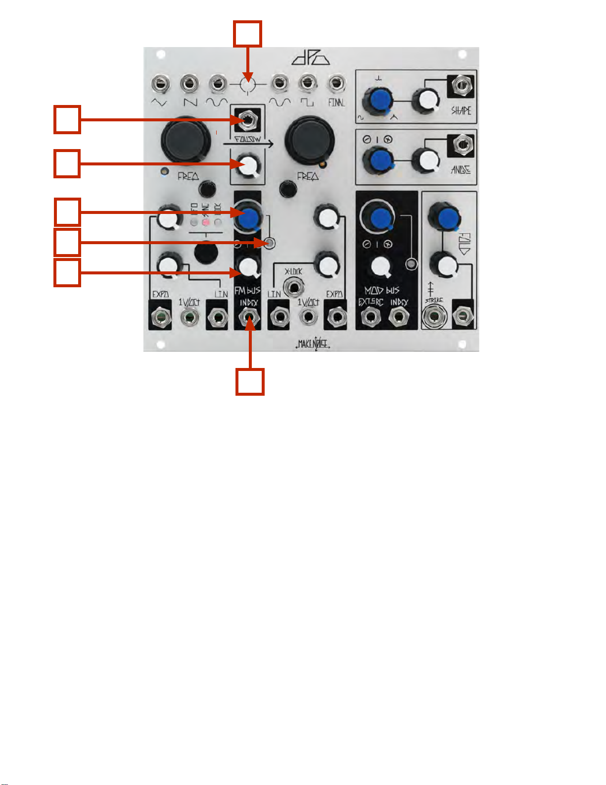
1
2
3
4
5
6
7
VCO Interaction
1. Beat Frequency LED: visual indication of Phase difference between VCOs A & B.
2. FOLLOW CV INput: unipolar control input. Range 0V to 5V.
3. FOLLOW Attenuator: determines how well VCO A will FOLLOW VCO B. With nothing patched to
FOLLOW CV IN works as standard panel control. With Signal Patched to FOLLOW CV IN, works
as an attenuator for that signal.
4. FM BUS INDEX: unipolar panel control that sets the index (depth) of the FM.
5. FM BUS INDEX LED: indicates the currently programmed FM Index Value.
6. FM BUS INDEX CV Attenuator: bipolar attenuator for FM BUS INDEX CV IN
7. FM BUS INDEX CV IN: bipolar control signal input. Range +/- 4V
 Loading...