

Page 1
Erbe-Verb
Page 2

Limited WARRANTY:
Make Noise warrants this product to be free of defects in materials or construction for a period of one year
from the date of purchase (proof of purchase/invoice required).
Malfunction resulting from wrong power supply voltages, backwards power cable connection, abuse of the
product or any other causes determined by Make Noise to be the fault of the user are not covered by this
warranty, and normal service rates will apply.
During the warranty period, any defective products will be repaired or replaced, at the option of Make Noise,
on a return-to-Make Noise basis with the customer paying the transit cost to Make Noise. Please contact
Make Noise for Return To Manufacturer Authorization.
Make Noise implies and accepts no responsibility for harm to person or apparatus caused through operation
of this product.
Please contact [email protected] with any questions, needs & comments, otherwise...
go MAKE NOISE!
http://www.makenoisemusic.com
Page 3
Installation:
The Make Noise Erbe-Verb is an electronic signal router requiring 149mA of +12V and 13mA
of regulated power and a properly formatted distribution receptacle to operate. It is designed
to be used within the euro format modular synthesizer system.
Go to http://www.doepfer.de/a100_man/a100t_e.htm for the details of this format.
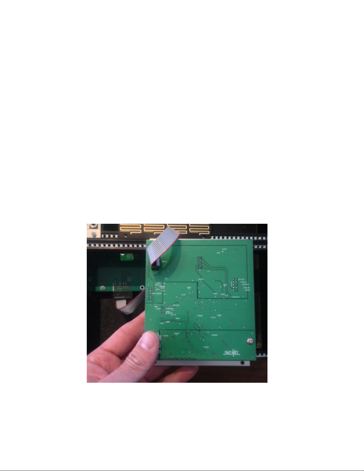
To install, find 20 HP of space in your euro-rack synthesizer system, confirm proper installation of included power cable on backside of module (see picture below), plug the 16 pin end
power cable into the euro-rack style power distribution board, minding the polarity so that the
RED stripe on the cable is oriented to the NEGATIVE 12 volt supply line. On the Make Noise
power bus board, the negative 12 volt supply is indicated by the white stripe.
Please refer to your case manufacturers’ specifications for location of the negative supply.
Page 4
1b
2a
2b
5a
5b
1a
4a
4b
3a
3b
4c
5c
Erbe-Verb Panel Controls
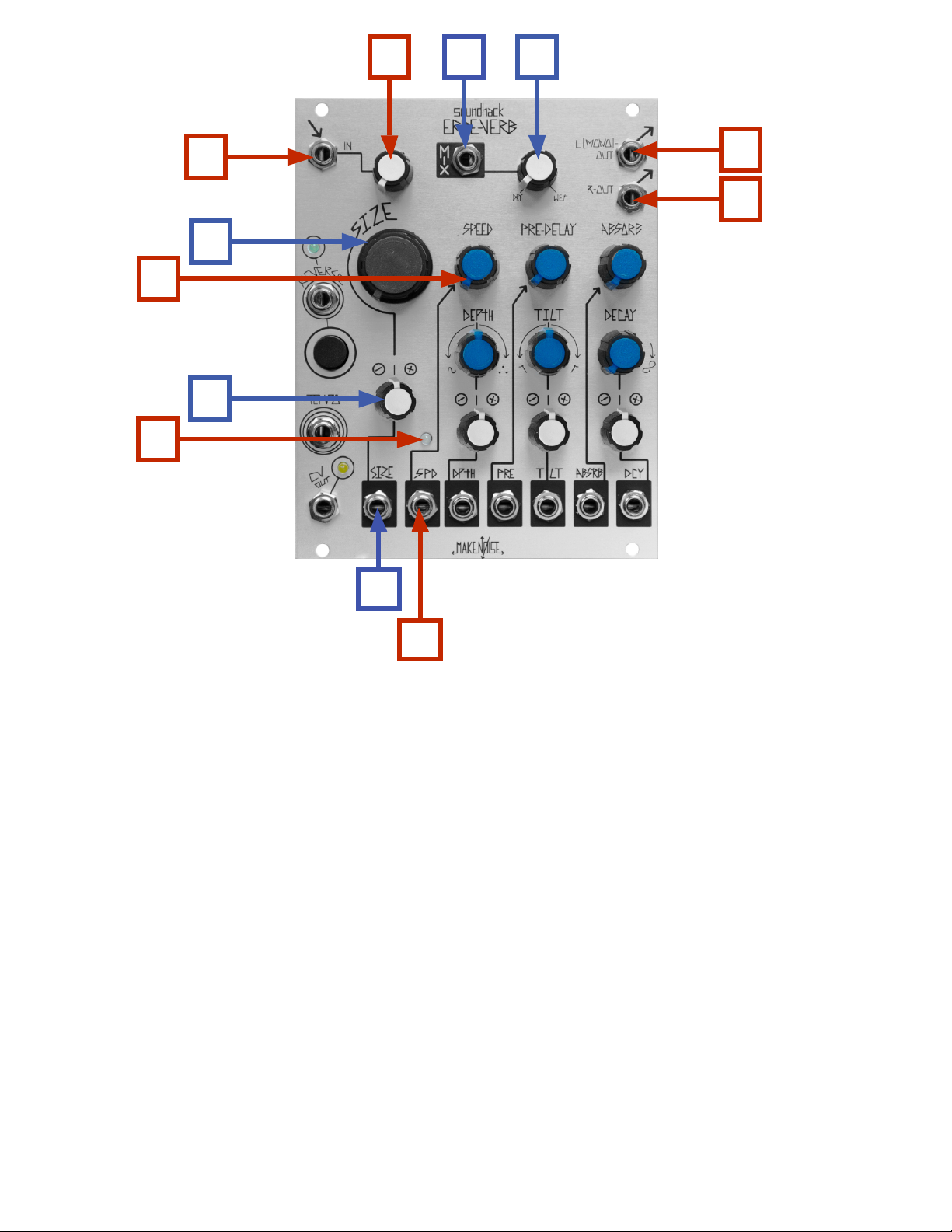
1a. Signal IN: AC coupled, expects standard signal level of 10Vpp signal.
1b. Level Control for Signal IN: unity at 3 o' Clock
2a. MIX CV IN: unipolar control input. Range 0V to +5V.
2b. MIX Panel Control: blends between DRY (un-processed) signal & WET (processed) Signal. Operates as
Combo Knob, with nothing patched to MIX CV IN, works as standard panel control. With
Signal Patched to MIX CV IN, works as attenuator for that signal.
3a. Left (MONO) Output: 10Vpp (depending upon Level setting and source material), AC coupled. Left portion
of Stereo reverb image, also serves as MONO reverb image.
3b. Right Output: 10Vpp (depending upon Level setting and source material), AC coupled. Right portion of
Stereo reverb image.
4a. SIZE Panel Control: unipolar panel control that sets the Size of the space. Ranges from "coffin" to
"heavens." 35 cu. ft. - 9.3 million cu. ft.
4b. SIZE CV Attenuator: bi-polar attenuator for Size CV IN.
4c. SIZE CV IN: control signal input for Size. Range +/- 5V.
5a. SPEED Panel Control: uni-polar control for Speed of internal modulation.
Using internal clock: 1/2cps - 256 cps, using ext. clock 1/48cps - 9000 cps
5b. SPEED LED: visual indication of Internal Modulation rate.
5c. SPEED CV IN: control signal input for Speed. Range +/- 5V.
Page 5
7a
9a
6a
6b
6c
7b
8c
9b
8a
8b
Erbe-Verb Panel Controls (cont’d)
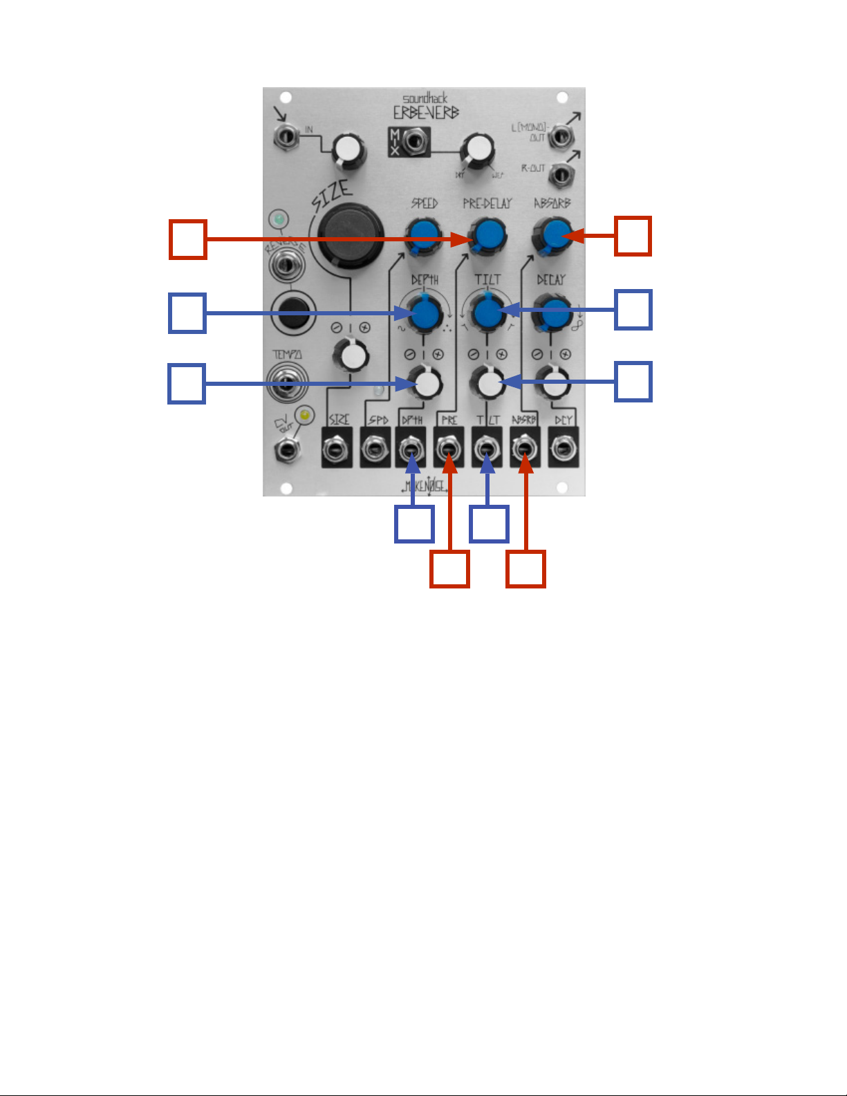
6a. DEPTH Panel Control: bi-polar control for Depth and Type of Internal Modulation. Minimum modulation
at NOON. Cyclic modulation CCW from NOON. Ergodic modulation CW from NOON.
Shimmer at Full CW.
6b. DEPTH CV Attenuator: bi-polar attenuator for Depth CV IN.
6c. DEPTH CV IN: control signal input for Depth. Range +/- 5V.
7a. PRE-DELAY Panel Control: control for amount of Pre-Delay or Reverse time. Using internal clock,
operates as uni-polar with a range of 7ms - 500ms. Using ext. clock operates as bi-polar w/
divisors & multipliers of 1/12,1/8, 1/6, 1/4, 1/3, 1/2, 2/3, 1/1, 3/2, 2/1, 3/1, 4/1, 6/1, 8/1, 12/1
where 1/1 is at NOON.
7b. PRE-DELAY CV IN: control signal input for Pre-Delay. Range +/- 5V.
8a. TILT Panel Control: bi-polar control for Tilt. Low Gain +12 dB to -12 dB, High Gain -24dB to + 24dB,
unity at NOON.
8b. TILT CV Attenuator: bi-polar attenuator for Tilt CV IN.
8c. TILT CV IN: control signal input for Tilt. Range +/- 5V.
9a. ABSORB Panel Control: uni-polar control for Absorption. Full CCW = 0 diffusion, 0 damping;
10 o'clock = full diffusion, 0 damping; Full CW = full diffusion, full damping.
9b. ABSORB CV IN: control signal input for Absorption. Range +/- 5V.
Page 6
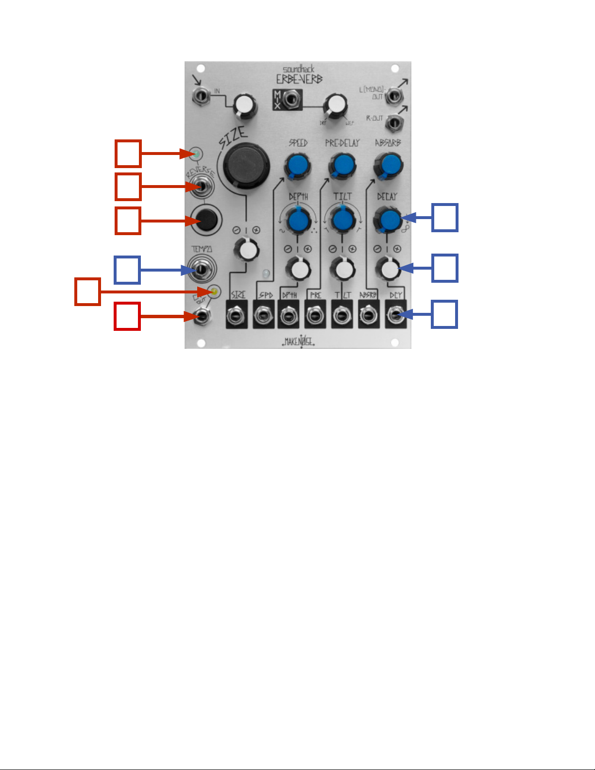
11a
11b
11c
12
10a
10b
13a
13b
10c
Erbe-Verb Panel Controls (cont’d)
10a. DECAY Panel Control: uni-polar control for Decay. 0 - 120% reflection gain. Infinity at Full CW.
10b. DECAY CV Attenuator: bi-polar attenuator for Decay CV IN.
10c. DECAY CV IN: control signal input for Decay. Range +/- 5V.
11a. REVERSE LED: visual indication of Reverse. Lights when Reverse is engaged, flickers to
indicate Reverse buffer rate.
11b. REVERSE Gate IN: will Reverse on Gate HIGH. Momentary action. 1.5V trigger signal to operate.
11c. REVERSE Button: toggles Reverse on/ off. In Reverse Pre-Delay (7a, 7b) determines Reverse buffer
size. Using internal clock: 42ms - 500ms; using external clock: 0.1ms - 5.46s synchronized.
12. TEMPO IN: allows synchronization of Echoes to multiple or division of an external Clock.
While following external Tempo the Speed (5a, 5b, 5c) and Pre-Delay (7a, 7b) will be multiple
or division of the incoming clock. Requires Clock/ Gate signal amplitude of at least 1.5V and
width of at least 6ms.
13a. CV OUT LED: visual indication of the CV OUT signal.
13b. CV OUT: control signal representing the average energy of the algorithm. Range 0V - 10V
Page 7

Getting Started:
Patch the signal to be processed into the SIGNAL IN (1a). The associated Level Control (1b) accommodates modular
synthesizer signals of 10Vpp with unity gain at around 3 o' Clock. Beyond 3 o' Clock on the Level Control, there will
be some gain and possibly clipping followed by digital overloading. Take your output from the LEFT OUT (3a) and
patch to your nal mixer/ monitoring system. If you have Stereo monitoring, patch both LEFT OUT (3a) and RIGHT
OUT (3b) to your Stereo monitor inputs. MIX (2b) is a blend between the dry analog signal and the wet digitally
processed signal. Set the MIX Panel Control (2b) to about 11 o' clock for the typical reverb eect.
Size:
The large grey knob, SIZE (4a), is the most dening parameter of the Erbe-Verb sound. It is an ultra-wide range
control over the size of the virtual space. It goes from unrealistically small (full CCW), to unrealistically large (Full CW),
with the full spectrum of realism between. In reverbs the Size parameter is often buried in the reverb algorithm or
preset. If there is a Size parameter to adjust it is usually limited in range to t the algorithm. So for example, a Room
algorithm might allow size to be varied from .3 - .10 secs. On the Erbe-Verb the entire range of possible size is
available at all times. This means it is possible to travel from one space to another or to modulate between several
spaces. Typical settings for the Size parameter are as follows:
Con: Full CCW
Room: 12 o' Clock
Plate: 1 to 2 o' Clock
Hall: 3 o' Clock
Ambient: 4 o' Clock
Heaven: Full CW
Directly beneath this panel control are the SIZE CV Attenuator (4b) and SIZE CV IN (4c). Use the SIZE CV IN (4c) to
modulate the Size parameter. This allows for morphing between spaces or creating spaces that are large at one end
and small at the other. Modulation of this parameter will be very dramatic, so use the SIZE CV Attenuator (4b) to
create more subtle modulations.
Predelay
Toward the center of the Erbe-Verb is PRE-DELAY (7a). This controls the amount of time before reections from walls
of the virtual space start arriving to the listener. In many reverbs and in the physical world the range of pre-delay is
tied directly to the size parameter. Small spaces have very little pre-delay. As the space increases in size, so does the
possible amount of pre-delay. The Erbe-Verb has a wide ranging Pre-Delay, 7ms to 500ms, that is completely
independent of the Size control. Therefore you could have a really small space (set SIZE to 10 o' clock) that was far
away (set PRE-DELAY to Full CW). On the contrary you could have a massive space (set SIZE to 3 o' clock) where the
reections arrive almost immediately (set PRE-DELAY to Full CCW). Of course these settings are not very realistic, but
it could be inspiring and fun to put the listener in a space that does not exist in our physical world. Typically larger
space Sizes will have more Pre-Delay and smaller space Sizes will have less. Here are some typical settings for
Pre-Delay with reference to the Size parameter:
Con: Full CCW
Room: 9 o' Clock
Plate: Full CCW
Hall: 11 o' Clock
Ambient: 11 o' Clock
Heaven: Full CW
Page 8

Predelay (cont’d)
In addition to being wide ranging and completely independent of the Size parameter, the Erbe-Verb Pre-Delay is
also able to be synchronized to the rest of the modular system. Using the TEMPO IN (12a), it may be synced to a
division (CW from NOON) or multiple (CCW from NOON) of the clock patched to TEMPO IN (12a). This is highly
un-realistic. Nowhere in nature is the trajectory of sound synchronized to a machine. The Reverse function reverses
time by playing the Pre-Delay buer backwards. This creates Reverse Reverberations. This may occur in nature, but
we are not yet certain. Reverse time is set by the PRE-DELAY controls (7a, 7b). Reverse may be toggled On/ O by the
associated REVERSE Button (11c), and momentarily engaged using the REVERSE Gate IN (11b). Like Pre-Delay, using
the TEMPO IN (12a) Reverse may be synced to a division or multiple of the input clock.
The Pre-Delay parameter has a unity gain control signal input PRE-DELAY CV IN (7b) allowing for voltage control. This
also aids in morphing between spaces or creating unusual circumstances within the space such as constantly
moving the listener from the mouth of a cavern to it's depths. Fast modulation or sweeping of this parameter will
result in pitch shifting as well. Audio rate modulation of this parameter could be very pleasing, as it creates
gorgeously metallic tones. Because there is no attenuator associated with this parameter, it could be helpful to patch
the desired control source to a channel of MATHS for attenuation prior to the Pre-Delay CV IN destination.
Decay:
After Size, the most dramatic parameter on the Erbe-Verb is DECAY (10a) which changes the length of the reverb
"tail," from very short all the way up to innity. In some ways this control is similar to the FEEDBACK controls on the
ECHOPHON and other Echo or Delay processors. Decay uses internal feedback to put energy back into the reverb
algorithm, resulting in sustaining the reverb. This sustaining increases the time it takes for the reverberations to
settle, or decay to zero amplitude. Decay is by nature a function of Size. Smaller spaces tend to have shorter Decay
times while Larger spaces tend to have longer Decay times. Some typical Decay settings for example:
Con: 9 o' Clock
Room: 12 o' Clock
Plate: 1 to 2o'Clock
Hall: 11 to 2 o' Clock
Ambient: 11 to 2 o' Clock
Heaven: Full CW
Directly beneath the DECAY Panel control are the DECAY CV Attenuator (10b) and DECAY CV IN (10c). Use the DECAY
CV IN (10c) to modulate the Decay parameter. This allows for morphing between spaces or creating spaces where
the energy is uctuating. Use the DECAY CV IN (10c) to create more subtle modulations. Because the Decay
parameter is feedback based, the response will be slower then that of the Size or Pre-Delay parameters. Therefore
greater impact will be achieve with slower control signals such as envelopes from MATHS or Function w/ long Rise or
Fall settings, LFOs from MATHS or Function, slower random voltages from the Wogglebug (Smooth or Stepped) and
sequences from Pressure Points that are clocked at a division of the master clock.
Page 9

Internal Modulation (Speed and Depth)
Decay is also greatly inuenced by the SPEED (5a, 5c) and DEPTH (6a, 6b, 6c) settings since the Internal Modulation
has the potential to take energy away from the reverb process, which results in decreasing settle times. For example
setting Depth and Speed to about 4 o' Clock will smooth out resonances in the space and cause the reverb to settle
more quickly.
Using the Internal Modulation, SPEED (5a) and DEPTH (6a), is not like using external modulation such as LFOs and
Random Voltages from the modular system. The Internal Modulation is embedded in the reverb algorithm, and may
have a very dramatic eect on the sound of the reverb, adding and removing energy, diusing and detuning pitched
sounds. A small amount of Internal Modulation is useful for smoothing resonances and reigning in the Decay
parameter. A larger amount of Internal Modulation can create chorused, doppler, ambient and shimmered sounds.
When used with Innite Decay (DECAY set Full CW) Internal Modulation can create innitely evolving washes, ghost
choirs, bowed gongs and shifting feedback.
The modulation DEPTH (6a) controls both the amount and type of modulation: increasingly Cyclic to the left, and
increasingly Ergodic to the right. At the NOON the Internal Modulation is minimized. Cyclic modulation is a
multiphase cascaded chorus eect, which ranges from very subtle chorusing to extreme doppler swirls. Ergodic
modulation causes random room dimension shifting, which can become very granular at high depth. At the top of
the range on the Ergodic side there will be "Shimmering."
The user also has control over the SPEED (5a) of this modulation. At high Speed settings, Internal Modulation has the
eect of smoothing out the aural response of the whole algorithm and is useful for creating long but natural
sounding sustains. The slower range of the Erbe-Verb Speed parameter is atypical of reverb behavior in nature and is
not often found in reverb algorithms. At low Speed settings Internal Modulation is more discernible as a rhythmic
eect such as Chorusing, Evolving and Swirling. The speed may be synced to a multiple or division of an input clock
using the TEMPO IN (12a).
Note: with depth at noon (zero modulation), speed will have no discernable eect.
Absorb:
The ABSORB parameters (9a, 9b) will also have a great deal of inuence on the Decay. Absorb will aect both the
tone and the time of the Decay. Increasing the Absorb parameter value will decrease the Decay times and also have
the eect of making the reverb tail sound darker.
The ABSORB (9a, 9b) parameter is combination of controlling both Diusion and Damping within the space. Here's
how it works:
Full CCW = 0 diusion, 0 damping
10 o'clock = full diusion, 0 damping
Full CW = full diusion, full damping
Page 10

Absorb (cont’d)
Diusion:
Diusion controls the degree to which initial reverb density increases over time. High amounts of Diusion result in
fast initial buildup of echo density; low amounts cause slow initial buildup. Diusion is also aected by Size —
smaller spaces will sound denser because the sound travels shorter distances before reecting and returning to the
listener. Diusion is also related to the shape and construction of a room. To enhance percussive sounds, use high
amounts of Diusion. This will make the space sound more alive. For creating clear, easily discernible vocal sounds
use low amount of diusion.
Damping:
The Damping parameter controls the amount of high-frequency, damping, architectural details to the space such as
thick rugs, velvet wall coverings and scattered people. In doing so it removes high frequency energy from the reverb
over time. Increasing the amount of Damping will result decreased settle times and a darker overall reverb sound.
This will make the space sound more dead.
Because the Absorb parameter is feedback based, the response will be slower then that of the Size or Pre-Delay
parameters. Therefore greater impact will be achieve with slower control signals such as envelopes from MATHS or
Function w/ long Rise or Fall settings, LFOs from MATHS or Function, slower random voltages from the Wogglebug
(Smooth or Stepped) and sequences from Pressure Points that are clocked at a division of the master clock.
Note: Absorb is highly inuenced by the Decay parameter. The greater the Decay setting, the more dramatic
the Absorb response.
Tilt:
Below PRE-DELAY is TILT (8a). This parameter shapes the nal tone of the reverb. It is the last operation in the
algorithm so it has no eect on the energy, feedback or nature of the reverberations. It is completely independent of
the reverberation process. At NOON the frequency response is not altered by the Tilt parameter. As you turn the TILT
panel control CCW the High-End is slightly cut and the Low end is dramatically boosted, resulting in thick,
thunderous sounds that will ll out empty spaces. As you turn it CW the Low-End is cut and the High-End is
dramatically boosted, resulting in thinner, bright sound that allows plenty of room in the space for other
instruments. The Tilt parameter is highly useful for tailoring the reverb sound to t well with the rest of your patch. If
your patch is spacious and there is plenty of room then Tilting toward the Low end will ll out the sound nicely. if
your patch is already lled out, then Tilting for High Boost will add sparkle and interesting detail to the sound
without becoming obtrusive. TILT CV Attenuator and TILT CV IN (8b, 8c) provide voltage control over the Tilt
parameter. While Tilt might seem to be more of a utility function, creative modulation of this parameter may have
highly interesting results. The Tilt parameter responds well to slow modulation rates and especially with longer
Decay times it will have a dramatic eect not unlike phase shifting.
CV Output:
In addition to the CV inputs on the Erbe-Verb there is also one CV output. The CV OUT (13b) is the result of an
envelope follower, and it goes higher as the reverb signal gets louder. This can be very useful for patching back into
the system or into the reverb itself. For example, patching it to the ABSORB CV IN (9b) or DECAY CV IN (10c) w/
inversion by DECAY CV Attenuator (10b) creates an automated "reigning in" of the reverb when feedback starts to
get out of hand. Much more dramatic modulations may be achieved by patching the CV OUT to SIZE (4c). Patching
the CV OUT to destinations outside the Erbe-Verb completes the conversation between the Erbe-Verb and the rest of
the system.
Page 11

Emulating Typical Reverb Rooms :
Note: For all algorithms, Size, PreDelay and Decay settings are given. Small variances in these three controls will alter
the room. Set Speed and Depth to 12:00, and Absorb full CCW, unless otherwise noted, then set Tilt to taste to t the
sound into the mix. Keep in mind that these are starting points, and many spaces in between are possible by taking
any control out of its comfort zone.
Con
Size: full CCW
PreDelay: full CCW
Decay: 9:00
Absorb: (low-cost oak) 9:00; (luxury) 2:00
Room
Size: 12:00
PreDelay: 12:00
Decay: 12:00
Depth: 12:00
Absorb: 2:00
Plate
Size: 1:00
PreDelay: full CCW
Decay: 1:00
Depth: 12:00
Absorb:10:00
Hall
Size: 3:00
PreDelay: 11:00
Decay: 1:00
Depth: 1:00
Speed: 11:00
Absorb: 11:00
Ambient
Size: 4:00
PreDelay: 11:00
Decay: 2:00
Depth: 2:00 - 3:00
Speed: 12:00 - 3:00
Reverse
Mix: full CW
Size: full CCW
PreDelay: 3:00 - full CW
Decay: full CCW
Absorb: full CCW
Depth: 12:00
Reverse: ON
Shimmer
Size: 4:00
PreDelay: 11:00
Decay: 2:00
Depth: full CW
Speed: 12:00 - 3:00
Heaven
Size: full CW
PreDelay: full CW
Decay: full CW
Page 12

Patch Ideas:
Gated Reverb:
Set all controls to taste, using one of the above "typical" settings if desired. Mult audio source to Erbe-Verb signal IN,
and to Ch1 or Ch4 signal INput of MATHS, or to the signal INput on Function. Set Rise to 12:00, Fall full CCW, response
to Linear. Take Unity/Positive channel output to Erbe-Verb MIX CV In. Set Mix panel control to taste (recall that it will
act as a CV Input attenuator in this patch). Adjust Rise, Fall and Response for the desired gating length and shape.
Sending a Patch Into Decay Hell:
Take the square wave from VCO B of the DPO and insert it into CH 1 of the Optomix with Control full CCW. With CH1
cycling on the Maths, set Rise and Fall to 1:00 and Vari-Response to Linear, patch from End of Rise to the strike input
on Optomix CH1. Patch the Output of Optomix Channel 1 to the Input on the Erbe-Verbe and monitor the L and R
outputs. Start with Hall settings shown above. Use the Decay knob to nd the point just before the Erbe-Verb feeds
back innitely. Now, patch CH1 Pressure Out on the Pressure Points to the Decay Input on the Erbe-Verb. With the
attenuator full CW, pressing/holding Pad 1 on the Pressure Points will push the Decay into Innite Feedback. When,
Pad 1 is released, the energy slowly wanes before returning to the original decay setting.
Ping Pong Reverb:
Patch audio of your choice to either or both of the Rosie inputs. Patch SEND to Erbe-Verb IN. Set Erbe-Verb MIX to
100% wet. Patch Erbe-Verb Left OUT to Optomix Ch1 Signal IN, and Erbe-Verb Right OUT to Optomix Ch2 Signal IN.
Set up MATHS for 281 Quadrature mode (see MATHS manual). Patch MATHS Ch1 Unity OUT to Optomix Ch1
CONTROL In, and MATHS Ch4 Unity OUT to Optomix Ch2 CONTROL In. Patch Optomix Ch1 OUT and Ch2 OUT to M
and ST Return INputs on Rosie. Set Return level, MATHS and Erbe-Verb settings to taste. Take stereo output from
Rosie LINE out. (OPTIONAL: use ModDemix instead of Optomix for dierent timbres.)
 Loading...