

Page 1
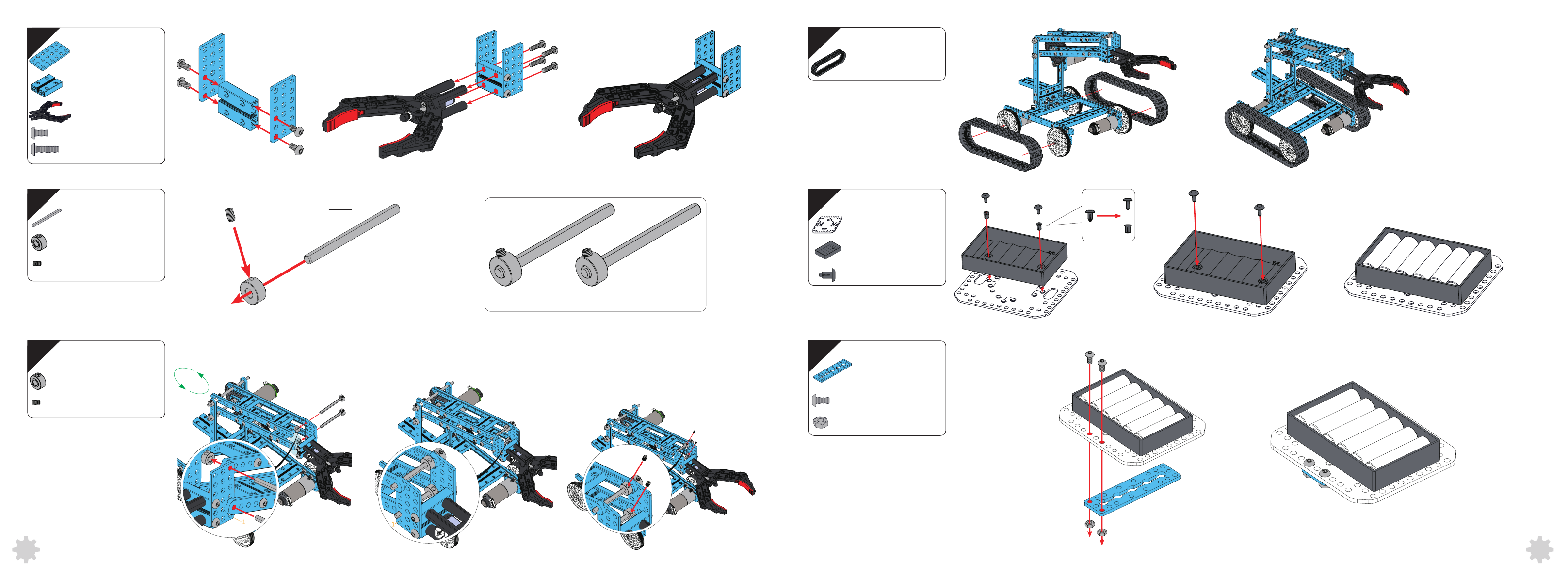
25
3×6
(2)
28
Track 80×139mm
(2)
26
27
0824-032
Makeblock Gripper
M4×8
M4×14
Shaft Collar
Headless Set
Screw M3×5
(1)
(1)
(4)
(4)
(2)D4×50
(2)
(2)
D Shaft D4×50mm
Note: Assemble two as shown.
29
30
MegaPi Acrylic
Bracket
Battery Holder
Plastic Rivet
4060
(1)
(1)
(2)
Shaft Collar
Headless Set
Screw M3×5
(2)
(2)
0324-088
M4×8
Nut M4
1
1
(1)
(2)
(2)
26 27
Page 2
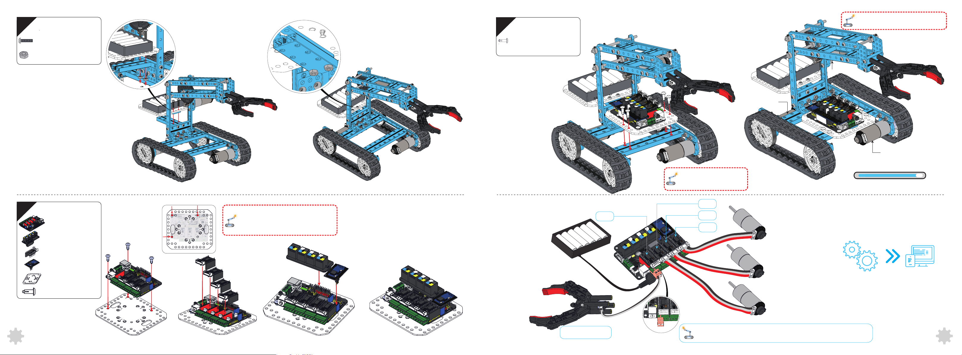
31
33
Assembled Diagram
NOTE:Please check whether the screw is
tightened according to the instruction.
32
M4×16
Nut M4
MegaPi
Shield for RJ25
(2)
(2)
(1)
(1)
To correctly assemble the main board onto
the acrylic bracket, please pay attention to
the direction of the arrow on the bracket.
Wiring
Plastic Rivet
4120
(4)
Motor C (86RPM)
Motor A (185RPM)
Motor B (185RPM)
You can also use the Screw
M4x14 to replace the rivet.
100%
You have now finished building the Robotic Arm Tank.
Port 3
Port 4
Port 2
Port 1
Motor A (185RPM)
28
Encoder/DC Motor
Driver
Bluetooth Module
MegaPi Acrylic
Bracket
Plastic Rivet 4100
(4)
(1)
(1)
(3)
Makeblock Gripper
Please connect the white and black wires with the sequence shown in the
image, then insert the plug to the 4B- and 4B+ port on mainboard.
Motor B (185RPM)
Motor C (86RPM)
After assembly, please skip to page 54 for
software instruction.
29
Page 3
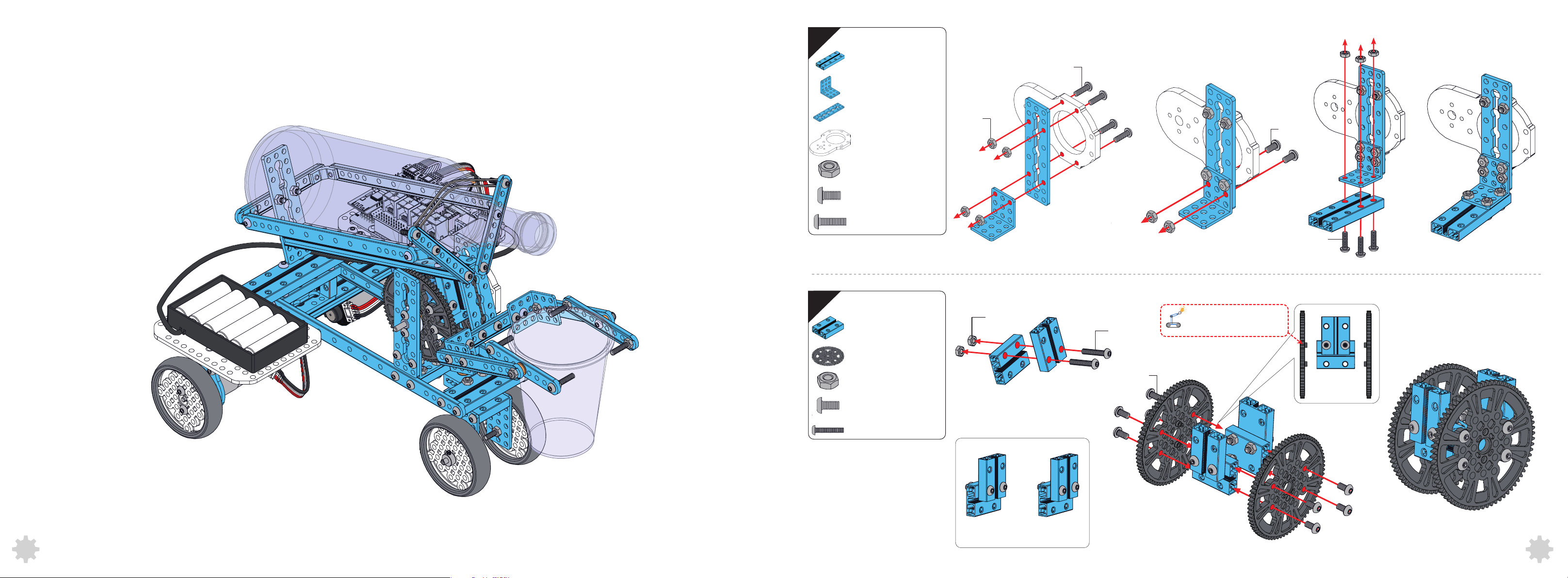
Beverage Robot
1
0824-064
(1)
M4×14
2
Bracket 3×3
0324-088
25mm Motor
Bracket-72T
Nut M4
M4×8
M4×14
0824-032
72T
(1)
(1)
(1)
(9)
(2)
(7)
(4)
(2)
Nut M4
Nut M4
M4×22
M4×8
M4×14
Pay attention to the
direction of the Gear 72T.
Nut M4
M4×8
M4×22
(4)
(8)
(4)
Note: Assemble two as shown.
M4×8
30 31
Page 4
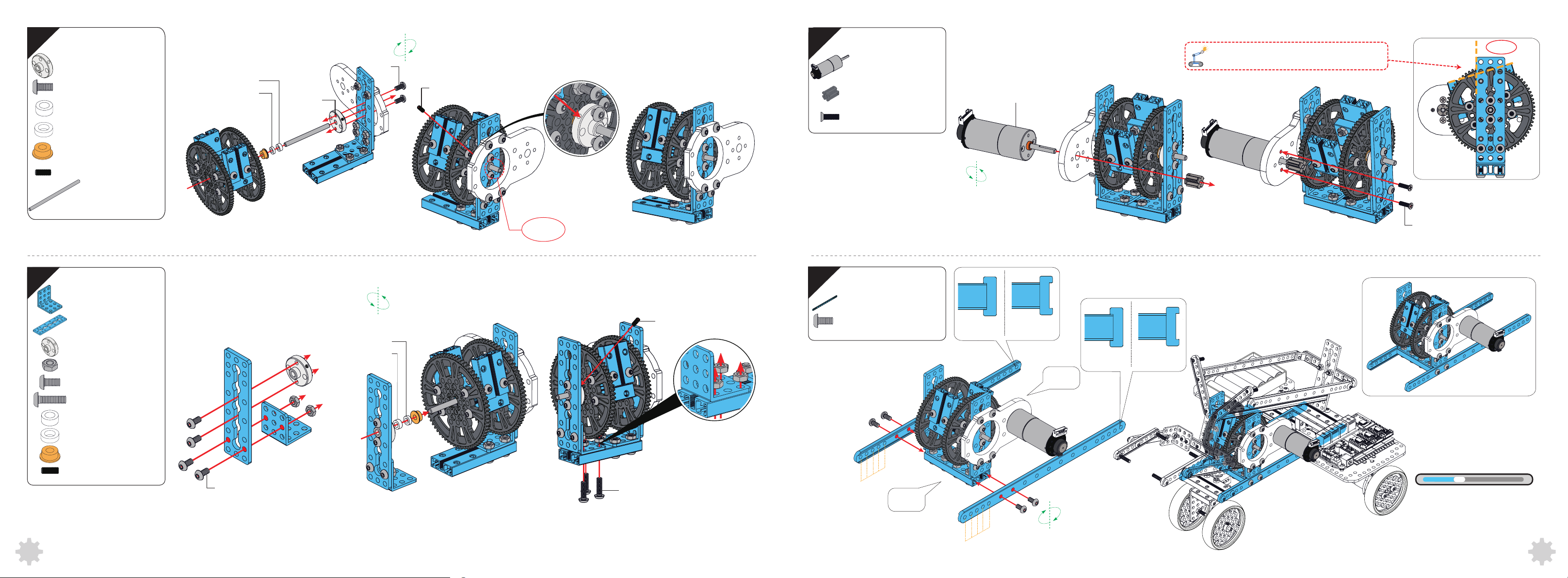
3
Shaft Connector
4mm
M4×8
Plastic Ring 4×7×3
Plastic Ring 4×7×2
(1)
(2)
(1)
(1)
Plastic Ring 4×7×3
Plastic Ring 4×7×2
Threaded
Hole
M4×8
M3×8
5
Encoder Motor
86RPM
Countersunk
M3×10
Screw
8T
(1)
(1)
(2)
Pay attention to the angle when assembling.
≈75°
Encoder Motor 86RPM
Flange Copper Sleeve
4
Plastic Ring 4×7×3
Headless Set
Screw M3×8
D4×88
Bracket 3×3
0324-088
Shaft Connector
4mm
Nut M4
M4×8
M4×14
(1)
(1)
(1)
(1)
(1)
(1)
(5)
(4)
(3)
(1)
Plastic Ring 4×7×2
Plastic Ring 4×7×3
≈10mm
M3×8
6
0412-220
M4×8
(2)
(4)
O
X
Back
O
M3×10
X
Plastic Ring 4×7×2
Flange Copper Sleeve
Headless Set
Screw M3×8
(1)
(1)
(1)
M4×8
M4×14
5
4
3
2
1
Front
5
4
3
2
1
25%
You have finished the
rotational structure.
32 33
Page 5
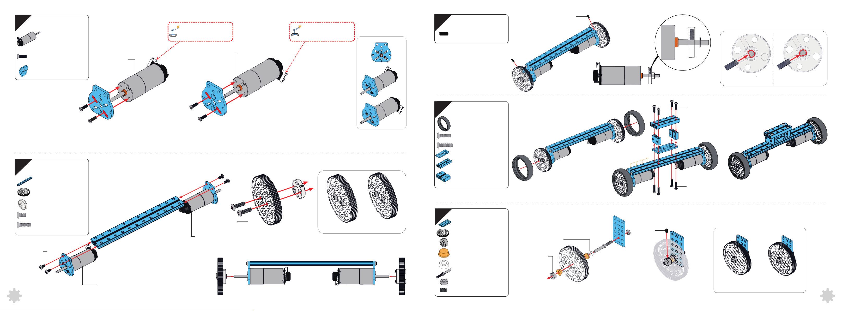
7
7
Encoder Motor
185RPM
(2)
Pay attention to direction
of the motor interface.
Pay attention to direction
of the motor interface.
9
Headless Set
Screw M3×8
M3×8
(2)
8
Countersunk
M3×8
Screw
25mm DC Motor
Bracket
0824-192
90T
Shaft Connector
4mm
M4×8
M4×14
M4×8
(4)
(2)
(1)
(2)
(2)
(4)
(4)
Encoder Motor
185RPM A
A
Encoder Motor 185RPM B
B
Encoder Motor 185RPM B
M4×14
B
Note: Assemble two as shown.
10
11
Tire 90T B
M4×14
M4×16
0324-056
0824-064
0824-016
3×6
90T
Shaft Collar
Flange Copper Sleeve
Plastic Ring 4×7×3
(2)
(4)
(4)
(1)
(1)
(2)
(2)
(2)
(2)
(4)
(2)
Plastic Ring 4×7×3
Shaft Collar
O
M4×14
4
3
2
1
M4×16
M3×5
X
A
Encoder Motor 185RPM A
34 35
4×39mm
Nut M4
Headless Set
Screw M3×5
(2)
(2)
(2)
Note: Assemble two as shown.
Page 6
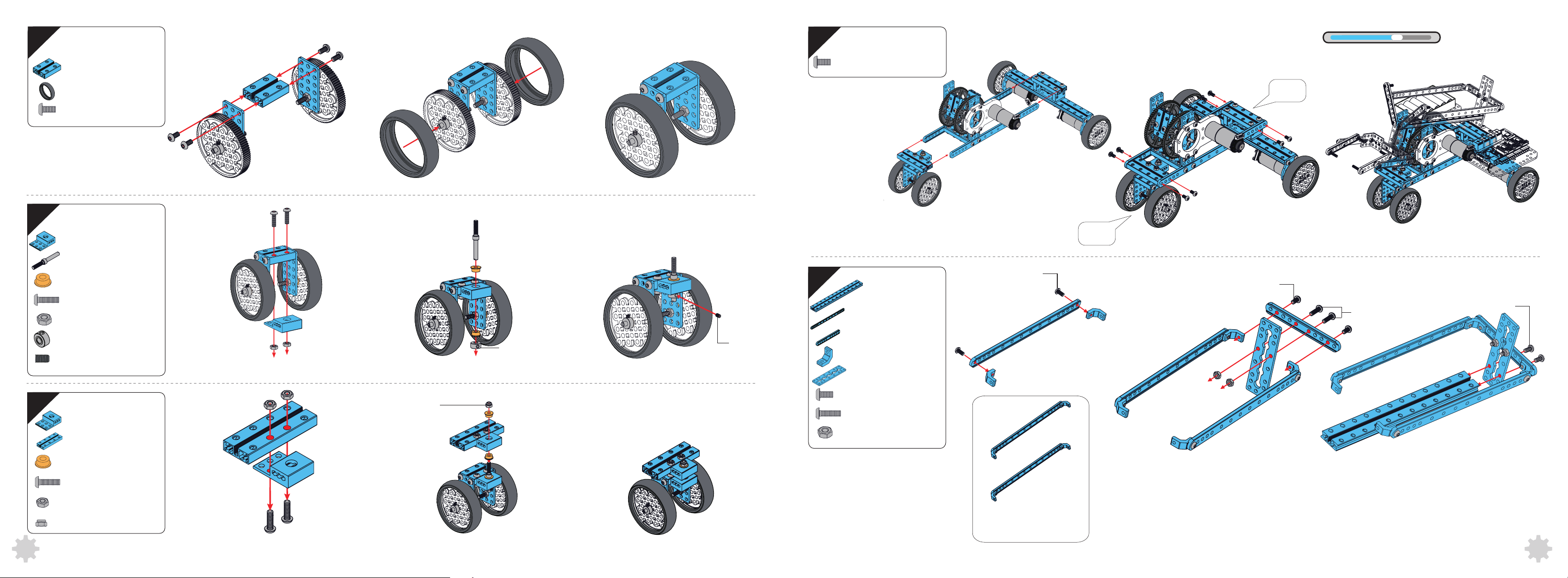
M4×8
12
0824-032
(1)
15
M4×8
(8)
65%
Now take a look at the cool things you have built.
13
Tire 90T B
M4×8
4×39mm
Flange Copper Sleeve
M4×14
Nut M4
Shaft Collar
Headless Set
Screw M3×5
P3
(2)
(4)
(1)
(1)
(2)
(2)
(2)
(1)
(1)
Shaft Collar
M3×5
16
0824-192
1616-08-M4
(1)
(2)0412-188
(1)0412-092
(4)
(1)0324-088
Front
M4×8
Back
M4×14
M4×8
14
0824-64
Flange Copper Sleeve
M4×14
Nut M4
Nylon Lock Nut M4
P3
(1)
(1)
(2)
(2)
(2)
(1)
M4×8
Nylon Lock Nut M4
M4×14
Nut M4
(8)
(2)
(2)
Note: Assemble two
as shown.
36 37
Page 7
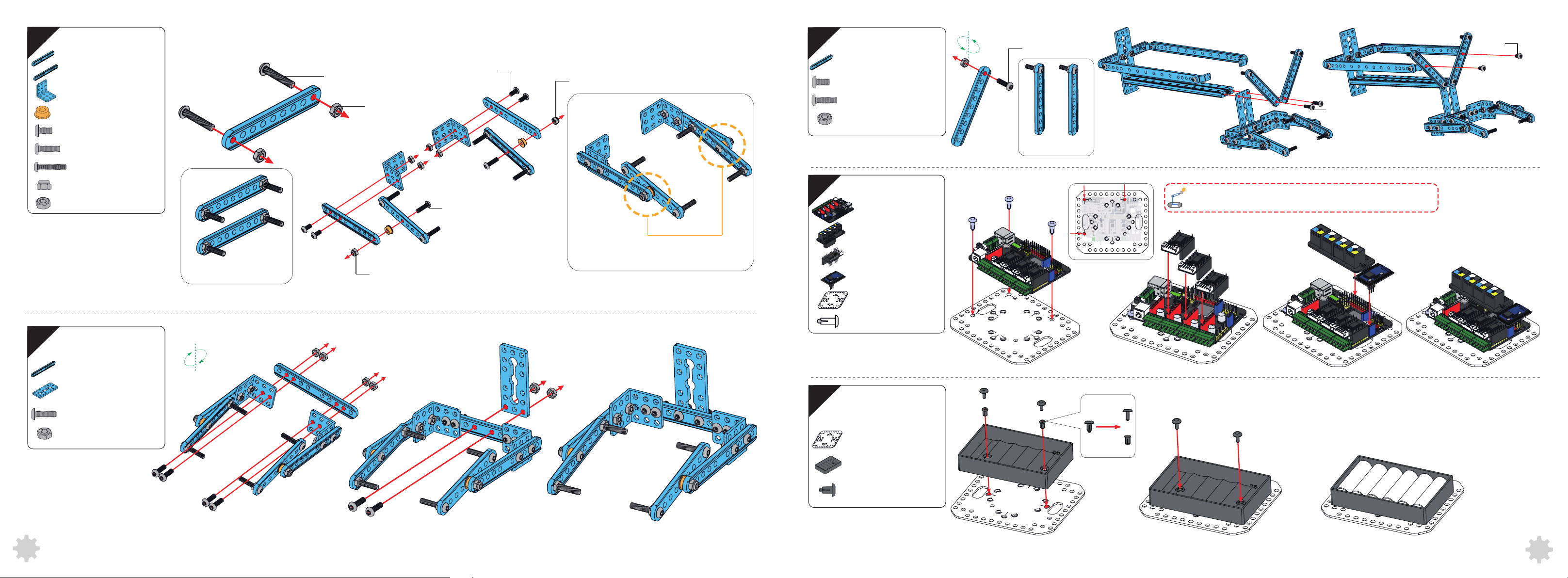
17
0412-076
Bracket 3×3
Flange Copper Sleeve
M4×8
M4×14
(2)
(2)0412-092
(2)
(2)
(4)
(2)
M4×22
Nut M4
M4×8
Nylon Lock Nut M4
19
M4×8
M4×14
Nut M4
(2)0412-076
(2)
(4)
(2)
M4×14
Note: Assemble two
as shown.
M4×8
M4×14
18
M4×22
Nylon Lock Nut M4
0412-092
0324-056
M4×14
Nut M4
(4)
(2)
(8)Nut M4
(1)
(1)
(6)
(6)
Note: Assemble two
as shown.
Nylon Lock Nut M4
M4×14
Note: Make sure this structure can rotate smoothly.
20
21
MegaPi
Shield for RJ25
Encoder/DC Motor
Driver
Bluetooth Module
MegaPi Acrylic
Bracket
Plastic Rivet 4100
MegaPi Acrylic
Bracket
To correctly assemble the main board onto the acrylic bracket,
(1)
(1)
(3)
(1)
(1)
(3)
(1)
please pay attention to the direction of the arrows on the bracket.
38
Battery Holder
Plastic Rivet
4060
(1)
(2)
39
Page 8
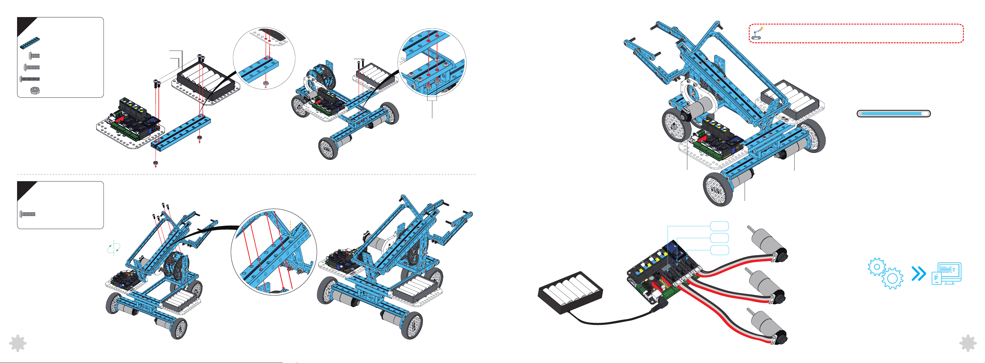
22
0824-128
M4×8
M4×14
(1)
(2)
(2)
M4×8
M4×14
Assembled Diagram
NOTE:Please check whether the screw is tightened according to the instruction. If the
beverage robot can’t work normally, please refer to FAQs for answers.
M4×22
23
M4×22
Nut M4
M4×14
(4)
(2)
(4)
100%
Nut M4
100% Completed!
Motor C (86RPM)
Motor A (185RPM)
Wiring
Motor B (185RPM)
1
Port 3
Port 2
Port 1
Motor A (185RPM)
40
Motor B (185RPM)
Motor C (86RPM)
After assembly, please skip to page 54 for
software instruction.
41
Page 9
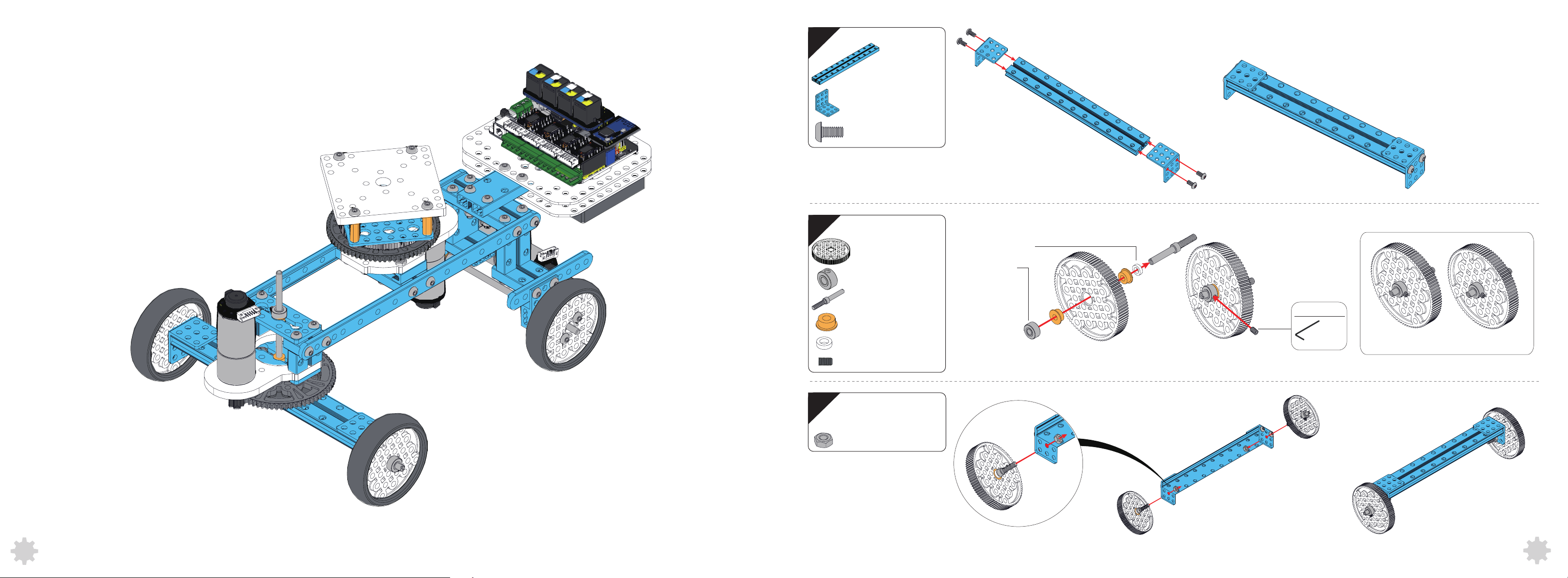
Camera Dolly
1
2
Flange Copper Sleeve
Plastic Ring 4×7×2
0824-176
Bracket 3×3
M4×8
90T
Shaft Collar
4×39mm
Headless Set
Screw M3×5
(1)
(2)
(4)
(2)
(2)
(2)
(4)
(2)
(2)
Plastic Ring 4x7x2
Flange Copper
Sleeve
tool
1.5mm
Note: Assemble two as shown.
42
3
Nut M4
(2)
43
Page 10
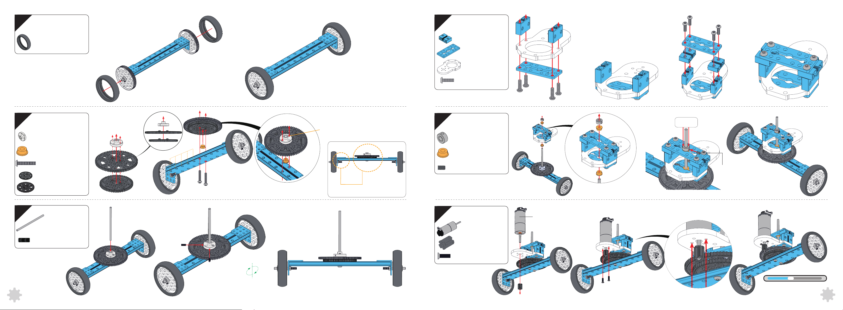
4
7
5
Shaft Connector 4mm
Flange Copper Sleeve
Tire 90T B
M4×22
56T
72T
(2)
(1)
(1)
(2)
(1)
(1)
0824-016
0324-056
25mm Motor
Bracket-72T
M4×16
8
Threaded Hole
Shaft Collar
5
4
3
2
1
Note: Pay attention to the direction
when assembling.
Flange Copper Sleeve
Headless Set
Screw M3×5
(4)
(2)
(1)
(8)
(1)
(2)
(1)
Pressure
M3x5
44
6
D4×88
Countersunk
M3×8
Screw
(1)
(2)
9
Encoder Motor
86RPM
Countersunk
M3×10
Screw
8T
(1)
(1)
(2)
Encoder Motor 86RPM
35%
You have finished
the first part.
45
Page 11
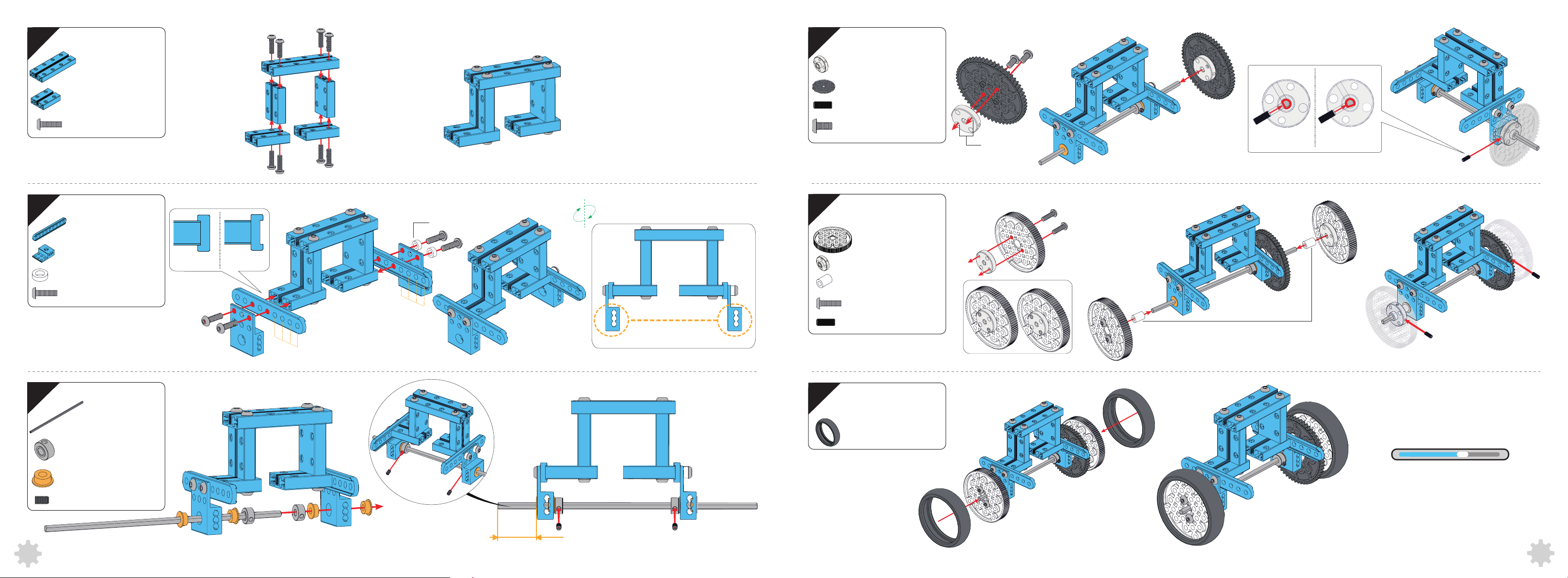
10
13
11
6
0824-64
0824-32
M4×14
0412-76
Plastic Ring 4×7×3
M4×14
P3
(1)
(4)
(8)
(2)
(2)
(2)
(4)
O
X
Shaft Connector
4mm
Headless Set
Screw M3×8
M4×8
56T
(1)
(1)
(1)
(2)
Threaded Hole
O
X
14
Plastic Ring 4x7x3
90T
(2)
Shaft Connector
4mm
Plastic Ring 4x7x10
4
3
2
1
4
3
2
1
11
Note: Please check the
direction of the P3 bracket.
M4×14
Headless Set
Screw M3×8
(2)
(2)
(4)
(2)
Plastic Ring 4x7x10
M3×8
46
666
12
D4×160
Shaft Collar
Flange Copper Sleeve
Headless Set
Screw M3×5
(1)
(2)
(4)
(2)
≈20mm
15
Tire 90T B
(2)
60%
Now take a look at the cool things
you have built.
47
 Loading...