


INSTALLER/CONSUMER SAFETY INFORMATION
PLEASE READ THIS MANUAL BEFORE INSTALLING AND USING APPLIANCE.
IMPORTANT: Read all instructions and warnings carefully before starting installation.
Failure to follow these instructions may result in a possible fire hazard and will void the warranty.
WARNING: If the information in this manual is not followed exactly, a fire or explosion may result causing property damage, personal injury or loss of life.
FOR YOUR SAFETY Installation and service must be performed by a qualified installer, service agency, or the gas supplier. Do not store or use gasoline or other flammable vapors and liquids in the vicinity of this or any other appliance.
FOR YOUR SAFETY
If you smell gas:
1.Open windows
2.Do not touch electrical switches.
3.Do not try to light any appliance.
4.Extinguish any open flame.
5.Do not use the phone in your building.
6.Immediately call your gas supplier from a neighbor's phone.
7.Follow your gas supplier's instructions.
8.If you cannot reach your gas supplier, call the fire department.
™
Decorative Gas Appliances
Models: NVBR36, NVBC36 |
|
NVBR42, NVBC42 |
|
NVBR36 |
|
NVBC42 |
950 |
|
|
Homeowner's Installation and |
||
DE |
GN |
Operating Manual |
|
|
SI |
|
|
|
|
|
C E RT I F I E D |
C |
|
D |
|
E |
|
|
|
|
RTIFIE |
|
|
Vermont Castings, Majestic Products
410 Admiral Blvd. • Mississauga, Ontario, Canada L5T 2N6 • 905-670-7777 www.majesticproducts.com • www.vermontcastings.com
INSTALLER: DO NOT DISCARD THIS MANUAL - Leave in fireplace for homeowner.
7412950 9/03 Rev. 12

Majestic Fireplaces® NVB Series B-Vent
Table of Contents
Thank you and Congratulations on your purchase of a
Vermont Castings, Majestic Products fireplace.
PLEASE READ THE INSTALLATION & OPERATING INSTRUCTIONS BEFORE USING THE APPLIANCE
IMPORTANT: Read all instructions and warnings carefully before starting installation. Failure to follow these instructions may result in a possible fire hazard and will void the warranty.
Installation & Operating Instructions ........................................................................................... |
3 |
General Information ........................................................................................................... |
3 |
Fireplace Dimensions ......................................................................................................... |
4 |
Clearance to Combustibles ................................................................................................ |
6 |
Mantels .............................................................................................................................. |
6 |
Mantel Chart ....................................................................................................................... |
6 |
Hearth .............................................................................................................................. |
6 |
Insulating for Cold Climates ............................................................................................... |
6 |
Framing & Finishing ........................................................................................................... |
7 |
Final Finishing .................................................................................................................... |
7 |
Gas Specifications ............................................................................................................. |
7 |
Gas Inlet & Manifold Pressures .......................................................................................... |
7 |
High Elevations .................................................................................................................. |
7 |
Parts Identification and Chase Installation ......................................................................... |
8 |
Gas Line Installation ........................................................................................................... |
8 |
Remote Wall Switch ........................................................................................................... |
9 |
EB-1 Electrical Box .......................................................................................................... |
10 |
Install the Venting System, Flashing, and Termination .................................................... |
10 |
Venting Runs .................................................................................................................... |
11 |
Operating Instructions |
|
Glass Information ............................................................................................................. |
12 |
Glass Cleaning ................................................................................................................. |
12 |
Log Installation ................................................................................................................. |
12 |
Ember Material Placement ............................................................................................... |
13 |
Lava Rock ........................................................................................................................ |
13 |
First Firing ........................................................................................................................ |
13 |
Flame Adjustment ............................................................................................................ |
13 |
Flame Characteristics ...................................................................................................... |
13 |
Inspecting the Venting System ......................................................................................... |
13 |
Lighting & Operating Instructions ..................................................................................... |
14 |
Troubleshooting ............................................................................................................... |
16 |
Maintenance ................................................................................................................................. |
18 |
Replacement Parts ....................................................................................................................... |
19 |
Optional Accessories .................................................................................................................. |
21 |
Warranty ....................................................................................................................................... |
22 |
2 |
7412950 |

Majestic Fireplaces® NVB Series B-Vent
General Information
This gas appliance should be installed by a qualified installer in accordance with local building codes and with current CSA-B149.1 Installation codes for Gas Burning Appliances and Equipment.
FOR U.S.A Installations follow local codes and/or the current National Fuel Gas Code. ANSI Z223.1.
FOR SAFE INSTALLATION AND OPERATION PLEASE NOTE THE FOLLOWING:
1.This appliance gives off high temperatures and should be located out of high traffic areas and away from furniture and draperies.
2.Children and adults should be alerted to the hazards of the high surface temperatures of this appliance and should stay away to avoid burns or ignition of clothing.
3.Children should be carefully supervised when they are in the same room as your appliance.
4.Under no circumstances should this appliance be modified. Parts having to be removed for servicing should be replaced prior to operating this appliance again.
5.Installation and any repairs to this appliance should be carried out by a qualified service person. A professional service person should be contacted to inspect this appliance annually. Make it a practice to have all of your gas appliances checked annually. More frequent cleaning may be required due to excess lint and dust from carpeting, bedding material, etc.
6.Control compartments, burners and air passages in this appliance should be kept clean and free of dust and lint. Make sure that the gas valve and pilot light are turned off before you attempt to clean this unit.
7.The venting system (chimney) of this appliance should be checked at least once a year and if needed your venting system should be cleaned.
8.Keep the area around your appliance clear of combustible materials, gasoline and other flammable vapour and liquids. This appliance should not be used as a drying rack for clothing, nor should Christmas stockings or decorations be hung in the area of it.
9.Under no circumstances should any solid fuels (wood, coal, paper or cardboard etc.) be used in this appliance.
10.The flow of combustion and ventilation air must not be obstructed in any way.
11.Whether the appliance is installed directly on carpeting, vinyl tile or any combustible material other than wood, this appliance must be installed on a metal or wood panel extending the full width and depth of the appliance.
12. This appliance requires adequate ventilation and combustion air to operate properly.
Description
NVB Series are radiant or heat circulating, natural draft appliances and use a 6" B-vent system. Do not burn wood or other materials in these appliances. Each model is available with standing pilot or electronic ignition for use with Natural or Propane gas units.
Report to your dealer any parts damaged in shipment.
Adequate combustion and ventilation air must be provided. The flow of combustion and ventilation air MUST NOT be obstructed.
Provide adequate clearances around the air opening into the combustion chamber; and adequate accessibility clearance for servicing and proper operation. NEVER obstruct the front opening of the appliance or cover the top and bottom louvres (grilles).
The 6" vent system MUST connect to the appliance and terminate out-of-doors in a vertical position and terminate with a B-vent cap.
This appliance must not be connected to a chimney flue servicing a separate solid-fuel burning appliance.
A draft hood is an integral part of the appliance.
Proposition 65 Warning: Fuels used in gas, woodburning or oil fired appliances, and the products of combustion of such fuels, contain chemicals known to the State of California to cause cancer, birth defects and other reproductive harm.
California Health & Safety Code Sec. 25249.6
IMPORTANT:
PLEASE READ THE FOLLOWING CAREFULLY
Remove any plastic from trim parts before turning the fireplace “ON”.
It is normal for fireplaces fabricated of steel to give off some expansion and/or contraction noises during the start up or cool down cycle. Similar noises are found with your furnace heat exchanger or car engine.
It is not unusual for your Vermont Castings, Majestic Products gas fireplace to give off some odor the first time it is burned. This is due to the curing of the paint and any undetected oil used in the manufacturing process.
Please ensure that your room is well ventilated. Open all windows.
It is recommended that you burn your fireplace for at least ten (10) continuous hours the first time you use it. If the optional fan kit has been installed, place the fan switch in the “OFF” position during this time.
7412950 |
3 |

Majestic Fireplaces® NVB Series B-Vent
|
|
|
|
|
NVBR36 Series Gas Appliance |
||
|
|
|
|
|
Rough |
|
22" (559mm) |
|
|
|
|
|
|
|
|
|
|
|
|
|
Opening |
|
|
|
|
45³⁄ " (1162mm) |
Depth |
8 ³⁄ " |
6" DIA. |
||
|
|
¹⁄ " (13mm) |
|
||||
|
|
20¹⁄ " |
(213mm) |
|
|||
|
|
|
|
|
|
||
|
|
|
|
|
(521mm) |
|
|
|
|
|
|
|
20" |
|
|
|
|
|
|
|
(508mm) |
⁄ " Recessed |
|
(1162mm) |
|
|
|
|
|
|
(16mm) Nailing |
|
32³⁄ " (822mm) |
(16mm) |
Rough |
Flange |
|||
|
|
||||||
|
|
(1041mm) |
|||||
|
|
|
"(1645mm) |
|
|
Rough Opening Width 41" |
|
|
|
|
" |
|
Opening |
|
|
³⁄" |
|
|
⁄ |
|
|
||
|
|
|
|
Height |
|
||
45 |
¹⁄ " |
|
|
|
|
|
|
|
|
64³⁄ |
|
|
|
|
7¹⁄ " |
|
|
|
|
|
|
|
|
|
|
|
|
|
|
|
(191mm) |
36" |
40¹⁄ " |
|
|
|
|
(914mm) |
|
|
|
|
|
(1029mm) |
|
|
|
|
|
|
|
19 ³⁄ " |
|
|
|
Outside |
|
|
|
|
|
Air |
7¹⁄ " |
36" |
(502mm) |
|
|
|
21" |
|
|
||
|
(191mm) |
(914mm) |
Gas Line |
||
|
(533mm) |
||||
|
|
|
Access |
|
|
|
14" |
|
|
|
|
Electrical |
|
7¹⁄ " |
|
|
|
Access |
(356mm) |
|
|
|
|
|
|
|
(191mm) |
|
|
13¹⁄ " |
3" |
40" |
|
6¹⁄ " |
3" |
(337mm) |
|
||||
|
(76mm) |
(1016mm) |
(165mm) |
(76mm) |
|
FP561
Fig. 1 NVBR36 Series specification and framing dimensions.
NVBC36 Series Gas Appliance — Circulating Model
|
Rough |
22" (559mm) |
|
|
|
|
Opening |
|
45³⁄ " (1162mm) |
Depth |
|
¹⁄ " (13mm) |
8 ³⁄ " |
|
20¹⁄ " (213mm) |
|
|
|
|
|
|
(521mm) |
|
|
20" |
|
|
(508mm) |
|
(1162mm) |
|
|
⁄ |
Opening |
(1041mm) |
|
|
|
" (16mm) |
Rough |
|
|
|
32³⁄ " (822mm) |
|
Rough Opening Width 41" |
|
|
|
|
(1645mm) |
|
|
" |
|
|
Height |
|
|
³⁄ |
|
" |
|
|
|
|
|
|
|
||
45 |
¹⁄ " |
|
|
|
|
64³⁄ |
|
|
|
||
|
|
|
|
|
|
36" |
40¹⁄ " |
|
(1029mm) |
|
|
(914mm) |
|
|
|
|
|
Outside |
|
36" |
Air |
7¹⁄ " |
|
|
(914mm) |
|
|
(191mm) |
|
|
|
|
Electrical |
14" |
|
Access |
(356mm) |
|
13¹⁄ " |
3" |
35¹⁄ " (902mm) |
(337mm) |
(76mm) |
40" (1016mm) |
Fig. 2 NVBC36 Series specification and framing dimensions.
6" DIA.
⁄ " Recessed
(16mm) Nailing
Flange
7¹⁄ " (191mm)
(502mm) |
(864mm) |
(533mm) |
Access |
|
³⁄19" |
34" |
21" |
|
|
|
|
|
Gas Line |
|
|
|
7¹⁄ " |
|
|
|
|
(191mm) |
|
|
|
2" |
|
6¹⁄ " |
3" |
(51mm) |
(165mm) |
(76mm) |
||
FP562
4 |
7412950 |

Majestic Fireplaces® NVB Series B-Vent
|
|
|
|
NVBR42 Series Gas Appliance |
|
|
|
|||
|
|
|
|
|
Rough |
|
28" (711mm) |
|
|
|
|
|
|
|
|
|
|
|
|
|
|
|
|
|
|
|
Opening |
|
|
|
|
|
|
|
49" (1245mm) |
Depth |
|
|
6" DIA. |
|
|
||
|
|
|
8 ³⁄ " |
|
|
|
||||
|
|
¹⁄ " (13mm) |
|
|
|
|
||||
|
|
20¹⁄ " |
|
|
|
|
||||
|
|
(213mm) |
|
|
|
|
||||
|
|
|
|
|
|
|
|
|
||
|
|
|
|
|
(521mm) |
|
|
|
|
|
|
|
|
|
|
|
20" |
|
|
|
|
|
|
|
|
|
(508mm) |
|
⁄ " Recessed |
|
||
(1245mm) |
|
|
|
|
|
|
|
(16mm) Nailing |
|
|
|
35¹⁄ " (895mm) |
(16mm) |
|
|
|
|
Flange |
|
||
|
|
|
Rough Opening Width 47" |
|
|
|
||||
|
|
|
|
|
|
|
|
|||
|
|
" |
Rough |
(1194mm) |
|
|
|
|||
|
|
Opening |
|
|
|
|
||||
|
⁄ |
|
|
|
|
|
||||
49" |
|
" |
(1765mm) |
Height |
|
|
|
|
||
¹⁄ " |
|
|
|
|
|
|
||||
69¹⁄ |
|
|
|
|
|
|
|
|
||
|
|
|
|
|
|
|
|
|
||
|
|
|
|
|
|
|
7¹⁄ " |
|
|
|
|
|
|
|
|
|
|
|
|
|
|
|
|
|
|
|
|
|
|
(191mm) |
|
|
|
|
36" |
|
40¹⁄ " |
|
|
|
|
||
|
|
|
(1029mm) |
|
21" |
|
|
|||
|
|
(914mm) |
|
|
|
|
||||
|
|
|
|
|
|
|
||||
|
|
Outside |
|
|
|
|
|
(533mm) |
|
|
|
|
|
|
7¹⁄ " |
42" |
19 ³⁄ " |
|
|
||
|
|
Air |
|
|
(191mm) |
(1067mm) |
(502mm) |
Gas Line |
||
|
|
|
|
|
||||||
|
|
|
|
|
|
14" |
|
|
Access |
|
|
|
Electrical |
|
|
|
|
7¹⁄ " |
|
|
|
|
|
Access |
|
|
(356mm) |
|
|
|
||
|
|
|
|
|
|
|
|
(191mm) |
|
|
|
|
|
|
13¹⁄ " |
3" |
|
46" |
|
6¹⁄ " |
3" |
|
|
|
|
(337mm) |
|
|
||||
|
|
|
|
|
(76mm) |
(1168mm) |
(165mm) |
(76mm) |
||
|
|
|
|
|
|
|
|
|
|
FP563 |
Fig. 3 |
NVBR42 Series specification and framing dimensions. |
|
|
|
|
|||||
|
|
NVBC42 Series Gas Appliance — Circulating Model |
|
|||||
|
|
49" (1245mm) |
8 ³⁄ " |
|
|
|
|
|
|
|
¹⁄ " (13mm) |
|
|
|
|
||
|
|
|
|
(213mm) |
|
|
|
|
(1245mm) |
|
|
"(16mm) |
|
|
|
|
|
|
|
⁄ |
|
|
|
|
|
|
|
|
(1765mm) |
|
|
|
|
|
|
49" |
¹⁄ " |
" |
|
|
|
|
|
|
|
69¹⁄ |
|
|
|
|
|
|
|
|
|
|
|
|
|
7¹⁄ " |
|
|
|
|
|
|
|
|
|
|
|
|
|
|
36" |
40¹⁄ " |
|
|
(191mm) |
|
|
|
|
|
|
|
|
||
|
|
(914mm) |
|
|
|
|
||
|
|
(1029mm) |
|
|
(533mm) |
|
||
|
|
|
|
|
(502mm) |
|
||
|
|
Outside |
|
|
|
|
||
|
|
Air |
|
7¹⁄ " |
42" |
|
||
|
|
|
|
Gas Line |
||||
|
|
|
|
(191mm) |
(1067mm) |
19³⁄" |
21" |
|
|
|
|
|
14" |
|
Access |
||
|
|
Electrical |
|
|
|
7¹⁄ " |
|
|
|
|
Access |
|
(356mm) |
|
|
|
|
|
|
|
|
|
|
|
(191mm) |
|
|
|
|
|
|
|
|
|
Rough |
|
|
|
|
|
|
|
|
Opening |
|
|
|
|
|
|
|
|
Depth |
|
|
|
13¹⁄ " |
3" |
|
|
|
6¹⁄ " |
|
|
|
(337mm |
46" (1168mm) |
|
|
||
|
|
|
|
(76mm) |
|
|
(165mm) |
|
|
|
|
|
|
|
|
|
FP564 |
Fig. 4 |
NVBC42 Series specification and framing dimensions. |
|
|
|
|
|||
7412950 |
|
|
|
|
|
|
5 |
|
RoughecessedOpening Width 47"

Majestic Fireplaces® NVB Series B-Vent
Clearance to Combustibles
Appliances |
|
Top .......................................................... |
0” (0mm) |
Bottom .................................................... |
0” (0mm) |
Side ........................................................ |
0” (0mm) |
Back ........................................................ |
0” (0mm) |
Perpendicular Sidewall ........................... |
0” (0mm) |
Top of unit to ceiling .......................... |
36” (914mm) |
Front of unit to combustibles ............ |
36” (914mm) |
Venting |
|
B-Vent ................................................... |
1” (25mm) |
Mantels\
The height that a combustible mantel is fitted above the fireplace is dependent on the depth of the mantel. This also applies to the distance between the mantel leg (if fitted) and the fireplace.
For the correct mounting height and widths refer to Figures 5a and 5b
The distances and reference points are not affected by the fitting of a bay window front trim kit.
Noncombustible mantels and legs may be installed at any height and width around the appliance.
When using paint or lacquer to finish the mantel, such paint or lacquer must be heat resistant to prevent discoloration.
V
Side View
W
X
Y
Z
A B C D E
Fireplace
|
|
|
|
|
|
|
|
Top of Combustion |
|
|
|
|
|
|
|
|
|
Chamber |
|
|
|
|
|
|
|
|
|
|
CFM146 |
|
|
|
|
|
|
|
|
|
|
|
|
|
|
|
|
|
|
||
Ref. |
|
Mantel |
|
Ref. |
|
|
Mantel From Top |
||
|
|
Shelf Depth |
|
|
|
|
of Comb. Chamber |
||
V |
|
14" (356mm) |
|
A |
|
|
18" (457mm) |
||
W |
|
12" (305mm) |
|
B |
|
|
16" (406mm) |
||
X |
|
10" (254mm) |
|
C |
|
|
14" (356mm) |
||
Y |
|
8" (203mm) |
|
D |
|
|
12" (305mm) |
||
Z |
|
1¹⁄ " (38mm) |
|
E |
|
|
8" (203mm) |
||
|
|
|
|
|
|
|
|
|
|
Fig. 5a |
Mantel clearances. |
|
|
|
|
|
|||
|
|
|
J |
I H |
|
|
|
|
|
|
|
|
|
G |
|
Black |
Mantel |
|
F |
|
Surround |
|
|
|
|
Leg |
|
|
|
|
Face |
|
|
|
CFM164 |
|
|
|
|
|
|
|
|
K |
|
Side of |
|
|
L |
|
|
|
M |
|
|
Combustion Chamber |
|
N |
|
|
|
|
O |
|
|
|
|
|
CFM170 |
Ref. |
Mantel |
Ref. |
Mantel Leg From |
|
|
Leg Depth |
|
of Comb. Opening |
|
F |
14" (356mm) |
K |
14" (356mm) |
|
G |
12" (305mm) |
L |
12" (305mm) |
|
H |
10" (254mm) |
M |
10" (254mm) |
|
I |
8" (203mm) |
N |
8" (203mm) |
|
J |
1¹⁄ " (38mm) |
O |
1¹⁄ " (38mm) |
|
Fig. 5b |
Combustible mantel leg minimum installation. |
|||
Hearth
A hearth is not mandatory but is recommended for aesthetic purposes. We recommend a noncombustible hearth.
Insulating For Cold Climates
When an appliance is installed in a chase or an outside wall, the enclosure should be insulated like any other wall of the home. Insulation should be installed under the appliance and on the inside of the exterior walls.
In a chase, it is a good idea to install a firestop at the first ceiling level above the appliance. Also, install insulation on the side walls. Insulation may then be placed above the ceiling to assure the space around the appliance is protected. Refer to Page 8, Figure 7.
6 |
7412950 |
Majestic Fireplaces® NVB Series B-Vent
Be sure to always maintain the proper one (1) inch distance to combustibles around B-vent pipe sections.
NOTE: Insulating for cold climates is strictly a recommendation and not a requirement.
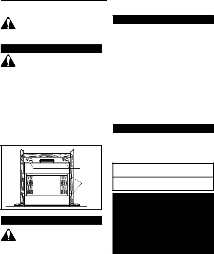
Framing and Finishing
Check appliance to make sure it is levelled and properly positioned.
The appliance should only be mounted on the following surfaces:
•A flat combustible (burnable) surface.
•A raised wooden platform.
•A concrete block or other solid object placed beneath each of the four corners of the appliance.
To mount the appliance:
1.Choose unit location.
2.Four (4) nailing flanges are supplied with the fireplace (found on the fireplace hearth). To level the box and secure it firmly in place, remove the nailing flanges from the hearth and install at the sides of the fireplace as shown in Figure 6.
Nail Top |
Standoffs |
Nail Side- |
Nailing |
Flanges |
FP549 |
Fig. 6 Adjustable drywall strip (nailing flange).
Finishing
CAUTION: All joints between the finished wall and the appliance surround (top and
sides) may be sealed only with noncombustible material. Only noncombustible material can be applied as facing to the appliance surround (the black painted face).
When finishing the appliance, never obstruct or modify the air inlet/outlet grilles in any manner.
Finish the wall with the material of your choice. Refer to Figures 5a and 5b for specific clearances when installing a combustible mantel or other combustible projection.
Gas Specification
|
|
|
Max. |
Min. |
Model |
Fuel |
Gas Control |
Input |
Input |
NVBR36RN |
Natural |
Millivolt Hi/Lo |
30,000 |
21,500 |
NVBC36RN |
Natural |
Millivolt Hi/Lo |
30,000 |
21,500 |
NVBR36RP |
Propane |
Millivolt Hi/Lo |
30,000 |
22,000 |
NVBC36RP |
Propane |
Millivolt Hi/Lo |
30,000 |
22,000 |
NVBR36EN |
Natural |
Electronic Ignition |
30,000 |
21,500 |
NVBC36EN |
Natural |
Electronic Ignition |
30,000 |
21,500 |
NVBR36EP |
Propane |
Electronic Ignition |
30,000 |
22,000 |
NVBC36EP |
Propane |
Electronic Ignition |
30,000 |
22,000 |
NVBR42RN |
Natural |
Millivolt Hi/Lo |
30,000 |
21,500 |
NVBC42RN |
Natural |
Millivolt Hi/Lo |
30,000 |
21,500 |
NVBR42RP |
Propane |
MIllivolt Hi/Lo |
30,000 |
21,500 |
NVBC42RP |
Propane |
Millivolt Hi/Lo |
30,000 |
21,500 |
NVBR42EN |
Natural |
Electronic Ignition |
30,000 |
21,500 |
NVBC42EN |
Natural |
Electronic Ignition |
30,000 |
21,500 |
NVBR42EP |
Propane |
Electronic Ignition |
30,000 |
22,000 |
NVBC42EP |
Propane |
Electronic Ignition |
30,000 |
22,000 |
Gas Inlet & Manifold Pressures
|
|
|
|
Natural |
LP |
Minimum Inlet Pressure |
5.5” w.c. |
11.0” w.c. |
Maximum Inlet Pressure |
14.0” w.c. |
14.0” w.c. |
Manifold Pressure |
3.5”w.c. |
10.0” w.c. |
|
|
|
NVBR36 / NVBC36 / NVBC42 / NVBR42 Certified to
ANSI Z21.50a-1999/CSA 2.22A-M-99
Vented Gas Fireplace
High Elevations
Input ratings are shown in BTU per hour and are certified without deration for elevations up to 4,500 feet (1,370m) above sea level.
For elevations above 4,500 feet (1,370m) in USA, installations must be in accordance with the current ANSI Z223.1 and/or local codes having jurisdiction.
In Canada, please consult provincial and/or local authorities having jurisdiction for installations at elevations above 4,500 feet (1,370m).
7412950 |
7 |

Majestic Fireplaces® NVB Series B-Vent
Parts Identification and Chase Installation
(Insulation methods shown are optional for cold climate, not a requirement for unit operation.)
Batt Insulation (cut out around firestop)
Firestop
Ceiling Level
Nailing Flange
Electrical
Access
Outside Air
Cover Plate
Termination Cap
Storm Collar
 Pan Flashing
 Draftstop
*Do not install header until unit is in place. See Page 8, "Mounting the Appliance."
Standoff

 Surround
Screen
Grate
Firebox
FP597
Fig. 7 Parts identification and system installation.
Gas Line Installation
This appliance must be isolated from the gas supply piping system by closing its individual manual shut off valve during any pressure equal to or less than 1/2 psig (3.45 kPa).
The appliance and its individual shutoff valve must be disconnected from the gas supply piping system during any pressure testing of that system at test pressures in excess of 1/2 psig (3.45 kPa).
If gas piping from the source to the appliance location has not been accomplished, install the required pipe. Consult local plumbing code to assure proper pipe size.
The gas pipeline can be brought in through the right side of the appliance. A knockout is provided to allow for the gas pipe installation and testing of any gas connection. It is most convenient to bring the gas line in from the right side, as this allows fan installation or removal without disconnecting the gas line.
NOTE: The gas line connection can be made with 3/8" copper tubing approved for propane or natural gas, 1/2" rigid pipe or an approved flex connector, then reduced to 3/8" to the appliance. Because some municipalities have some additional local codes, it is always best to consult your local authority.
8 |
7412950 |
 Loading...