

Majestic Appliances HE32EF User Manual
Electric
Fireplace
Model
HE32EF
Installation Instructions & Homeowner's Manual
WARNING! IF THE INFORMATION IN THIS MANUAL IS NOT FOLLOWED EXACTLY,
AN ELECTRICAL SHOCK OR FIRE MAY RESULT CAUSING PROPERTY DAMAGE,
PERSONAL INJURY OR LOSS OF LIFE.
FOR YOUR SAFETY
DO NOT STORE OR USE GASOLINE OR OTHER
FLAMMABLE VAPOURS OR LIQUIDS IN THE VICINITY
C US
Majestic Products Company
410 Admiral Blvd. • Mississauga, Ontario • Canada L5T 2N6
www.vermontcastings.com • www.majesticproducts.com
INSTALLER: DO NOT DISCARD THIS MANUAL - LEAVE FOR HOMEOWNER
OF THIS OR ANY OTHER APPLIANCE.
The Vermont Castings
- 1 -
™
10003395
07/01 Rev.0

TABLE OF CONTENTS
Please read the Installation & Operating Instructions before using this appliance.
Thank you and congratulations on your purchase of a Vermont Castings Majestic Products Company fireplace.
IMPORTANT: Read all instructions and warnings carefully before starting installation. Failure to follow these instructions
may result in a possible electric shock, fire hazard and/or injury and will void the warranty.
Installation Instructions ........................................................................................................... 3
General Information .................................................................................................... 3
Locating your Fireplace............................................................................................... 3
Electrical Specifications .............................................................................................. 3
Fireplace Dimensions.................................................................................................. 4
Mantels ................................................................................................................ 5
Framing & Finishing .................................................................................................... 5
Clearance to Combustibles ......................................................................................... 5
Final Finishing ............................................................................................................. 5
Hearth ................................................................................................................ 5
Electrical Connection .................................................................................................. 6
Installation of Logs ...................................................................................................... 6
Ceramic Refractory ..................................................................................................... 6
Service Instructions ................................................................................................................. 7
Louvre Removal .......................................................................................................... 7
Glass Frame Removal ................................................................................................ 7
Glass Information ........................................................................................................ 7
Replacing Light Bulbs ................................................................................................. 7
Maintenance of Motors................................................................................................ 8
Cleaning Brass Trim.................................................................................................... 8
Electrical Diagram ....................................................................................................... 8
Operating Instructions ............................................................................................................. 9
On/Off Switch .............................................................................................................. 9
Heater Control............................................................................................................. 9
Log Illumination Control .............................................................................................. 9
Flame Speed Control .................................................................................................. 9
Control Panel .............................................................................................................. 9
Replacement Parts Pictorial .................................................................................................. 10
Replacement Parts List ............................................................................................. 11
Fan Heater Installation ........ .................................................................................................. 12
Trim Options ........................................................................................................................... 13
1) Flat Surround ....................................................................................................... 13
2) Beveled Surround ................................................................................................ 15
3) Louvre Kits ........................................................................................................... 16
4) Bay Window Trim................................................................................................. 18
5) Cast Trim ............................................................................................................. 21
5) Accessories Options ............................................................................................ 21
- 2 -
INSTALLATION INSTRUCTIONS
GENERAL
1 . Read all instructions before using this appliance.
2. This appliance is hot when in use. To avoid burns, do
not let bare skin touch hot surfaces. If provided, use
handles when moving this appliance. Keep combustible materials, such as furniture, pillows, bedding,
papers, clothes and curtains at least 3 feet (1m) from
the front of this appliance.
3. CAUTION: Extreme caution is necessary when any
heater is used by or near children or invalids and
whenever the heater is left operating and unattended.
4. If possible, always unplug this appliance when not in
use.
5. Do not operate any heater with a damaged cord or plug
or after the appliance malfunctions, or if it has been
dropped or damaged in any manner.
6. Any repairs to this fireplace should be carried out by a
qualified service person.
15.To prevent a possible fire, do not block air intakes or
exhaust in any manner. Do not use on soft surfaces,
like a bed, where openings may become blocked.
16.This appliance has hot and arcing or sparking parts
inside. Do not use it in areas where gasoline, paint or
flammable liquids are used or stored. This fireplace
should not be used as a drying rack for clothing, nor
should Christmas stockings or decorations be hung in
the area of it.
17.Use this appliance only as described in this manual.
Any other use not recommended by the manufacturer
may cause fire, electric shock or injury to persons.
18.Avoid the use of an extension cord because the
extension cord may overheat and cause a risk of fire.
However, if you have to use an extension cord, the
cord shall be No. 16 AWG minimum size and rated not
less than 2025 Watts. The extension cord must be a
three wire cord with grounding type plug and cord
connection.
7. Under no circumstances should this fireplace be modified. Parts having to be removed for servicing must be
replaced prior to operating this fireplace again.
8. Do not use outdoors.
9. This heater is not intended for use in bathrooms,
laundry areas and similar indoor locations. Never
locate this appliance where it may fall into a bathtub or
other water container.
10.Do not run cord under carpeting. Do not cover cord
with throw rugs, runners or the like. Arrange cord away
from traffic areas and where it will not be tripped over.
11.To disconnect this appliance, turn controls to the off
position, then remove plug from outlet.
12.Connect to properly grounded outlets only.
13. This appliance, when installed must be electrically
grounded in accordance with local codes or, in the
absence of local codes, with the current CSA C22.1
Canadian Electrical Code or for U.S.A. installations
follow local codes and the National Electrical Code,
ANSI/NFPA NO. 70.
14. Do not insert or allow foreign objects to enter any
ventilation or exhaust opening as this may cause an
electric shock or fire, or damage the appliance.
19. SAVE THESE INSTRUCTIONS.
LOCATING YOUR VERMONT CASTINGS
MAJESTIC PRODUCTS COMPANY
ELECTRIC FIREPLACE
Your new fireplace may be installed into an existing
masonry fireplace. This unit may also be built into new
or existing construction.
When choosing a location for your new fireplace, ensure
that the general instructions are followed. Also, for best
effect install the fireplace out of direct sunlight.
A zero clearance kit is NOT required
for this unit.
ELECTRICAL SPECIFICATIONS
Voltage _____________ 120VAC, 60Hz
Total Amps ______________12.5 Amps
Total Watts _____________ 1500 Watts
Heater Rating ___________ 1300 Watts
- 3 -
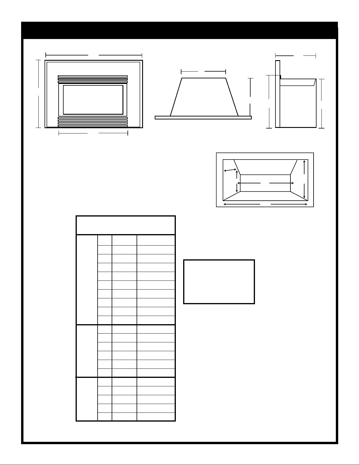
FIREPLACE DIMENSIONS
B
F
D
A
E
G
H
C
MINIMUM FIREPLACE OPENING
T
U
S
Q
R
R - Fireplace opening width
HE32EF
A1 26
B1 38
5/8"
3/8"
676 mm
975 mm
Q - Fireplace opening height
S - Firebox width at depth(T)
T - Firebox depth at back height (U)
U - Height at depth
A2 29" 737 mm
T
B2 41
R
I
A3 33" 838 mm
M
B3 44" 1118 mm
A4 28" 712 mm
B4 40
A5 30
15/16"
7/8"
1/2"
1065 mm
1041 mm
775 mm
1= SS or SSD Trim
2= SL or SLD Trim
3= SXL Trim
4= BSL Trim
5= BXL Trim
B5 46" 1171 mm
F
C 28
I
D 18
R
E
E 11
P
F 13" 330 mm
L
A
G 22" 558 mm
C
H 20" 508 mm
E
M
I
N
I
M
U
M
Q 21" 533 mm
O
P
R 28" 711 mm
E
S 19" 433 mm
N
I
T 11
N
U 20
G
3/4"
3/4"
1/2"
3/4"
1/4"
730 mm
476 mm
292 mm
289 mm
514 mm
Fig. 1
- 4 -
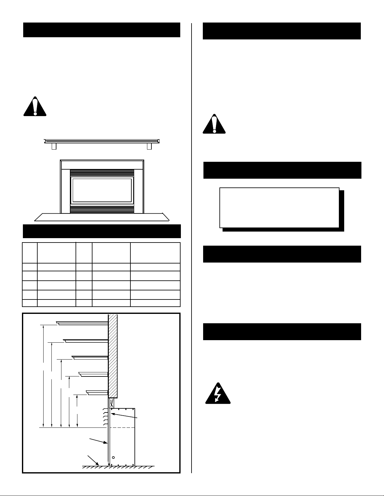
MANTELS
When the fireplace is being installed into a woodburning
fireplace the minimum the mantel can be above the fireplace is governed by local building codes applicable to
woodburning fireplaces. Consult local authorities having
jurisdiction for these clearances.
FRAMING & FINISHING
Before deciding on the frame dimensions and finishing
materials it is important to consider the finished dimensions
of the chosen fireplace trim kit (see options section of this
manual).
The underside of the mantel will get quite
warm. Use only finishes which are heat
resistant and do not discolour.
The fitting of the bay window kit does not
affect the dimensions or reference points in
the mantel chart.
RAISED
24" MIN.
Fig. 2
MANTEL CHART
Ref. Mantel & Leg Ref. Mantel From Mantel Leg from
Shelf Depth Top of Comb. From Side of Comb.
V 10" (254 mm) A 19" (305 mm) 10" (254mm)
W 8" (203 mm) B 17" (254 mm) 8" (203mm)
X 6" (152 mm) C 15" (203 mm) 6" (152mm)
Y 4" (101 mm) D 13" (152 mm) 4" (101mm)
Z 2" ( 51 mm) E 11" (101 mm) 2" (51mm)
Chamber Chamber
This information is required at this stage to ensure a
satisfactory finish when the trim kit is installed.
The use of wall paper adjacent to this fireplace
is not recommended, as the high heat given off
by this fireplace may adversely effect the binders in the adhesive used to apply the wallpa-
per.
610mm
CLEARANCE TO COMBUSTIBLES
Sides ....... 0 mm/0 inches
Sides ....... 0mm/0 inches
Floor........ 0 mm/0 inches
Top.......... 0 mm/0 inches
FINAL FINISHING
Non-combustible materials such as brick and tile can be
extended over the face of the unit (Do not cover louvres
or glass door). If a Trim Kit is going to be installed, brick
and tile will have to be installed flush with the side of this
appliance.
A
B
C
FIREBOX TOP
D
E
FRONT
GLASS
OPTIONAL
HEARTH
V
W
X
WALL
Y
A hearth is not mandatory but it is recommended for
aesthetic purposes. We recommend a non-combustible
hearth which does not obstruct louvre opening.
HEARTH
Cold climate installation recommendation:
Z
When installing this unit against a noninsulated exterior wall or chase, it is
mandatory that the outer walls be insulated
to conform to applicable insulation codes.
FIREPLACE
SIDE VIEW
TOP
LOUVRE
OPENING
Fig. 3
- 5 -
ELECTRICAL CONNECTION
INSTALLATION OF LOGS
A 15 AMP, 120 Volt, 60 Hz circuit with a properly grounded
outlet is required. Preferably, the fireplace will be on a
dedicated circuit as other appliances on the same circuit
may cause the circuit breaker to trip or the fuse to blow
when the heater is in operation. The unit comes standard
with a 6 ft. (1828mm) long three wire cord, exiting the right
side of the fireplace. Plan the installation to avoid the use
of an extension cord. If an extension cord must be used,
it must be a minimum 16AWG, three wire with grounding
type plug and connector and rated not less than 2025
Watts.
A new electrical outlet can be installed inside the frame
construciton, if permitted by local codes.
Electrical outlet wiring must comply with
local building codes and other applicable
regulations to reduce the risk of fire, electrical
shock and injury to persons.
Do not use this fireplace if any part of it has
been under water. Immediately call a
qualified service technician to inspect the
fireplace and replace any part of the electrical
system which has been under water.
1. Turn off power to the unit.
2. Remove front glass (See "Glass Removal" section).
3. The log bottom is shipped in place. No adjustment is
necessary.
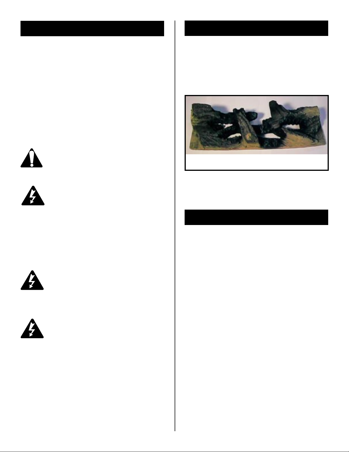
HE32EF / DEF33 *
* HE32EF / DEF33 is a unitized log set.
Fig. 4
CERAMIC REFRACTORY INSTALLATION
Hard (Direct) Wire Connection
If desired, a qualified electrician may remove the cord
conection and wire this unit directly to the household
wiring.
Any electrical re-wiring of this appliance
must be done by a qualified electrician.
WARNING: This fireplace comes with an
optional manual circuit breaker reset beside
the On/Off switch. In case the fireplace is
not operating check the circuit breaker and
reset the button at the breaker. If the
fireplace is still not operating immediately
call a qualified service technician to inspect
the fireplace.
1. Remove the glass assembly.
2. Slide refractory panels on either side of the firebox
between firebox side and the upper lintel baffle.
3. Push panels against firebox side. If desired, secure
the panels to the sides of the firebox with some
adhesive, such as silicone.
4. Replace glass frame and upper louvre panel.
- 6 -
SERVICE INSTRUCTIONS
Disconnect power before attempting any
maintenance or cleaning to reduce the risk
of fire, electrical shock or personal injury.
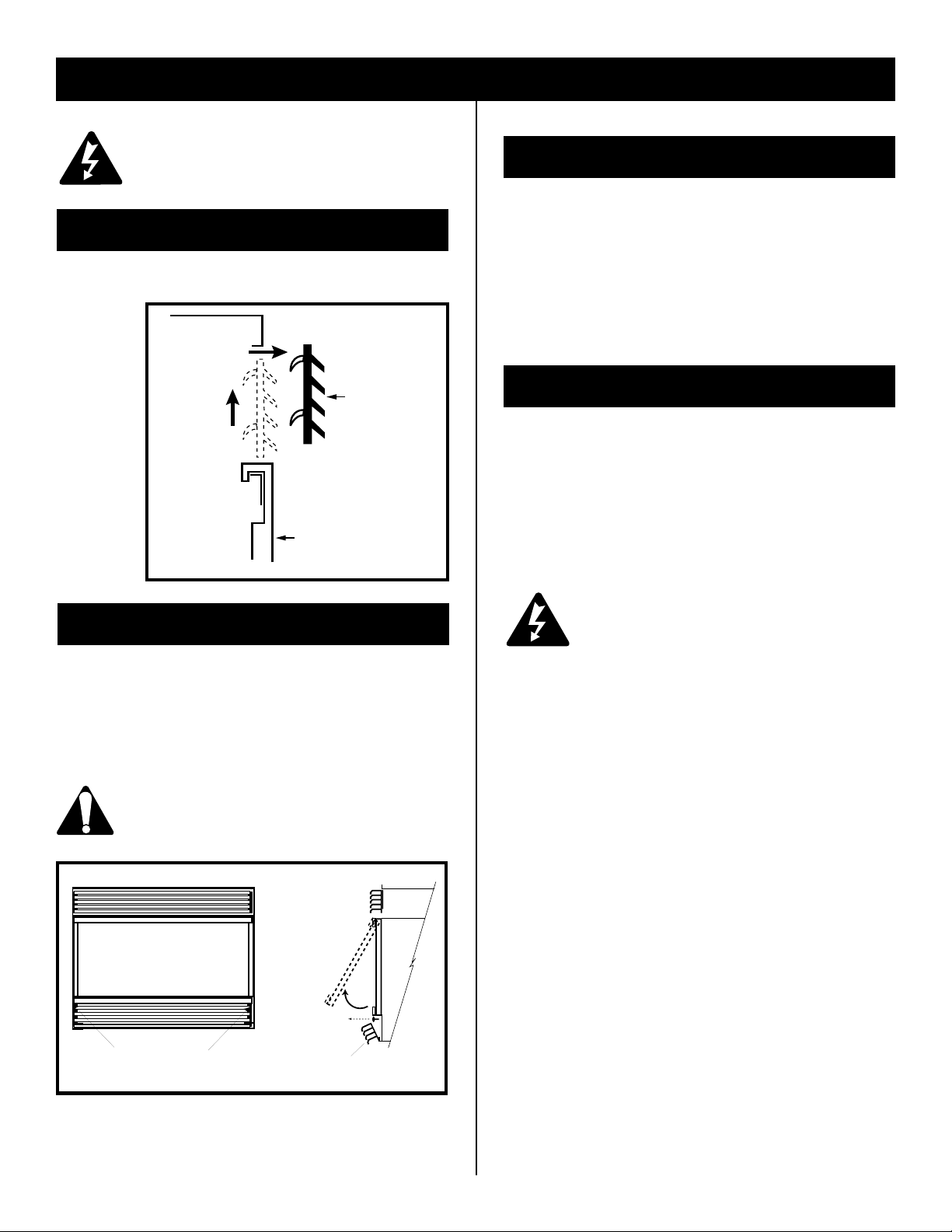
LOUVRE REMOVAL
To remove top louvre pull louvre up and then lift out.
See Figure 5.
2.
GLASS INFORMATION
1. Under no circumstances should this product be
operated with missing or broken glass.
2. Do not strike or slam the glass.
3. Do not use abrasive cleaners to clean the glass.
4. This product uses tempered glass. Replacement of
the glass with gasket as supplied by the manufacturer should be done by a qualified service person.
LOUVRE
1.
GLASS
PANEL
Fig. 5
GLASS FRAME REMOVAL
1
. Remove the top louvre. (See "Louvre Removal" section)
2. Open the access door.
3. Remove two machine screws from the bottom of glass
frame.
4. Lift up and unhook glass frame at the top.
Before remounting glass frame, brass trim
must be installed. See instructions in
"Frame Mounting" section.
GLASS FRAME
REPLACING LIGHT BULBS
This fireplace uses three (3) clear 120 Volt, 60 Watt, E12 and one (1) clear 120 Volt, 5 Watt, E-12 socket base
light bulbs. (Small base, chandelier candle type). Three
(3) of the lights are located under the ember bed of the
unit. The fourth (4) light is found at the top of the firebox
above the log set. For convenience, if one of the bulbs
burns out, it may be a good idea to replace all of the light
bulbs.
Do not exceed 60 Watts per bulb. Use of
higher rated bulbs may result in a fire,
causing property damage, personal injury
or loss of life.
1. Turn off power to the unit.
2. Let fireplace cool if it has been operating.
3. Remove top louvre. (See Louvre Removal).
4. Remove glass door. (See Glass Frame Removal).
5. Remove the two screws securing the ember bed in
position. One screw is located on either side of the
ember bed near the front.
6. Examine the bulbs to determine which bulbs need to
be replaced.
7. While holding the socket, unscrew the defective
bulb(s).
8. Install the new light bulb(s) by screwing in while
holding the socket.
9. Reinstall ember bed, log set, glass door and top
louvre.
MACHINE SCREWS
SCREWS
OPEN ACCESS DOOR
Fig. 6
- 7 -
 Loading...