


IW7 WB
IW4 WB / WBV
IW7 WB / WBV
Roller Brake Tester
for vans and trucks up to 13t / 18t axle load
Standard Operating Procedures
and User’s Manual
English
D1 0412BA1-GB04

IW4/IW7 WB/WBV
EDITION
Version 4 of the operations manual dated 2005-08-08
D1 0412BA1 GB04
Software Version 1.43
Software Version 1.44 / MB
Software Version 1.45 / Portugal
Software Version 1.46 / Deutschland
Software Version 1.48 / Hongkong
© MAHA GMBH & CO. KG.
All rights reserved. Any reproductions of this document, partial or complete, are only allowed
with prior consent of MAHA GmbH & Co. KG.
All rights reserved in cases of patent granting or registration of design.
The contents of this version have been checked with great care. However, errors cannot be fully
excluded. Please contact MAHA should you find errors of any kind.
Subject to technical change without notice.
These instructions are intended for users with previous technical knowledge in the field of
vehicle testing technology as well as basic computer knowledge and MS-Windows operating
system application.
Windows and Windows for Workgroups is a registered trademark of the Microsoft-Corporation.
MANUFACTURER
MAHA Maschinenbau Haldenwang GmbH & Co. KG.
Hoyen 20
D-87490 Haldenwang/Allgäu
Telephone: 08374 / 585-0
Telefax: 08374/ 585-499
Internet: http://www.maha.de
e-mail: maha@maha.de
SERVICE
MAHA Maschinenbau Haldenwang GmbH & Co. KG.
- Service dept. Hoyen 20
D-87490 Haldenwang/Allgäu
Hotline: 0180 56242 + extension
60 for brake testers, test lanes
80 for lifting technology
90 for performance testers, exhaust and air conditioning service equipment
Service: 0180 5624250
Telefax: 0180 5624255
II D1 0412BA1-GB04

IW4/IW7 WB/WBV
TABLE OF CONTENTS
1 Description.................................................................................................................1
1.1 Introduction.....................................................................................................................................1
1.2 General Information about Brake Testing......................................................................................1
1.2.1
Vehicle with a Driven Axle ..............................................................................................2
1.2.2
4-Wheel Drive Vehicle....................................................................................................2
1.3 Technical Data ...............................................................................................................................5
1.3.1
Electrical Data.................................................................................................................5
1.3.2
Mechanical Data.............................................................................................................6
1.3.3
Electronic........................................................................................................................7
1.4 Standard Equipment IW4/IW7 WB/WBV (4WD) ...........................................................................7
1.5 Noise Emission ..............................................................................................................................7
1.6 Equipment IW7 MB Version...........................................................................................................8
2 Safety..........................................................................................................................9
2.1 Introduction.....................................................................................................................................9
2.2 Safety Regulations for Commissioning ........................................................................................10
2.3 Safety Regulations during Operation ...........................................................................................10
2.4 Safety Regulations for Service Work ...........................................................................................10
2.5 Attention.......................................................................................................................................11
2.6 Further Information.......................................................................................................................11
2.7 Combination with Accessories .....................................................................................................11
2.8 Exchange of Parts........................................................................................................................11
2.9 Safety Features............................................................................................................................12
2.9.1
Lockable Main Switch...................................................................................................12
2.9.2
Sensor Rollers (Brake Tester)......................................................................................12
2.9.3
Pit Safety (Option).........................................................................................................12
2.9.4
Warning and Information Labels...................................................................................12
3 Operations ...............................................................................................................13
3.1 Symbol Description ......................................................................................................................13
3.2 IW7 Equipment Variations............................................................................................................16
3.3 IW4 Equipment Variations............................................................................................................19
3.4 Preparations for a Brake Test......................................................................................................22
3.5 Running a Brake Test ..................................................................................................................22
3.5.1
Determining the Roller Resistance ...............................................................................23
3.5.2
Ovality Test (optional)...................................................................................................23
3.5.3
Maximum Brake Force Test .........................................................................................24
3.6 Imbalance Display (Optional).......................................................................................................25
3.7 Special Features on Test Stands with MB Mode .........................................................................25
3.8 Special Points about the Portugal-Mode......................................................................................26
3.9 Special Points about the Sweden Mode.......................................................................................26
3.10 Special Points about the Hongkong Mode...................................................................................27
4 Maintenance, Error Codes......................................................................................29
4.1 Maintenance of the Roller Set......................................................................................................29
4.2 Description of Error Codes...........................................................................................................30
4.3 General Error Codes....................................................................................................................30
4.4 Additional Defect Codes on 4-Wheel Drive Test Stands .............................................................32
4.5 Installation and Dismantling of the Test Stand.............................................................................32
D1 0412BA1-GB04 III

IW4/IW7 WB/WBV
IV D1 0412BA1-GB04

IW4/IW7 WB/WBV Description
1 Description
1.1 Introduction
The IW4/IW7 WB/WBV (4WD) belong to the group of roller brake testers.
This class includes two different measuring methods to record brake forces:
! the testing of drive torque or
! the testing of drive power.
The former is applied in the MAHA IW4/IW7 WB/WBV (4WD) brake tester. The
IW4/IW7 WB/WBV (4WD) consists of a proven roller set and an open-ended electronic system
based on a processor board with an integral operating system.
The standard test stand may be expanded to a complete test line by using the MAHA
accessories.
1.2 General Information about Brake Testing
To avoid skidding it is important that the brake forces of the individual wheels of one axle are the
same. Just as important is the minimum brake torque for each individual wheel, so that when
braking no vehicle brake is overburdened. Consequently, each wheel is tested individually on the
brake tester.
For measuring the brake force, a static and a dynamic method are available. Using the static
method the force necessary to rotate a wheel which is positioned on a plate, with applied brakes
is determined. The dynamic method is more practice orientated - whereby the wheel is brought
up to a predetermined RPM by the motor driven roller set and then the brakes are applied. A
sensor roller measures the wheel revolutions. A comparison of the drive roller RPM to the
sensor roller RPM determines how large the slippage is. For safety reasons, all MAHA brake
testers automatically interrupt the brake test at a slippage of approximately 30%.
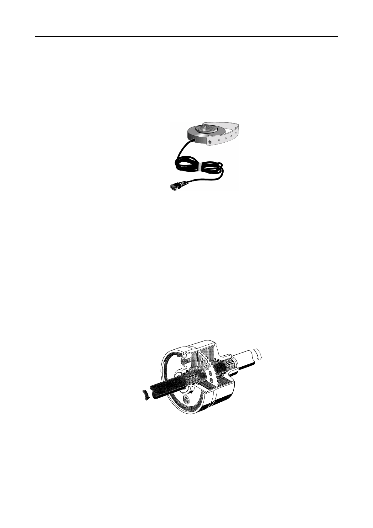
The measurement principle is the same for both methods of testing. The drive motor is
supported in a rotary fashion (motor housing not supported); without any additional support, the
drive shaft and the housing would counter rotate when under load, depending on the force
distribution. The additional support consists of a flexible beam, on which the housing rests. The
steel beam bends corresponding to the torque produced by the motor, which the beam resists.
The torque is zero at the beginning of the static test. With the dynamic test method, the torque is
just high enough to set the drive rollers with the vehicle wheel in motion with the brakes not
applied.
A strain gauge is mounted on the transverse beam which converts the brake force into a usable
electrical value.
For the IW4/IW7 WB/WBV (4WD)) brake tester the dynamic test method is used. This method
ensures the most accurate measurement. There is simply no alternative for 4 wheel drive brake
testing.
D1 0412BA1-GB04 1
Description IW4/IW7 WB/WBV
1.2.1 Vehicle with a Driven Axle
Drive the wheel axle to be tested onto the roller set. This will push both sensors rollers down
which measure the RPM of the wheels. Now both drive motors of the roller set will slowly
accelerated to nominal speed turning both vehicle wheels forward. When the drive motors have
reached nominal speed a comparison is made between the nominal drive roller speed and the
sensor roller speed in order to be able, at any time, to switch off the drive motors when a
slippage of 30% is exceeded. (This is to protect the drive motors against overload and the tires
against excessive wear.)
The READY indicator will light up, signaling that the test rig is ready to start the brake test.
During brake tests the vehicle is decelerated to a point, that at least one sensor roller exceeds
30% slippage and the drive motors are switched off.
1.2.2 4-Wheel Drive Vehicle
On non-permanent 4-wheel drive vehicles the brakes are tested with the 4-wheel drive switched
off, just like vehicles with only one drive axle.
Principle of 4 Wheel Drive
On 4-wheel drive vehicles the torque applied to the drive shaft is evenly distributed to all four
wheels, i.e. a quarter of the total torque will be applied to each wheel. The same applies for the
brake torques that arise when braking. When testing 4 wheel drive vehicles it must therefore be
ensured that no brake torque will be transferred from one vehicle wheel to the other. This is
accomplished if no torque is applied to the drive shaft of the differential during the brake test.
The following example will explain this in detail:
In order to simulate a defective brake, one brake is disabled. Now only one brake of the axle to
be tested is enabled. If the brake test is done on a standard test stand where the torque is not
eliminated from the drive shaft, the same force applies to the strain gauges of both drive motors,
i.e. the same brake torque will be indicated. This would lead to the false assumption that the
brakes are fully intact. If the test was conducted correctly, no brake torque would be indicated for
the wheel with the disabled brake and the actual brake torque applied to the other wheel would
appear.
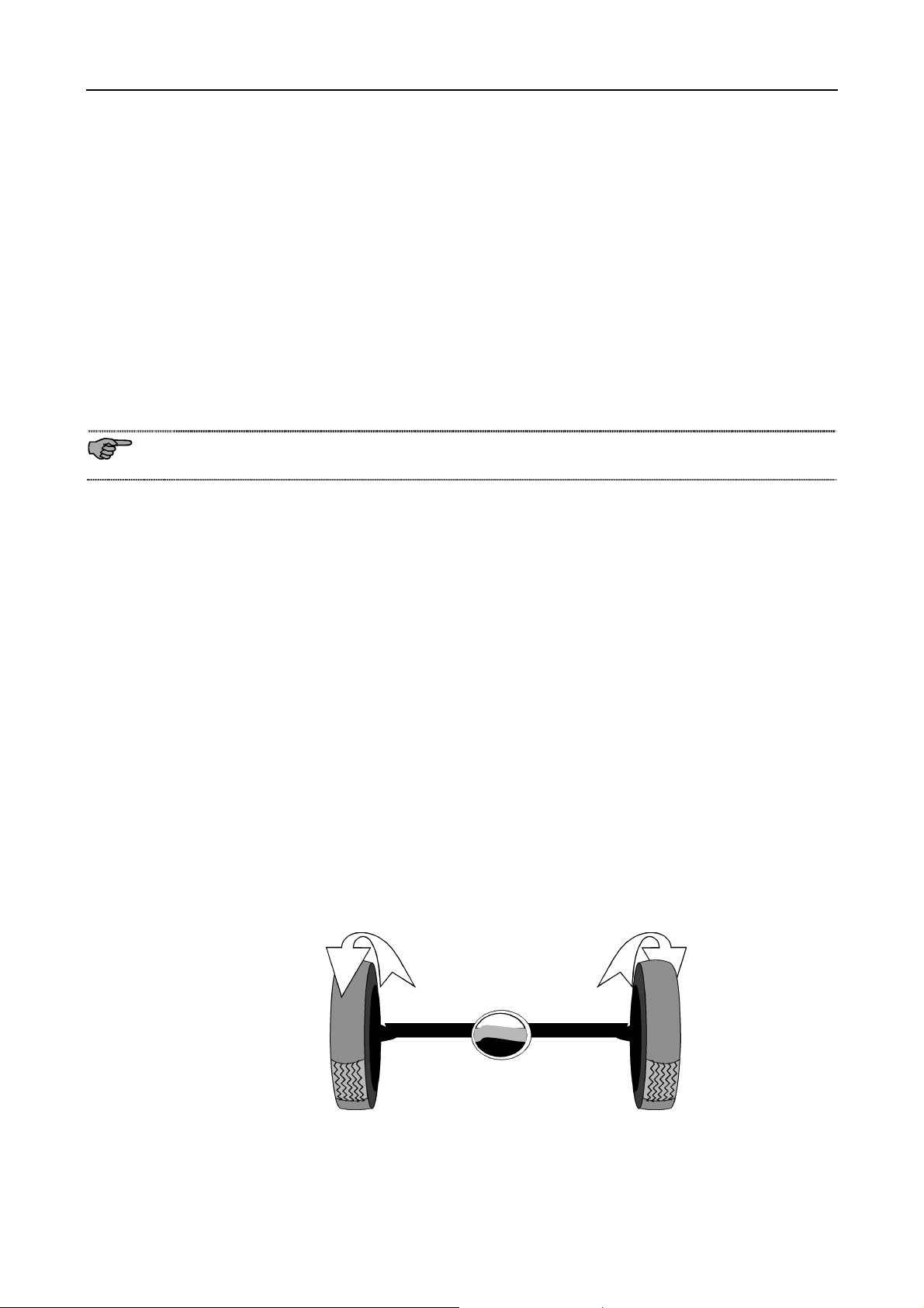
If both wheels of the axle to be tested are rotating forward during the brake test, the vehicle will
be lifted out of the test rig, as torque is transferred by the drive shaft to the wheels of the other
vehicle axle. To prevent this, the wheels counter rotate with the same RPM, one vehicle wheel is
driven in forward direction and the other wheel in reverse direction. This eliminates the torque
built-up in the differential against the drive shaft and transmission of torque to the other vehicle
axle.
2 D1 0412BA1-GB04
IW4/IW7 WB/WBV Description
As the brake characteristics depend on the rotating direction of the wheels (the brake linings and
brake drums are ground in forward direction), only the brake torque of the wheel rotating in
forward direction is measured. For this reason, the brake test has to be done separately for each
wheel.
In order to obtain a reliable comparision between the brake forces of both wheels of the same
axle, the same pedal force will have to be applied at the brake test of the left and right wheel. To
accomplish this, a pedal force meter can be connected to the vehicle's brake pedal.
It is also possible to measure the current pressure Pm of the hydraulic brake by means of a
pressure sensor.
Testing of various 4-wheel drive types
There are three different types of 4-wheel drives:
a) Disengageable drive shaft leading to the differential
b) Visco-clutch (VC) in the drive shaft leading to the differential
c) Rigid drive shaft between the differentials
a) Disengageable drive shaft leading to the differential
On vehicles equipped with non-permanent 4-wheel drive, the brakes are tested with the 4-wheel
drive switched off, just like vehicles with only one drive axle.
b) Visco-clutch (VC) in the drive shaft leading to the differential
There are two different Visco-clutch types. The soft Visco clutch has a higher torsibility
(viscosity) than the hard Visco clutch, therefore no torque is transferred to the other wheels
when the drive shaft rotation is low.
D1 0412BA1-GB04 3
Description IW4/IW7 WB/WBV
As described above, brake tests on 4-wheel drive vehicles are feasible if both wheels on the
same axle counter-rotate at the same speed. As, in practice, the circumference of the left and
right wheel is not exactly the same due to different tire tread depths and uneven tire pressure,
the RPM of the two drive motors is normally different. Therefore the drive motors must control
their speed in order to obtain the same RPM for both wheels.
Approximately the same speed of the roller set drive motors will be sufficient for a 4-wheel drive
vehicle having a soft VISCO clutch in the drive shaft as no brake torque is transferred by the
VISCO clutch when the drive shaft rotation is low. Therefore the speed control of the drive
motors alone will be sufficient in this case.
Contrary to the above, when testing the brakes of 4-wheel drive vehicle having a hard VISCO
clutch in the drive shaft both wheels on the same axle must rotate synchronously during the
brake test, as the clutch viscosity is so low that even the slowest rotation of the drive shaft will
transfer brake torque to the other wheels through the VISCO clutch.
c) Rigid drive shaft between the differentials
To perform a brake test on a 4-wheel drive vehicle having a rigid drive shaft, the wheel rotations
must be exactly controlled in such a way that no brake torque can be transferred by the drive
shaft.
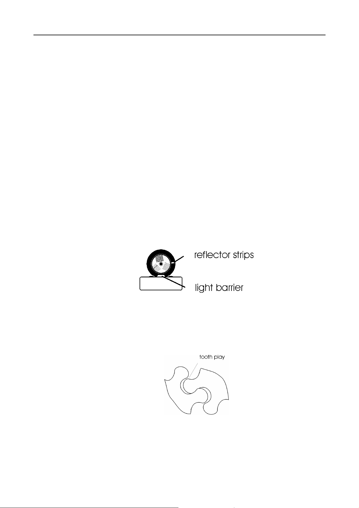
Controlling the synchroneous rotation of the wheels
In order to control synchronous rotation of the wheels, reflector strips are fastened to the sides
of the wheels which trigger a signal via two photo-electric cells, mounted on the side of the roller
set.
On vehicles equipped with a rigid drive shaft or with a hard Visco clutch the wheels cannot be
individually turned. If one vehicle wheel is turned forward in the roller set, the other wheel (on the
same axle) will be turning backwards in a synchronous manner. If one wheel is turned slowly in
forward or backward direction, one will note that the other wheel starts turning with a little delay.
This slight delay in following the other wheel to turn is caused by the gear play (backslash of
teeth) inside of the differential.
To perform a brake test on a 4-wheel drive vehicle having a rigid drive shaft, the wheel rotation
must be controlled in such a way that no brake torque can be transferred by the drive shaft. This
is achieved by staying within the gear play of the differential during the brake test. The
differential will be in a "balance" state.
4 D1 0412BA1-GB04
IW4/IW7 WB/WBV Description
To be able to effectively use this, the exact backlash of teeth is assessed in a learning mode:
Initially the left drive motor will be switched on to accelerate the left vehicle wheel to nominal
speed. As the right drive motor is switched off and thus running free, the left wheel is dragging
the right wheel along. The flanks of a tooth in the differential touch each other on one side. Now
the first limit position of gear play is measured by the reflector strips and the photo electric cells.
The procedure is now reversed, the left drive motor of the roller set is switched off and the right
vehicle wheel is accelerated to nominal speed. This time the left wheel is dragged along and in
the differential the flanks of teeth touch each other on the opposite side. The second limit
position of the gear play will now be measured. Out of the two measured limit positions the
center of gear play is calculated. This "center of gear play" is used to control the rotation of
wheels during the brake test.
During the brake test, both drive motors are accelerated to a speed where the "center of gear
play" is reached. One vehicle wheel will rotate forward, the other in opposite direction. As soon
as the nominal speed is reached by both wheels, and no brake torque is being transferred to the
drive shaft, brake testing may be started.
As with standard vehicles the drive motors will be switched off if excessive slip occurs.
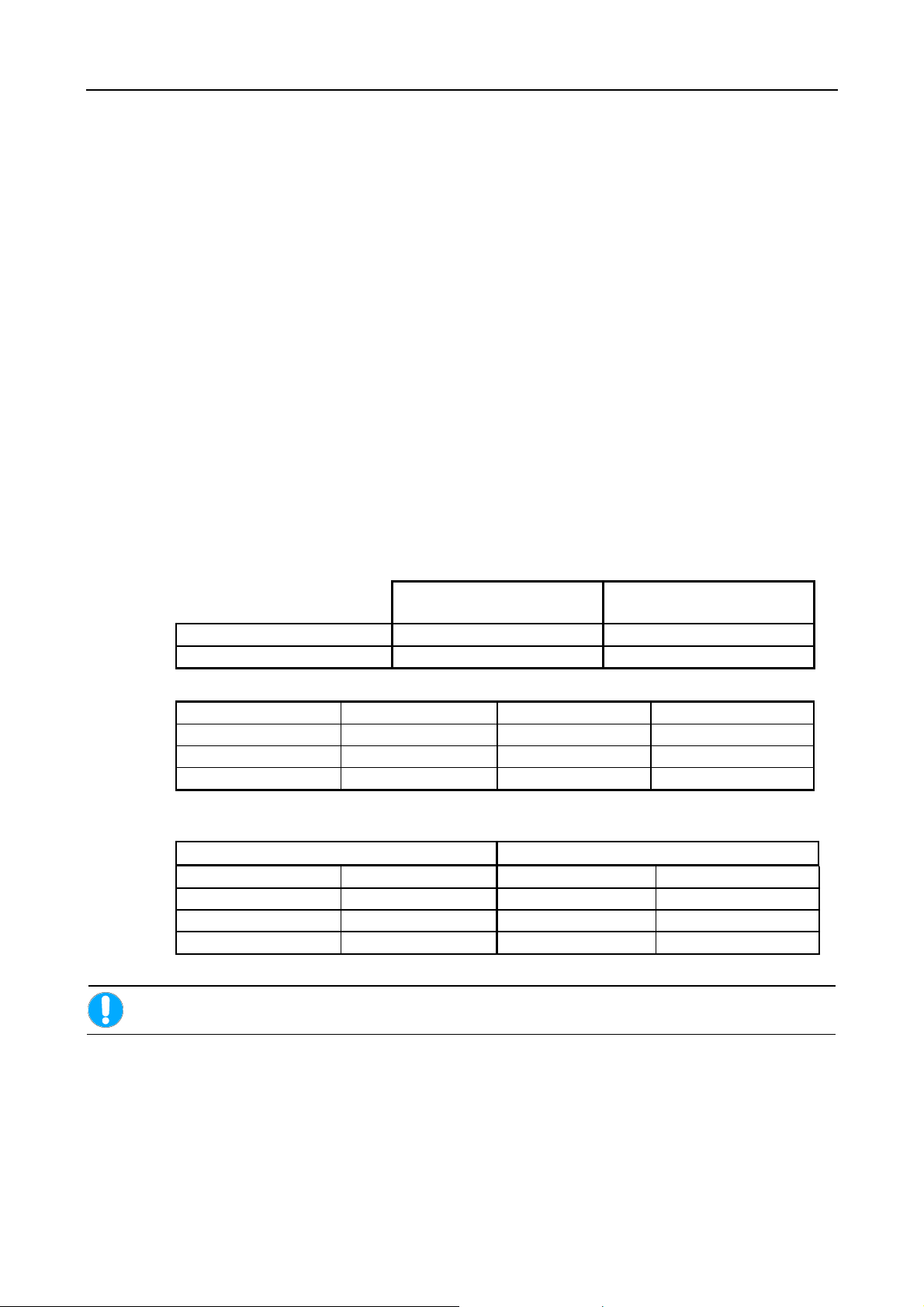
1.3 Technical Data
1.3.1 Electrical Data
IW7
Voltage supply 400 V, 3 Phases, 50 Hz 400 V, 3 Phases, 50 Hz
Special voltage 230 V, 3 Phases, 50 Hz 230 V, 3 Phases, 50 Hz
Motor drive capacity
IW7/1 2 x 7,5 kW IW4/1 2 x 7.5 kW
IW7/2 2 x 11 kW IW4/2 2 x 9 kW
IW7/3 2 x 11 kW
IW7/4 2 x 7,5 kW
Star delta starters for motors with IW7/1 E, IW7/2 E, IW4/1 E and IW4/2 E
Dahlander-control system for IW7/3 E and IW7/4 E
Main switch fuse Main switch fuse with special voltage
IW7/1 and IW7/4 50 A slow IW4 (4 wheel drive) 63 A slow
IW4/1 35 A slow IW7 (4 wheel drive) 100 A slow
IW4/2 50 A slow
IW7/2 and IW7/3 63 A slow
Only trained electricians or authorized service technicians are allowed to carry out work on
electrical parts of the brake tester. (Control box, roller set, etc.)
(4 wheel drive)
IW4
(4 wheel drive)
D1 0412BA1-GB04 5

Description IW4/IW7 WB/WBV
1.3.2 Mechanical Data
Axle load (Standard) roller
set, closed, self-supporting
Track ( e.g. Roller set No. 2) min.= 200 mm
max.=track min.+2200 mm
Roller diameter 265 mm 202 mm
Roller axle separation 475 mm 430 mm
Dimensions roller set (HxWxL) 700x1142x1427 mm (HxWxL) 500x1043x1225mm
Test speed
IW7/1 3 km/h IW4/1 2.3 km/h
IW7/2 3 km/h IW4/2 2.3 km/h
IW7/3 3 km/h and 6 km/h
IW7/4 3 km/h and 6 km/h
Roller friction coeffic ients
Steel IW7
(4 wd)
Dry ca. 0.9 ca. 0.9 dry ca. 0.9 ca. 0.9
Wet ca. 0.9 ca. 0.7 wet ca. 0.9 ca. 0.9
IW4
(4 wd)
IW7
(4 wd)
max. 18 t max. 13 t
max.=track min.+2200 mm
Plastic IW7
(4 wd)
IW4
(4 wd)
min.= 200 mm
IW4
(4 wd)
Display range depending on model
IW7 (4 wd) IW4 (4 wd)
small measuring range 2 x 0-6 kN (optional 2 x 0-8 kN) 2 x 0-7,5 kN
large measuring range 2 x 0-30 kN
(optional 2 x 0-40 kN)
Diameter Analog display 350 mm 350 mm
Display accuracy > 2%
Measuring accuracy > 1%
Operating temperature -10°C to +40°C
Double pressure pneumatic gauge
Pressure gauge dial diameter 200 mm
2 x 0-30 kN
6 D1 0412BA1-GB04

IW4/IW7 WB/WBV Description
1.3.3 Electronic
Processor PCB with operating system
EEPROM for variable system configuration
6 Slots for system expansion
Serial interface RS 232
Connection for LCD-Display
Subject to technical alterations without notice!
Only trained electricians or authorized service technicians are allowed to carry out work on
electrical parts of the brake tester. (Control box, roller set, etc.)
1.4 Standard Equipment IW4/IW7 WB/WBV (4WD)
IW4 (4WD): Roller set no.1 or no.2
IW7 (4WD): Roller set no.2
Single wheel mode
Delayed automatic switch on
Automatic switch-off after exiting the roller set
Automatic slip switch-off including pointer stop and automatic re-start
Electronic strain gauge
Lockable main switch
RS 232 Interface
Optional:
Weighing system; static (2 pressure cells) or dynamic (4 pressure cells)
Standard equipment subject to change without notice.
Standard equipment of the c urrent price list apply.
In addition to the standard versions, Maschinenbau Haldenwang (MAHA) offers various expansion possibilities which
are listed in the current pric e l i st.
1.5 Noise Emission
The noise emission value created when the tester is in operation is less than 70dB(A) in the
work area of the operational personnel.
D1 0412BA1-GB04 7

Description IW4/IW7 WB/WBV
1.6 Equipment IW7 MB Version
! The roller brake testers equippped with the Mercedes-Benz-Program differ in several aspects
from the standard version:
! Sticker indicating MB-recognition and month and year of production
! Optical acknowledgement of the slip shut-off via 2 lamps below the display instruments
! Manual- and automatic operation
! Remote control
! Key switch / Emergency-Off switch on the front side of the display panel (optionally available
for inspection pit)
! Counter for hours of operation
! Calibration possibilities using push button in control cabinet while drive motors running
! Possible to install roller set using MAHA-adapter set in MB-standard pit
! Running rollers made of grooved steel with sanding or synthetic coating
! Additional malfunction-release button with integrated malfunction lamp
8 D1 0412BA1-GB04
IW4/IW7 WB/WBV Safety
2 Safety
2.1 Introduction
Before commissioning the machinery please read the operating instructions carefully and
thoroughly and comply with the instructions. The instruction manual should always be
conveniently stored to be readily accessible at all times.
Injury to persons incurred due to non-compliance with these operating instructions is not covered
by the product liability laws.
MAHA will not accept and is not liable for any claims for damage to the test stand and/or vehicle
or service costs incurred due to non-compliance with these operating instructions.
Warning means that instructions that are not complied with or incompletely complied
with can endanger persons.
Attention means that instructions that are not complied with or incompletely complied
with can lead to equipment damage.
Notes provide additional information.
Safety information is provided to warn about dangerous situations and help prevent damage to
equipment and injury to persons. For your own safety it is imperative that all safety regulations
included in these instruction be carefully observed.
Carefully observe all national and international safety and health regulations. Every user is
responsible for observing all regulations which apply to his workplace and is obliged to integrate
any new regulations that may be initiated.
D1 0412BA1-GB04 9
 Loading...