

Page 1
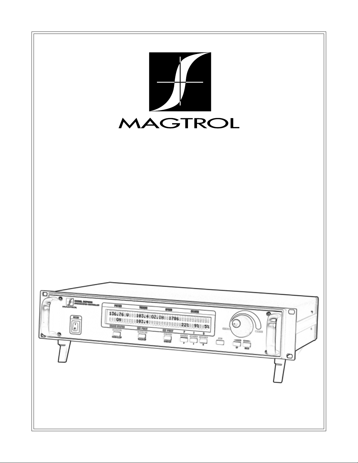
Model DSP6000Model DSP6000
Model DSP6000
Model DSP6000Model DSP6000
High Speed PHigh Speed P
High Speed P
High Speed PHigh Speed P
Dynamometer ControllerDynamometer Controller
Dynamometer Controller
Dynamometer ControllerDynamometer Controller
rogrammablerogrammable
rogrammable
rogrammablerogrammable
UserUser
User
UserUser
’s Manual’s Manual
’s Manual
’s Manual’s Manual
Page 2

MAGTROL, INC.MAGTROL, INC.
MAGTROL, INC.
MAGTROL, INC.MAGTROL, INC.
Sales and TSales and T
Sales and T
Sales and TSales and T
Buffalo, New York 14224 USA
Tel: (716) 668-5555 or 1-800-828-7844
wwww
ww
wwww
Hysteresis Brakes and Clutches
While every precaution has been exercised
in the compilation of this document,
Magtrol, Inc. assumes no responsibility
for errors or omissions. Additionally, no
liability is assumed for any damages that
may result from the use of the information
contained within this publication.
echnical Assistanceechnical Assistance
echnical Assistance
echnical Assistanceechnical Assistance
70 Gardenville Parkway
Fax: (716) 668-8705
w.w.
mm
w.
w.w.
Manufacturers of:
Motor Test Equipment
agtragtr
m
agtr
mm
agtragtr
oo
l.cl.c
oo
o
l.c
o
oo
l.cl.c
oo
!
mm
m
mm
74M041 062200
®
LabVIEW
National Instruments Corporation.
RadioShack
the RadioShack Corporation.
is a registered trademark of
®
is a registered trademark of
Page 3

Safety NotesSafety Notes
Safety Notes
Safety NotesSafety Notes
1. Make sure that all Magtrol dynamometers and electronic products are earthgrounded, to ensure personal safety and proper operation.
2. Check line voltage before operating the DSP6000.
3. Make sure that dynamometers and motors under test are equipped with
appropriate safety guards.
iii
Page 4

This page intentionally left blank.
iv
Page 5

TT
able of Contentsable of Contents
T
able of Contents
TT
able of Contentsable of Contents
SALES AND TECHNICAL ASSISTANCE .............................................................................................. ii
SAFETY NOTES..................................................................................................................................... iii
1 - INTRODUCTION ................................................................................................................................ 1
About This Manual ............................................................................................................................................. 1
Shipping .............................................................................................................................................................. 1
UNPACKING YOUR DSP6000 ............................................................................................................................................ 1
About the Model DSP6000 Dynamometer Controller ....................................................................................... 1
FEATURES ......................................................................................................................................................................... 1
SPECIFICATIONS ................................................................................................................................................................. 2
Front Panel .......................................................................................................................................................... 3
Figure 1. Front Panel .................................................................................................................................... 3
ENABLING SECONDARY FUNCTIONS ..................................................................................................................................... 3
FRONT PANEL CONTROLS AND BUTTONS ............................................................................................................................. 4
Vacuum Fluorescent Display (VFD) .................................................................................................................. 5
STATUS DISPLAY MESSAGES ..............................................................................................................................................5
DISPLAYING DESIRED INFORMATION .................................................................................................................................... 5
Rear Panel ........................................................................................................................................................... 6
Figure 2. Rear Panel ..................................................................................................................................... 6
Figure 3. Brake Connector ............................................................................................................................ 6
Figure 4. Accessory Torque/Speed Output.................................................................................................... 6
Figure 5. Dynamometer Connector ............................................................................................................... 6
REAR PANEL FUNCTIONS ....................................................................................................................................................7
2 - ABOUT THE PID LOOP..................................................................................................................... 8
P (Proportional Gain) ......................................................................................................................................... 8
I (Integral) .......................................................................................................................................................... 8
D (Derivative) .................................................................................................................................................... 8
Figure 6. PID Loop ....................................................................................................................................... 8
Setting The Correct PID'S For Your Motor ........................................................................................................ 8
3 - INSTALLATION................................................................................................................................ 10
Setting Unit for Line Voltage ........................................................................................................................... 10
Figure 7. Cover for Voltage Selector, Fuses ...............................................................................................10
Checking Your DSP6000 .................................................................................................................................. 10
4 - THE DSP6000 AS A STAND-ALONE UNIT (LOCAL CONTROL) ................................................. 12
Setting Desired Operating Parameters .............................................................................................................. 12
SET DISPLAY TO DESIRED POWER UNITS (WATTS OR HP) .................................................................................................. 12
SET DISPLAY TO DESIRED TORQUE UNITS .........................................................................................................................12
SET UP DISPLAY FOR DYNAMOMETER ............................................................................................................................... 12
SET UP COMMUNICATIONS WITH PC .................................................................................................................................12
SET UP AUXILIARY INPUT ................................................................................................................................................ 12
SET TORQUE CONTROL ....................................................................................................................................................12
SET SPEED CONTROL ....................................................................................................................................................... 13
SET OPEN LOOP CONTROL ...............................................................................................................................................13
SET UP I/O PARAMETERS ................................................................................................................................................ 13
Setting Dynamometer Load .............................................................................................................................. 14
Using Internal Memory..................................................................................................................................... 14
STORING DATA POINTS ....................................................................................................................................................14
RECALLING DATA POINTS ................................................................................................................................................ 14
v
Page 6

EXITING THE MEMORY MODE .......................................................................................................................................... 14
CLEARING THE MEMORY .................................................................................................................................................. 14
5 - THE DSP6000 WITH A PC (REMOTE CONTROL) ......................................................................... 15
About the GPIB Interface ................................................................................................................................. 15
Figure 8. GPIB (IEEE-488) Interface .........................................................................................................15
I
NSTALLING THE GPIB (IEEE-488) CONNECTOR CABLE ................................................................................................... 15
CHANGING THE GPIB PRIMARY ADDRESS .........................................................................................................................15
Checking the DSP6000-To-PC Connection...................................................................................................... 16
Programming .................................................................................................................................................... 16
CODES FOR CR - LF ....................................................................................................................................................... 16
DSP6000 Command Set ................................................................................................................................... 16
COMMAND SET FOR DSP6000.........................................................................................................................................17
Acquiring Speed-Torque Data .......................................................................................................................... 20
Selecting the Baud Rate for the RS-232 Interface ............................................................................................ 20
Figure 9. Connector Pin-Out ...................................................................................................................... 20
6 - CALIBRATION ................................................................................................................................. 21
Closed-Box Calibration .................................................................................................................................... 21
Calibration Schedule ......................................................................................................................................... 21
Basic Calibration Process ................................................................................................................................. 21
INITIAL CALIBRATION PROCEDURE .................................................................................................................................... 21
TORQUE OFFSET AND GAIN .............................................................................................................................................. 21
ACCESSORY TORQUE OFFSET AND GAIN ............................................................................................................................22
AUXILIARY INPUT OFFSET AND GAIN ................................................................................................................................22
ALTERNATE CALIBRATION PROCEDURE.............................................................................................................................. 22
Figure 10. Alternative Calibration ................................................................................................................ 23
7 - TROUBLESHOOTING ..................................................................................................................... 24
APPENDIX A: LABVIEW® PROGRAMMING EXAMPLES................................................................. 25
Simple Read ...................................................................................................................................................... 25
Torque Stabilized .............................................................................................................................................. 26
Speed Stabilized ................................................................................................................................................ 27
APPENDIX B: INERTIA CORRECTION .............................................................................................. 28
Inertial Effect on Motor Test Data.................................................................................................................... 28
Procedure for Inertia Correction ....................................................................................................................... 28
KEY CONDITIONS ............................................................................................................................................................ 28
APPENDIX C: FRONT PANEL/DISPLAY MENU FLOW CHARTS..................................................... 29
Dyno Setup Menu ............................................................................................................................................. 29
Com Setup Menu .............................................................................................................................................. 30
Aux Setup Menu ............................................................................................................................................... 31
Power Units Menu ............................................................................................................................................ 31
Torque Units Menu ........................................................................................................................................... 32
APPENDIX D: SCHEMATICS .............................................................................................................. 33
Encoder/Switch Board ...................................................................................................................................... 33
Power Supply .................................................................................................................................................... 33
DSP & Memory ................................................................................................................................................ 34
Analog I/O ........................................................................................................................................................ 35
GLOSSARY OF ABBREVIATIONS AND TERMS................................................................................ 36
MAGTROL LIMITED WARRANTY ....................................................................................................... 37
vi
Page 7

1 - Introduction1 - Introduction
1 - Introduction
1 - Introduction1 - Introduction
ABOUT THIS MANUAL
This manual contains information about the DSP6000
Dynamometer Controller and procedures for optimal
use. To obtain the best results from your unit, please
follow the procedures for operation.
SHIPPING
Your DSP6000 was packaged carefully for shipping.
Please notify your carrier and Magtrol Customer Service
if you believe your unit was damaged in shipping.
UNPACKING YOUR DSP6000
1. Save all shipping cartons and packaging material
until you inspect the DSP6000.
2. Inspect the DSP6000 for any evidence of damage
in shipping.
3. Make sure the carton contains the following:
• DSP6000 Dynamometer Controller
• Line cord
• User's Manual for the DSP6000
• Calibration certificate
ABOUT THE MODEL DSP6000 DYNAMOMETER CONTROLLER
Magtrol's Model DSP6000 Dynamometer Controller
provides superior motor testing capabilities by using
state-of-the-art digital signal processing technology.
The DSP6000 both controls the dynamometer and
provides digital readouts on the front panel. The
DSP6000 is designed to work with all Magtrol load cell
dynamometers, including the following dynamometer
models:
001-DH 015-DH 008-DH 517-DE
601-DH007-DH508-DH518-DE
004-DH 507-DH 018-DH 001-DTH
005-DH017-DH518-DH002-DTH
505-DH 517-DH 528-DH 003-DTH
FEATURES
Fast, full curve data acquisition
Free-run to locked rotor in seconds.
High-speed data acquisition
120 torque and speed points per second via IEEE
(GPIB) bus.
Speed and torque operating modes
Each mode provides independent PID settings for
improved dynamometer control.
Programmable digital PID values
Controlled and stored either with Magtrol M-Test
software or manually.
Single point or programmed load control
Single or multi-point torque and speed stabilized testing
using Magtrol M-Test software.
Two standard computer interfaces
RS-232 and IEEE-488.
Additional analog input
Accepts any ± 5 VDC transducer.
Vacuum fluorescent display
Displays torque, speed, power, auxiliary input and PID
values.
Many torque measurement options
Includes English, metric, and SI torque readings as
standard.
Closed box calibration of torque and auxiliary input
Eliminates need to open box for adjustments.
The DSP6000 is designed to work with any personal
computer using an IEEE-488 or an RS-232 interface,
or as a stand-alone unit. In a computer-controlled
environment, the DSP6000 provides the following
motor testing capabilities:
• Proportional (P), plus Integral (I), plus
Derivative (D) closed loop control (PID loop).
• Torque (Q) and Speed (N) data acquisition at a
rate of up to 120 readings per second.
• Automatic progressive loading in either
decreasing or increasing speed mode.
• Ability to remove the Effects of Inertia from
dynamically obtained data. (See Appendix B)
• Complete curve capability for most motor
types, including single/poly phase induction,
AC/DC series, PMDC, brushless DC, air and
internal combustion (if suitably coupled).
1
Page 8
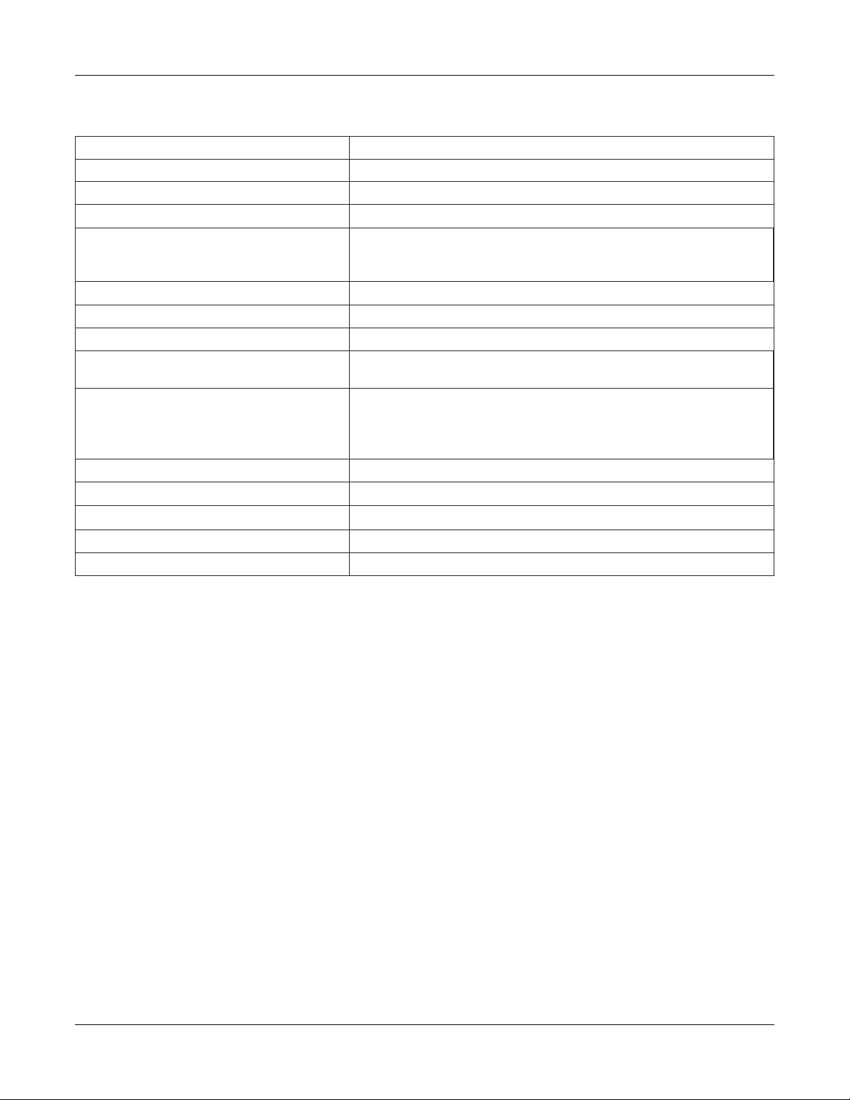
SPECIFICATIONS
Magtrol Model DSP6000 Dynamometer ControllerChapter 1 - Introduction
snoisnemiD
thgieW
erutarepmeTgnitarepO
ytidimuHevitaleR
ycaruccA
tneiciffeoCerutarepmeT
tupnI.xuA
tuOlrtC
tuptuOdeepS/euqroTyrosseccA
)mm02x5(sesuF
stnemeriuqeRrewoP
stnemeriuqeRegatloV
deepSmumixaM
euqroTmumixaM
egatloVecnailpmoCmumixaM
bl5.61
C°52otC°81
%08<
:deepS
:euqroT
:xuA
CDV5±
CDV3-0
:euqroT
:deepS
:ekarB
:)V021(rewoP
:)V042(rewoP
AV57
MPR999,99
stinu0002
CDV54
H"5.3xD"8.31xW"91
MPR000,001otMPR01morfgnidaerfo%10.0
)V2±(egnarfo%2.0
)V5±(egnarfo%1.0
C°/egnarfo%100.0
CDV2±
elcycytud%05,ver/seslupLTT06
A52.1
A1
Am008
Am513
zH05/06V042/021
ASC/LU
CEI
ASC/LU
CEI
052V
V052
V052
V052
BS
T
BS
T
2
Page 9
Magtrol Model DSP6000 Dynamometer Controller Chapter 1 - Introduction
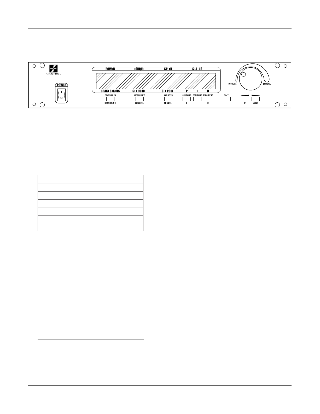
FRONT PANEL
Figure 1. Front Panel
MODEL DSP6000
DYNAMOMETER CONTROLLER
The front panel provides a power switch, eight control
buttons, a Decrease/Increase Dial, and Vacuum
Fluorescent Display (VFD). The front panel controls
and buttons, from left to right, are:
• Power switch
• Six double-function control buttons:
noitcnuFyramirPnoitcnuFyradnoceS
FFO/NOEKARBSTINUREWOP
TESEUQROTSTINUEUQROT
TESDEEPSDEEPSXAM
PPUTESXUA
IPUTESMOC
DPUTESONYD
• Three single-function control buttons:
• SHIFT (to enable secondary functions printed
in blue above control buttons)
!
• Up/Left arrow
(scroll up, increase
magnitude)
"
• Down/Right arrow
(scroll down,
decrease magnitude)
• Decrease/Increase Dial
ENABLING SECONDARY FUNCTIONS
To enable the secondary function of the double-function
control buttons:
1. Press the blue SHIFT button and release it. (The
word SHIFT appears in the display.)
2. Press a control button to enable the function shown
in blue letters above the control button:
POWER UNITS, TORQUE UNITS, AUX SETUP,
COM SETUP or DYNO SETUP.
3. Press the SHIFT button again to exit the secondary
function.
NOTE: Refer to the table, “Front Panel
Controls and Buttons” later in
this chapter for further
explanation of button features
and use.
3
Page 10
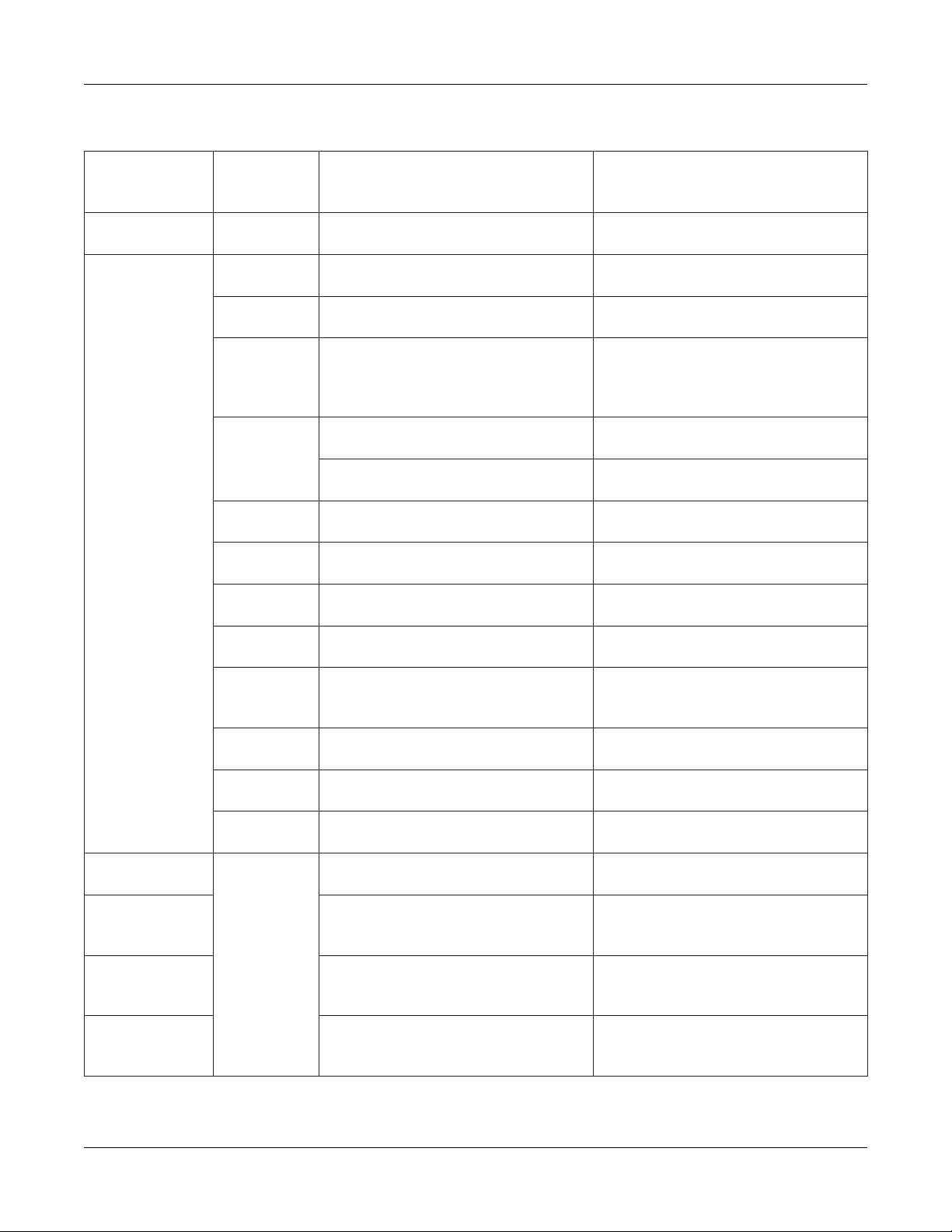
FRONT PANEL CONTROLS AND BUTTONS
Magtrol Model DSP6000 Dynamometer ControllerChapter 1 - Introduction
elgniS/slortnoC
noitcnuF
snottuB
REWOP
TES
-elbuoD
noitcnuF
snottuB
REWOP
STINU
EKARB
FFO/NO
EUQROT
STINU
EUQROT
DEEPSXAM
TESDEEPS.nottubsihtsserP.gnidaoldeepsroftnioptesswohS
PUTESXUA
.nottubsiht
.nottubsiht
.peeb
.nottubsiht
.nottubsiht
esUoTnoitcnuF
otOsserPNOrewopnrutotIsserP
.FFOrewopnrut
sserpneht;esaelerdnaTFIHSsserP
.nottubsihtsserP.NOroFFOekarbselggoT
sserpneht;esaelerdnaTFIHSsserP
.nottubsihtsserPgnidaoleuqrotroftnioptesswohS
dnoceslitnunottubsihtdlohdnasserP
sserpneht;esaelerdnaTFIHSsserP
sserpneht;esaelerdnaTFIHSsserP
.FFOroNOrewopsnruT
.sttaWotyalpsidrewopsteS
sserP.erusaemfotinuderisedsteS
PU ! NWODro " eesotnottub
elbaneotTFIHSsserP.snoitpo
.noitpo
.gnidaolpoolneporoftnioptesswohS
.rellortnocehtfoegnardeepsehtsteS
.FFOroNOyalpsidyrailixuasnruT
.ecivedtupniyrailixuafognilacssteS
P.nottubsihtsserP.niaglanoitroporpstsujdA
I.nottubsihtsserP.largetnistsujdA
ONYD
PUTES
D.nottubsihtsserP.evitaviredstsujdA
TFIHS
TFEL/PU ! .sserP
THGIR/NWOD " .sserP
ESAERCED
ESAERCNI/
LAID
PUTESMOC
.nottubsiht
.nottubsiht
.nottublortnocderisedsserp
sserpneht;esaelerdnaTFIHSsserP
.tsartnocyalpsid
sserpneht;esaelerdnaTFIHSsserP
.redocne
neht,esaelerdnanottubsihtsserP
.nottublortnocevoba
.)deeps.xamroeuqrot
.)deeps.xamroeuqrot
.esiwkcolcretnuocroesiwkcolcnruT
.detcelesretemarap
ehtsesaercnirosesaerceD
dnasserddayramirpBIPGstsujdA
stsujdaoslA.etarduab232-SR
deepsdnastinueuqrottupnistceleS
eulbninettirwnoitcnufehtsetautcA
nehwegnahcfoedutingamsesaercnI
,deeps(eulavlaciremunagnitsujda
nehwegnahcfoedutingamsesaerceD
,deeps(eulavlaciremunagnitsujda
4
Page 11
Magtrol Model DSP6000 Dynamometer Controller
Chapter 1 - Introduction
VACUUM FLUORESCENT DISPLAY (VFD)
The VFD provides information about the control
functions, the motor under test, and an auxiliary input
device (if connected). The displays, from left to right,
are:
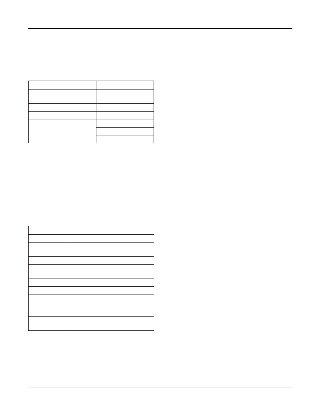
woRpoTwoRmottoB
REWOP
)sttaWropHnidesserpxe(
EUQROT)EUQROT(TNIOPTES
DEEPS)DEEPS(TNIOPTES
SUTATSroTUPNIXUA
YALPSID
P
I
D
SUTATSEKARB
)FFOroNO(
The DSP6000 is shipped with the Contrast setting at
zero (lowest) in order to prolong display life. If it is
necessary to increase the contrast for improved
readability, use the lowest possible setting to achieve
that result. Using a setting higher than necessary may
cause display segments to burn-in over a period of time,
resulting in uneven illumination from segment to
segment.
STATUS DISPLAY MESSAGES
egasseMgninaeM
TFIHS.desserpsawnotubtfihS
XUA
DEEPSXAM
RORREO/I
STINU
QCATSAF
ETOMER
NWODPMAR
PUPMAR
.delbane
.retupmoc
dnadehcattasitinuyrailixuA
.MPRrotommumixaM
morftnessawdnammoctcerrocnI
.tnemerusaemfotinueuqroT
.edomdeeps-hgihniatadgniriuqcA
.delbaneCPaivlortnocetomeR
ybdeepsrotomesaerceD
.rotomnodaolgnisaercni
ybdeepsrotomesaercnI
.rotomnodaolgnisaerced
DISPLAYING DESIRED INFORMATION
Local control:
1. Press SHIFT and release; then press POWER
UNITS to see UNITS displayed.
!
2. Press UP
or DOWN
available choices.
3. Press SHIFT to exit.
4. Press SHIFT and release; then press TORQUE
UNITS to see UNITS displayed.
!
5. Press UP
or DOWN
options for units.
6. Press SHIFT to exit.
7. Press RECALL to view memory contents; last in =
first out.
8. Press SHIFT to exit.
Remote control:
Refer to “DSP6000 Command Set” in Chapter 4 - The
DSP6000 with a PC for a list of commands recognized
by the DSP6000.
Auxiliary Input:
1. Press SHIFT and release; then press AUX SETUP.
2. Rotate Decrease/Increase Dial to select scale.
3. Press SHIFT to exit.
"
to scroll through
"
to scroll through
5
Page 12
Magtrol Model DSP6000 Dynamometer ControllerChapter 1 - Introduction
1
2
3
4
5
6
7
8
9
10
11
12
13
14
COMMON
D.P.
TACH. SIGNAL
N/C
D.P.
TORQUE COMMON
TORQUE SIGNAL
N/C
N/C
+
-
+
-
TACH. +5.0 VDC
ISOLATED
22 VDC
ISOLATED
22 VDC
CONNECTOR SHELL
& CABLE SHIELD
REAR PANEL
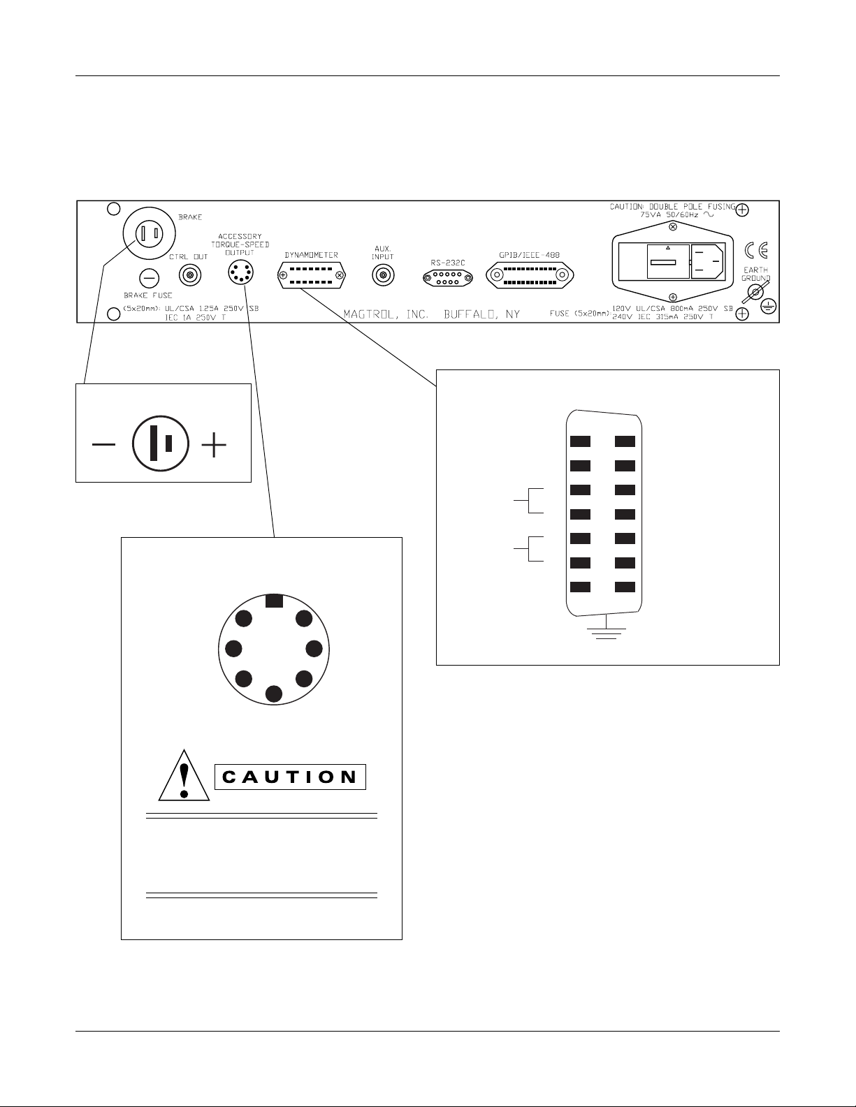
The rear panel provides connectors and receptacles for connecting to appropriate equipment.
Figure 2. Rear Panel
Figure 3. Brake Connector
Figure 4. Accessory Torque/Speed Output
TACH.
COMMON
TACH.
SIGNAL
TORQUE
COMMON
67
D.P.
13
45
2
N/C
TORQUE
OUTPUT
Figure 5. Dynamometer Connector
D.P.
6
For use with Magtrol Readouts
only. Connecting another device
to this output may cause
equipment failure.
Page 13
Magtrol Model DSP6000 Dynamometer Controller Chapter 1 - Introduction
g
g
g
g
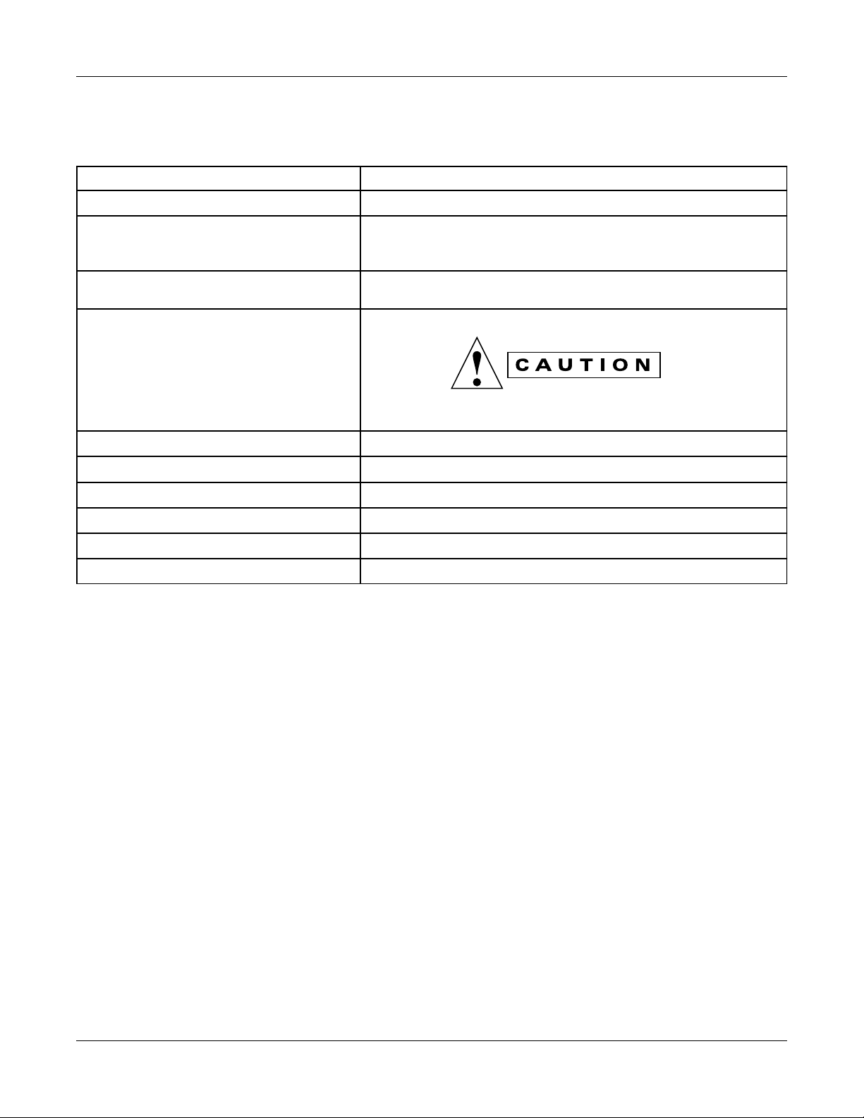
REAR PANEL FUNCTIONS
The rear panel, from left to right, provides the following functions:
Label Function
BRAKE Connect dynamometer brake cable here
Contains brake fuse (5 x 20mm)
BRAKE FUSE
CTRL OUT
ACCESSORY TORQUE-SPEED OUTPUT
UL/CSA 1.25A 250V SB
IEC 1A 250V T
Connect to Model 5241 Power Amplifier when usin
Dynamometer
Connect accessory output cable here (optional).
HD-825
For use with Ma
this output may cause equipment failure.
DYNAMOMETER Connect dynamometer si
AUX INPUT Connect auxiliary instrument cable here
RS-232C Use this socket for RS-232 connector cable
GPIB/IEEE-488 Use this socket for GPIB cable (meets IEEE-488 specifications)
POWER Attach power cord here
EARTH GROUND Attach earth
trol Readouts only. Connecting another device to
nal cable here
round here
7
Page 14
2 - About the PID L2 - About the PID L
2 - About the PID L
2 - About the PID L2 - About the PID L
oopoop
oop
oopoop
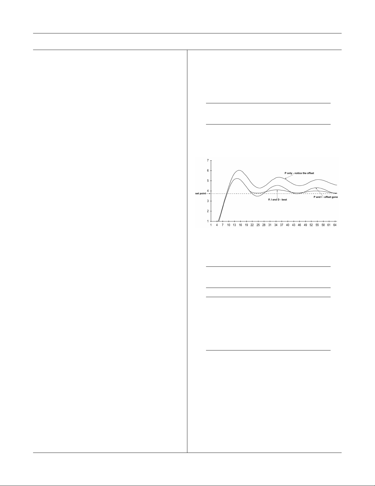
The DSP6000 has PID adjustment capability for both
the speed and torque modes to provide you with the
best system response. The PID Loop comprises the
following three variables:
P = Proportional Gain
I = Integral
D = Derivative
The setpoint is the desired load or speed. Error is the
difference between the setpoint and the actual
measurement.
P (PROPORTIONAL GAIN)
With proportional gain, the controller output is
proportional to the error or to a change in measurement.
Deviation from the setpoint is usually present.
Increasing proportional gain will make the PID loop
unstable. Increasing integral value eliminates this
instability. For best loop control, set the proportional
gain as high as possible without causing the loop to
become unstable.
I (INTEGRAL)
With integral, the controller output is proportional to
the amount of time the error is present. Increasing the
integral value eliminates the offset from the setpoint. If
the response becomes oscillatory, increase the derivative
value.
D (DERIVATIVE)
With derivative, the controller output is proportional to
the rate of change of the measurement or error.
Derivative can compensate for a changing measurement.
Derivative takes action to inhibit more rapid changes
of the measurement than proportional gain.
When a setpoint change occurs, the derivative causes
the controller gain to go the "wrong" way when the
measurement gets close to the setpoint. Derivative can
be used to control overshoot. If derivative is used, higher
gain and integral values are usually necessary.
Magtrol offers a comprehensive motor-test program
which would satisfy most of your needs. Call Magtrol
Sales at 1-800-828-7844 or 1-716-668-5555 to request
your custom software.
NOTE: To set PID values, see Chapter 3
- Installation.
Figure 6. PID Loop
SETTING THE CORRECT PID'S FOR YOUR MOTOR
NOTE: Each type of motor may have it's
own optimum PID setting.
NOTE: The PID settings are scaled to the
maximum speed setting;
therefore the maximum speed
setting should be adjusted to just
higher than the free-run speed of
the motor being tested.
When testing a new motor where the optimal PID's are
unknown:
1. Begin with the Proportional Gain (P) and the
Integral (I) both set to a low value and the Derivative
(D) set to zero. This will allow the best opportunity
for finding the optimum in the lowest amount of
steps.
2. Using the DSP6000 in the speed mode: Set the
speed target at approximately 90% of the free-run
speed.
8
Page 15

Magtrol Model DSP6000 Dynamometer Controller
Chapter 2 - About the PID Loop
3. Turn the brake to the ON position and observe how
the actual speed moves toward the target speed.
4. If the speed moves slowly or not at all, increase the
P until the target speed is achieved.
5. Turn the brake OFF.
6. Turn the brake ON and note how fast the free-run
speed changes to the target speed.
7. If the speed conversion does not happen quickly,
increase the I value.
8. Repeat steps 4-7 until the motor moves from the
free-run to the target speed as quickly as possible
without excessive overshoot.
Example:
Motor type: AC
Free-Run speed: 1750
1. Set maximum speed to 1800
2. Set P = 5 I =5 D = 0
3. Set target speed to 1600
4. Turn brake ON—no response
5. Move P value to 10—still slow, not reaching 1600
The larger the I value the faster the DSP6000 will move
to the target number, but an I value too large will cause
instability (oscillation). Once the optimum values are
found, these steps should be repeated at different
percentages of speed to ensure that they are the best
combination for the entire speed range.
NOTE: The PID values for a speed
stabilized test and a ramp test
will vary. Therefore, PID
adjustments may be needed when
changing from a stabilized test to
ramp testing with the same
motor.
The D value has little or no effect on this type of testing,
therefore the D value can remain at zero.
Note: Increasing the P more will not
increase the operating
characteristics without first
increasing the I value.
6. Turn brake OFF
7. Move I value to 10
8. Turn brake ON—Reaching 1600 very slowly
9. With the brake OFF, adjust the P to 15
10. Turn the brake ON—never reaching 1600
11. Turn the brake OFF. Decrease the P to 10 and
increase the I to 15
12. Turn the brake ON—reaches 1600 Faster
13. Turn the brake OFF. Increase I to 20
14. Turn the brake ON—reaches 1600 Faster
15. Turn the brake OFF. Increase I to 25
16. Turn the brake ON—reaches 1600 Faster
17. Turn the brake OFF. Repeat
9
Page 16

3 - Installation3 - Installation
3 - Installation
3 - Installation3 - Installation
Before installing your DSP6000, you should become
familiar with the front and rear panels, as outlined in
Chapter 1-Introduction.
Make sure the DSP6000 is earth
grounded before starting!
SETTING UNIT FOR LINE VOLTAGE
The DSP6000 will operate with either of the following
power sources:
• 120V 50/60 Hz
• 240V 50/60 Hz
1. Find the line cord receptacle on rear panel. The
line cord is a detachable NEMA Standard 3 wire.
2. Make sure the selector matches the power source
(numbers should match the line voltage).
If not:
• Locate the power entry module.
• Remove the line cord.
• Insert a screwdriver into the slot and open the
cover.
• Slide the voltage selector so the desired line
voltage appears in the window.
• Install the appropriate fuses for that voltage.
CHECKING YOUR DSP6000
Do not overload or stall the motor.
Prolonged overload can cause the motor
to overheat.
NOTE: To ensure that the DSP6000 is
operational, a Magtrol
Dynamometer with a test motor
installed must be connected to
the DSP6000. It is not required
that the DSP6000 be connected
to a computer.
1. Connect the DSP6000 to the dynamometer using
the following cables:
• 14-pin signal cable
• 2-pin brake power cable
2. Turn on DSP6000 power.
Desired results:
• The display panel will show all segments of
the VFD (series of rectangles), indicating that
the DSP6000 is executing a self-test routine.
• Message "MAGTROL MODEL DSP6000"
appears.
• Next screen “INPUT UNITS/ENCODER”
appears.
Figure 7. Cover for Voltage Selector, Fuses
10
NOTE: The dynamometer torque units
and the speed encoder can be
selected now, or after the normal
display panel appears.
• Normal display panel appears.
3. Press P button and set to 20% with Decrease/
Increase Dial.
4. Press I button and set to 30% with Decrease/Increase
Dial.
5. Press TORQUE SET button.
6. Adjust torque value so that it equals zero.
Page 17

Magtrol Model DSP6000 Dynamometer Controller
7. Start the test motor.
8. Allow the motor speed to stabilize at its no-load
speed for a few seconds.
9. Press the BRAKE ON/OFF button to ON.
10. Press the TORQUE SET button.
11. Turn the Decrease/Increase Dial clockwise.
Desired results:
• The torque reading will increase.
As brake power is applied, load is applied to
the motor. The applied torque increases as the
Decrease/Increase Dial is turned clockwise. For
most motors, loading is indicated by motor
speed reduction.
12. Reduce the torque load to zero by turning the
Decrease/Increase Dial counterclockwise.
Desired results:
• The torque reading will decrease.
13. Press the BRAKE ON/OFF Button to OFF.
14. Use the SHIFT button to enable the MAX SPEED
function.
15. Turn the Decrease/Increase Dial clockwise until the
MAX speed reading is slightly greater than the
motor’s free-run speed.
16. Press the SPEED SET button - Turn the
DECREASE/INCREASE DIAL until speed
setpoint no longer increases (max. speed setting).
17. Press P button and set to 10%.
18. Press I button and set to 15%.
19. Press the BRAKE ON/OFF button ON.
20. Press the SPEED SET button.
21. Turn the Decrease/Increase Dial counterclockwise.
Desired results:
• The motor speed will decrease.
Chapter 3 - Installation
NOTE: Adjust the motor’s stability by
adjusting the PID values. See
Chapter 2 - About the PID Loop.
22. Turn off power to the test motor.
NOTE: If the desired results did not
occur, please see Chapter 7 -
Troubleshooting.
11
Page 18

4 - The DSP6000 as a Stand-4 - The DSP6000 as a Stand-
4 - The DSP6000 as a Stand-
4 - The DSP6000 as a Stand-4 - The DSP6000 as a Stand-
Alone Unit (LAlone Unit (L
Alone Unit (L
Alone Unit (LAlone Unit (L
ocal Control)ocal Control)
ocal Control)
ocal Control)ocal Control)
NOTE: Although the DSP6000 can be
used without a computer, it will
only perform at a fraction of its
capability.
SETTING DESIRED OPERATING PARAMETERS
NOTE: See Appendix C: Front Panel/
Display Menu Flow Charts.
SET DISPLAY TO DESIRED POWER UNITS (WATTS
HP)
OR
1. Press and release SHIFT.
2. Press POWER UNITS.
SET DISPLAY TO DESIRED TORQUE UNITS
1. Press and release SHIFT.
2. Press TORQUE UNITS.
3. Continue pressing TORQUE UNITS until the
desired unit of measure is displayed.
4. Press SHIFT to exit.
SET UP DISPLAY FOR DYNAMOMETER
1. Press and release SHIFT.
2. Press DYNO SETUP.
3. Press TORQUE UNITS until input unit matches
dynamometer.
4. Press ENCODER until selection matches encoder
installed on dynamometer (60 bit = standard).
5. Press SHIFT to exit.
SET UP COMMUNICATIONS WITH PC
(If necessary)
1. Press and release SHIFT.
2. Then press COM SETUP.
3. Select GPIB ADDRESS. Press GPIB ADDRS until
appropriate address appears. (See “Changing the
GPIB Primary Address” in Chapter 5 - The
DSP6000 with a PC (Remote Control.)
4. Select baud rate. Press RS-232 BAUD until
appropriate baud rate appears.
5. Press SHIFT to exit.
SET UP AUXILIARY INPUT
(If necessary)
See “Displaying Desired Information” in Chapter 1 -
Introduction.
SET TORQUE CONTROL
NOTE: See Chapter 2 - About the PID
Loop.
1. Press the TORQUE SET button.
2. Use the UP
Decrease/Increase Dial to adjust the setpoint to zero.
3. Press the P button.
4. Use the Decrease/Increase Dial to preset an initial
value of 20.
5. Press the I button.
6. Use the Decrease/Increase Dial to preset an initial
value of 30.
7. Press the D button.
8. Use the Decrease/Increase Dial to preset an initial
value of 0.
9. Use the BRAKE ON/OFF button to turn the brake
ON.
10. Start your motor under test.
11. Press the TORQUE SET button and adjust the
setpoint to the desired load.
12. Check the torque display to make sure that the
dynamometer loads the motor under test to that
torque load.
NOTE: If the response is too slow or
!
and DOWN " buttons and the
oscillatory, adjust the values for
P, I, and D.
12
Page 19

Magtrol Model DSP6000 Dynamometer Controller
Chapter 4 - The DSP6000 as a Stand-Alone Unit (Local Control)
Desired results:
• The dynamometer should load the motor under test
to the load point quickly with little or no overshoot
when the BRAKE function cycles ON or OFF.
Do not exceed the capabilities of the
dynamometer or the power source in use.
Motors draw very large currents when
held at locked rotor, and overheating may
result.
When using torque control, you cannot
test induction motors beyond breakdown,
except at locked rotor.
SET SPEED CONTROL
When using speed control, motors between 0 and 100
RPM cannot be tested unless the dynamometer is
equipped with an optional speed encoder.
1. Use the SHIFT button to enable the MAX SPEED
function.
!
2. Use the UP
Decrease/Increase Dial to set a value equal to or
slightly greater than the free-run speed of the motor
under test.
3. Press the SHIFT button to exit the MAX SPEED
function.
4. Press the SPEED SET button.
5. Use the UP
Decrease/Increase Dial to set a speed equal to the
max. speed.
6. Press the P button.
7. Use the Decrease/Increase Dial to preset a value of
10.
8. Press the I button.
9. Use the Decrease/Increase Dial to preset a value of
15.
10. Press the D button.
11. Use the Decrease/Increase Dial to preset a value of
0.
and DOWN " buttons and the
!
and DOWN " buttons and the
12. Use the BRAKE ON/OFF button to turn the brake
ON.
13. Start your motor under test.
14. Press the SPEED SET button and adjust the setpoint
to the desired speed.
Desired results:
• The dynamometer should load the motor under test
to the desired speed quickly with little or no
overshoot when the BRAKE button is cycled ON
or OFF.
NOTE: If the response is too slow or
oscillatory, adjust the values for
P, I and D.
SET OPEN LOOP CONTROL
1. Use the BRAKE ON/OFF button to turn the brake
ON.
2. Press and hold the TORQUE SET button until you
hear a second beep.
3. The TORQUE SET POINT display will now
indicate 0.00%.
!
4. Use the UP
and DOWN " buttons and the
Decrease/Increase Dial to set a value of current
equal to the percent of full scale output (1 Amp).
5. To exit the Open Loop Control mode, press any of
the PID buttons or the SPEED SET button.
Desired results:
• The dynamometer should load the motor under test.
Because the mode is open loop, the controller will
not stabilize on speed or torque, but will apply a
constant current to the dynamometer brake. The
actual loading will change as the brake heats up or
as other external factors change. The PID's have no
effect in this mode.
SET UP I/O PARAMETERS
1. Press and release SHIFT.
2. Press SETUP.
"
3. Press the DOWN
4. Press SHIFT.
5. Press UP ! or DOWN " until you see the
desired contrast level.
button twice.
13
Page 20
Chapter 4 - The DSP6000 as a Stand-Alone Unit (Local Control)
Magtrol Model DSP6000 Dynamometer Controller
6. Press SHIFT.
!
7. Press UP
desired GPIB address.
8. Press SHIFT.
9. Press UP ! or DOWN " until you see the
desired RS-232 baud rate.
10. Press SHIFT to exit.
or DOWN " until you see the
SETTING DYNAMOMETER LOAD
1. Press the UNITS DISPLAY button.
2. Use the Decrease/Increase Dial to adjust the current
output to 0%.
3. Use the BRAKE ON/OFF button to turn the brake
ON.
4. Start the motor under test.
!
5. Use the UP
Decrease/Increase Dial to adjust the loading on the
motor.
and DOWN " buttons and the
RECALLING DATA POINTS
1. Press and release RECALL. The VFD will indicate
RECALL followed by a number. This number
indicates the memory location that is being
displayed. The order of recalled data is LAST IN =
FIRST OUT (LIFO). A "M" also appears to the
right of the SPEED display to let the user know
that the displayed data is from memory and not real
time data.
2. Continue pressing RECALL until all the desired
data is retrieved. Once data has been recalled, it is
lost from internal memory.
EXITING THE MEMORY MODE
1. Press and release SHIFT.
CLEARING THE MEMORY
1. Press and release SHIFT.
2. Then press CLR MEM.
Do not exceed the capabilities of the
dynamometer or the power source in use.
Motors draw very large currents when
held at locked rotor, and overheating may
result. When using open loop current
control, induction motors cannot be
tested beyond breakdown, except at
locked rotor.
USING INTERNAL MEMORY
STORING DATA POINTS
1. Press and release STORE. The VFD will indicate
STORE followed by a number. This indicates the
memory location that contains the data.
2. Continue pressing STORE at each desired point.
14
Page 21
5 - The DSP6000 with a PC (R5 - The DSP6000 with a PC (R
5 - The DSP6000 with a PC (R
5 - The DSP6000 with a PC (R5 - The DSP6000 with a PC (R
emote Control)emote Control)
emote Control)
emote Control)emote Control)
The DSP6000 can be used with a computer to control a
dynamometer and to transmit data from motor testing
directly to the computer. Using the DSP6000 with a
computer enables the unit to perform at its full capacity.
ABOUT THE GPIB INTERFACE
(General Purpose Interface Bus)
Magtrol instruments use the GPIB (IEEE-488 Standard)
for computer-to-instrument interfacing because:
• The GPIB parallel interface is faster than serial
interfaces.
• The GPIB enables testers to access up to 15
instruments on one port. Because typical motor
testing requires that at least five separate
parameters be synchronized, a system of easy,
fast access to more than one instrument is
essential.
• The GPIB has rigid data formatting and
hardware standards. These standards help to
ensure that all functions will work properly
when the hardware and software are installed.
Figure 8. GPIB (IEEE-488) Interface
D1
D2
D3
D4
EO1
DAV
NFRD
NDAC
IFC
SRQ
AT N
SHIELD
113
214
315
416
517
618
719
820
921
10 22
11 23
12 24
D5
D6
D7
D8
REN
DAV-COM
NFRD-COM
NDAC-COM
IFC-COM
SRQ-COM
ATN-COM
SIGNAL GROUND
INSTALLING THE GPIB (IEEE-488) CONNECTOR CABLE
NOTE: The GPIB interface is not
standard on most computers. An
interface card and driver software
must be installed. Magtrol
recommends National
Instruments Corporation
hardware and software.
• An IEEE-488 cable must also be installed
between the computer and the DSP6000.
Make sure both the computer and the
DSP6000 are turned OFF before
installing the GPIB connector cable.
1. Connect one end of a high-quality, double-shielded
cable to the DSP6000 GPIB connector.
2. Connect the other end to the GPIB interface in your
PC.
CHANGING THE GPIB PRIMARY ADDRESS
Each instrument serviced by the GPIB has its own
Primary Address code, which enables the computer to
obtain readings from the instrument. The factory default
setting on the DSP6000 is 09.
15
Page 22

Chapter 5 - The DSP6000 with a PC (Remote Control)
Magtrol Model DSP6000 Dynamometer Controller
Some PC interfaces can access from one to fifteen 4-bit
primary addresses. Other interfaces can access as many
as thirty-one 5-bit primary addresses. The DSP6000
uses the 4-bit format.
1. Press the SHIFT button and release.
2. Press the COM SETUP button to set the primary
address.
3. Press the button below the GPIB address display to
increase by 1 (range 0–15).
6. Press SHIFT to input the address.
CHECKING THE DSP6000-TO-PC CONNECTION
NOTE: Make sure that the DSP6000 and
its host computer are
communicating before acquiring
data.
1. Make sure the primary address is set correctly for
the DSP6000 (see above).
2. Set the input variable to 15 characters (13 variable
characters and the two required data termination
characters CR and LF. (See “Programming” later
in this chapter.)
3. Issue output data command "OD" and read 15
characters according to the instructions for your
GPIB interface.
Desired results:
• Torque/speed data will be returned
• The error message I/O ERROR does not appear on
the display panel.
NOTE: If the desired results did not
occur, please see Chapter 7 -
Troubleshooting.
PROGRAMMING
NOTE: Check the manual provided with
your software for full
instructions.
1. Use the following information to answer the
formatting questions asked when installing your
GPIB software.
• All GPIB data acquisition systems require the
use of data termination characters. The
DSP6000 uses the GPIB standard termination
characters "Carriage Return (CR)-Line Feed
(LF)." Provide them in that order.
CODES FOR CR - LF
CISABXEHCED
=RC )31($RHCD031
=FL )01($RHCA001
2. Set the timeout for at least one second if asked to
set a communication fault delay timeout.
• If the communication fault delay timeout is too
short, or if the computer resets the interface too
quickly, the host instrument may stop
responding.
DSP6000 COMMAND SET
When entering a command code:
1. Type all characters in uppercase ASCII format.
2. End all commands with a CR-LF (hex 0D-0A).
3. Do not string multiple commands together in one
line.
The character # represents a floating point numerical
value following the command. Leading zeroes are not
required.
16
NOTE: If a command is not recognized,
the I/O ERROR message will
appear in the Status Display.
Page 23

Magtrol Model DSP6000 Dynamometer Controller Chapter 5 - The DSP6000 with a PC (Remote Control)
g
g
g
g
g
g
g
g
g
g
g
g
g
g
g
g
COMMAND SET FOR DSP6000
Command
Category
Communications H Sets hi
Communications L Sets low data acquisition
Communications OA Prompts to return to
Communications OD Prompts to return speed-
Ramp PD# Sets ramp down rate to
Ramp PR • Resets ramp up or down
Ramp PU# Sets ramp up rate to #RPM
Ramp S# Sets start or stop speed for
Setup M1 Enables front panel controls Use this command to enable front panel control
Setup M0 Locks out front panel
Command
Code
Function Explanation
h data acquisition
rate (120 samples per
second)
rate (3.8 samples per
second)
auxiliary input data strin
torque-direction data strin
#RPM per second
• Sets speed to max.
speed
• Turns brake off
per second
ramp to #RPM
controls
The Controller outputs data at 120 S/s (Using an
RS-232 interface, the rate is 60 S/s.) Use this
command durin
test time is required.
The Controller outputs data at 3.8 S/s (default
rate).
"Output Auxiliary" prompt to return the value at
the AUX INPUT x AUX SCALING factor.
"Output Data" prompt to return data string with
this format:
SxxxxxTxxxxxRcrlf or SxxxxxTxxxxxLcrlf
R or L is the shaft direction indicator, as viewed
lookin
The speed will equal the displayed value and the
torque will be in the same units as displayed on
the front panel.
Specify a speed ran
a stop speed (S#) before usin
This command pro
speed at a rate of #RPM per second. Once
initiated, the Controller will load to locked rotor
unless instructed to do otherwise.
This command resets the ramp function, haltin
the ramp's progress, and returns the motor to
free-run.
Specify a speed ran
a start speed (S#) before usin
This command increases the shaft speed at a
rate of #RPM per second.
When this command is used with the PD
(Pro
ramp down to this speed and halt.
When this command is used with the PU
(Pro
immediately to this speed and ramp up to freerun.
of most functions.
Use this command to lock out the front panel
controls, so that the Controller settin
chan
the GPIB (IEEE-488) or the RS-232 interface.
Note: The brake ON/OFF switch on the front
panel still functions.
at the dynamometer shaft, where:
L = left; counterclockwise (CCW)
ram Down) command, the Controller will
ram Up) command, the Controller will load
ed only by using the computer with either
the ramp up/down when a short
R = ri
ht; clockwise (CW)
e (A, B, C, D, E, F#) AND
this command.
rams a decreasing shaft
e (A, B, C, D, E, F#) AND
this command.
s can be
17
Page 24

Magtrol Model DSP6000 Dynamometer ControllerChapter 5 - The DSP6000 with a PC (Remote Control)
g
g
g
g
g
g
g
g
g
g
g
g
g
g
g
g
g
g
g
Command
Category
Setup R Resets as follows:
Setup UA# Sets auxiliary input scalin
Command
Code
Function Explanation
• Manual control ON
• Low data acquisition rate
• Brake OFF
to #
Use this command to cancel any previous
commands.
Note: These settin
settin
s.
This command sets the scalin
auxiliary input to # units/volt. The ran
10000.0. Pro
s are the power-on default
factor for the
e is 0.0 to
rammed value # is not saved at
power down.
Setup UE# Sets encoder pulse count to#This command selects the pulse count option for
speed transducin
60-bit if out of ran
. The pulse count defaults to
e.
The standard encoder supplied with all Ma
Load Cell Dynamometers is 60 pulses/revolution.
Optional 600 and 6000 pulse encoders are
available for low-speed applications.
Codes for pulse count # are:
0 = 60-bit
1 = 600-bit
2 = 6000-bit
Pro
rammed value # is not saved at power
down.
Setup UI# Sets dynamometer torque
units to #
Note: For Hp and watts calculations to be
correct, the correct dynamometer torque units
must be specified. Values for # are:
0 = oz.in. 5 = k
.cm.
1 = oz.ft. 6 = N.mm.
2 = lb.in. 7 = N.cm.
3 = lb.ft. 8 = N.m.
4 =
.cm.
Torque units default to 0 (oz.in.) if out of ran
Pro
rammed value # is not saved at power
down.
Setup UR# Sets readout torque units to#This command sets the torque unit conversion for
the torque readout.
Values for # are:
0 = oz.in. 5 = k
.cm.
1 = oz.ft. 6 = N.mm.
2 = lb.in. 7 = N.cm.
3 = lb.ft. 8 = N.m.
4 =
.cm.
Torque unit conversion defaults to 0 (oz.in.) if out
of ran
e. Programmed value # is not saved at
power down.
Speed A Sets max. speed to 2000
RPM
Speed B Sets max. speed to 4000
RPM
Speed
C
Sets max. speed to 8000
Commands A, B, C, D, E and F# set a speed
ran
e for the Controller. One of these commands
must be specified before usin
the speed or
ramp mode.
RPM
trol
e.
18
Page 25

Magtrol Model DSP6000 Dynamometer Controller Chapter 5 - The DSP6000 with a PC (Remote Control)
g
g
g
g
g
g
g
g
g
g
g
g
g
Command
Category
Command
Code
Function Explanation
Speed D Sets maximum speed to
16,000 RPM
Speed E Sets maximum speed to
32,000 RPM
Speed F# Sets max. speed to # RPM
Speed N • Resets speed point to
maximum speed
• Sets speed mode OFF
• Sets brake OFF
Speed N# • Sets speed point to #
• Sets brake ON
Speed
ND#
Speed NI# Sets speed inte
Sets speed derivative to # Derivative value # can be any number from 0 to
ral to # Integral value # can be any number from 0 to 99.
Commands A, B, C, D, E and F# set a speed
ran
e for the Controller. One of these commands
must be specified before usin
the speed or
ramp mode.
Use this command, sent alone, to reset any
previous speed-stabilized settin
speed ran
e.
to the maximum
Use this command to load the motor under test
to a specific speed value #. Issue a speed
ran
e command (A, B, C, D, E, F#) first for best
dynamic response. The Controller is functionin
with the dynamometer as a closed loop system.
Adjust the speed PID values to tune the
response.
99.
Speed NP Sets speed proportional to
#
ain
To r q u e Q • Resets torque to 0.0
• Turns torque mode OFF
• Turns brake OFF
To r q u e Q# • Sets torque point to #
• Turns brake ON
Proportional
from 0 to 99.
This command resets any previous torquestabilized command, and returns the motor to
free run.
This is a closed loop command with its own set
of PID parameters. The units defined will be the
ain value # can be any number
same as those displayed by the Controller.
To r q u e QD# Sets torque derivative to # Derivative value # can be any number from 0 to
99.
To r q u e QI# Sets torque inte
To r q u e QP# Sets torque proportional to
ain
#
Misc X Prompts to return % current
output
ral to # Integral value # can be any number from 0 to 99.
Proportional
ain value # can be any number
from 0 to 99.
This command returns the % current value in the
format "I##.##". The value will be between 0 (no
loadin
) and 99.99 (full loading).
Misc I# Sets current output to # The power supply outputs a fixed value of current.
Use any value # between 0 and 99.99%.
(99.99% = 1 Amp.)
19
Page 26

Chapter 5 - The DSP6000 with a PC (Remote Control)
Magtrol Model DSP6000 Dynamometer Controller
ACQUIRING SPEED-TORQUE DATA
Speed-torque data is a fixed-length string in ASCII
format with a floating point decimal. Use the following
string format:
SdddddTdddd.R[cr][lf]
or
SdddddTdddd.L[cr][lf]
where . . .
S = Speed in RPM. No leading zeroes are used.
d = Decimal digit 0 through 9
T = Torque in units selected during setup. The torque
value always contains a decimal point.
L = Counterclockwise dynamometer shaft rotation (left)
R =Clockwise dynamometer shaft rotation (right)
. = Decimal point. The decimal point location depends
on the specific dynamometer and torque range in
use.
NOTE: The [cr] and [lf] characters will
not display.
Figure 9. Connector Pin-Out
RX
TX
DTR
GND
12345
6789
The DSP6000 is equipped with an RS-232 (serial)
interface. To select the baud rate:
1. Press SHIFT and release.
2. Press the COM SETUP button.
3. Press the button under the RS-232 display to cycle
through the following available baud rates:
300 2400 9600
600 4800 19200
1200
Other important communication parameters are:
• No Parity
• 8 Data Bits
• 1 Stop Bit
Example:
If a motor is running at 1725 RPM clockwise, with the
dynamometer loading the motor to 22.6 oz.in., the
DSP6000 will return:
S 1725T22.60R
By manipulating the string, the speed-torque and shaft
direction (if required) can be extracted. Then separate
numerical variables can be assigned to them for data
processing.
SELECTING THE BAUD RATE FOR THE RS-232 INTERFACE
The DSP6000 communicates with the host computer
through a DB-9 interface connector. The connector pinout is: 2-RX, 3-TX, 4-DTR, 5-GND. No other pins are
connected.
To wire your own serial communications cable, use the
following wiring diagram:
9 Pin
(DSP6000)
9 Pin
(Computer)
2345
3265
A cable may also be purchased from your local
electronics store. A RadioShack #26-152 cable and #26264 null modem adapter are known to work. The null
modem adapter must be used on the computer end of
the cable.
20
Page 27

6 - Calibration6 - Calibration
6 - Calibration
6 - Calibration6 - Calibration
CLOSED-BOX CALIBRATION
The DSP6000 features closed-box calibration. The
advantage of closed-box calibration is that the user does
not have to disassemble the case or make mechanical
adjustments. However, the calibration of the Accessory
Torque Output must be done internally with Offset and
Gain trim pots.
The Torque readout and Auxiliary Input can be
calibrated using external reference sources. Correction
factors for Offset and Gain are stored in nonvolatile
memory. They remain in effect until the user or the
calibration house updates them.
The front panel displays the actual correction factors
above the ZERO and GAIN readouts. Record these
values before calibration. In the unlikely event of a
Controller failure, it can re-initialized by pressing and
holding the P, I nad D buttons while turning the power
on. All internal memory and setups will be lost. After
re-initializing, reprogram the GAIN and ZERO values
into memory.
CALIBRATION SCHEDULE
Calibrate your DSP6000:
• After any repairs are performed
• At least once a year; more frequently to ensure
required accuracy
INITIAL CALIBRATION PROCEDURE
NOTE: Record the actual correction
factors displayed before
proceeding with calibration.
1. Allow the DSP6000 to stabilize in an environment
with:
• An ambient temperature of 18°C to 25°C
• Relative humidity less than 80%
2. Turn on the DSP6000.
3. Allow the DSP6000 to warm up for at least 30
minutes.
4. Enable the calibration mode as follows:
• Turn instrument power OFF
!
• Press in and hold the UP
arrow buttons simultaneously
• Turn instrument power ON
5. Continue pressing the UP
"
arrow buttons until the display shows the
software revision date.
6. Press the SHIFT button once.
NOTE: To exit CALIBRATE mode
without making any changes,
press the SHIFT button six times.
and DOWN
!
and DOWN
"
BASIC CALIBRATION PROCESS
The basic calibration process consists of four procedures
which must be performed in the following order:
1. Initial Procedure
2. Torque Offset and Gain
3. Accessory Torque Output Offset and Gain
4. Auxiliary Input Offset and Gain
To calibrate the DSP6000, you will need:
• External voltage reference of 0 to 5 volts DC
• Digital multimeter (DMM) with VDC accuracy
of 0.05% or better
TORQUE OFFSET AND GAIN
1. Connect the external voltage reference common to
Pin 13 of the dynamometer input connector.
2. Connect the external voltage reference high to Pin
14 of the dynamometer input connector.
3. Apply +2.000 VDC.
4. Press the GAIN button.
5. Adjust the gain by turning the Decrease/Increase
Dial until the displayed voltage equals the reference
voltage.
21
Page 28

Chapter 6 - Calibration
Magtrol Model DSP6000 Dynamometer Controller
NOTE: The magnitude of change per
revolution can be increased by
!
pressing the UP
button or
decreased by pressing the
DOWN " button.
6. Apply 0.000 VDC.
7. Press the ZERO button.
8. Adjust the Decrease/Increase Dial until the display
indicates 0 mVDC.
9. Repeat steps 3 through 8 to complete this procedure.
10. Record the correction factors displayed above the
ZERO and GAIN readouts for future reference.
ACCESSORY TORQUE OFFSET AND GAIN
1. Connect the DMM common to Pin 4 of the
Accessory Torque-Speed Output connector.
2. Connect the DMM high to Pin 2 of the Accessory
Torque-Speed Output connector
3. Apply 0.000 VDC
4. Adjust R24 (OFFSET) on the circuit board for 0
mVDC on the DMM.
5. Apply +2.000 VDC.
6. Adjust R25 (GAIN) on the circuit board for +2.000
VDC on the DMM.
AUXILIARY INPUT OFFSET AND GAIN
1. Press the SHIFT button once. Display indicates
AUX INPUT calibration.
2. Connect the external voltage reference to the
Auxiliary Input BNC connector.
3. Apply +5.000 VDC.
4. Press the GAIN button.
5. Adjust the gain by turning the Decrease/Increase
Dial until the displayed voltage equals the reference
voltage.
NOTE: The magnitude of change per
revolution can be increased by
pressing the UP ! button or
decreased by pressing the
DOWN " button.
6. Apply 0.000 VDC.
7. Press the ZERO button.
8. Adjust the Decrease/Increase Dial until the display
indicates 0 mVDC.
9. Repeat steps 3 through 8 to complete this procedure.
10. Record the correction factors above the ZERO and
GAIN readouts for future reference.
11. Press the SHIFT button once to return to default
display.
ALTERNATE CALIBRATION PROCEDURE
The DSP6000 can also be calibrated by using a certified
dynamometer, calibration beam, and weight instead of
an external voltage reference.
NOTE: Magtrol suggests you do NOT
use this method. By using the
alternate calibration procedure,
you are calibrating the DSP6000
to a specific dynamometer, not to
a reference standard. If you
connect the DSP6000 to a
different dynamometer, the
resulting torque reading may be
incorrect.
1. Connect the chosen dynamometer to the DSP6000
using the 14-pin signal cable and the 2-pin brake
cable.
2. Attach the calibration beam to the dynamometer
shaft.
3. Enter the calibration mode.
4. Press the BRAKE ON/OFF button ON to apply full
loading to the dynamometer.
5. Hang the weight on the calibration beam pin and
level the beam.
6. Press the GAIN button.
7. Adjust the gain by turning the Decrease/Increase
Dial until the displayed voltage equals the reference
voltage.
NOTE: The magnitude of change per
revolution can be increased by
pressing the UP ! button or
decreased by pressing the
DOWN " button.
22
Page 29

Magtrol Model DSP6000 Dynamometer Controller
Chapter 6 - Calibration
8. Remove the weight for ZERO adjustment.
9. Press the ZERO button.
10. Adjust the Increase/Decrease Dial until the display
indicates 0 mVDC.
NOTE: The mV output of the
dynamometer will be equivalent
to the Full Scale Torque Rating,
disregarding any decimal point.
Example:
Magtrol’s HD-400-6 Dynamometer has a fullscale torque of 40.0 oz.in. The distance from
the center of the dynamometer shaft to the pin
on the calibration beam is 5 inches. Placing an
8 oz. weight on the pin will produce a torque of
40.0 oz.in. The mV output of the dynamometer
will be 40.0 minus decimal point or 400.
11. Repeat steps 5 through 10.
12. After completing calibration:
• Press the BRAKE ON/OFF button OFF to
remove loading from the dynamometer.
13. Remove the calibration beam from the
dynamometer shaft.
14. Proceed with your desired motor testing.
Figure 10. Alternative Calibration
Torque = Weight (W) x Distance (D)
Weight (W) = Torque / Distance (D)
D
Be sure the shaft flat is facing down,
tighten the cal-beam screw against the
W
shaft flat only.
23
Page 30

7 - T7 - T
g
g
g
g
g
g
g
7 - T
7 - T7 - T
PROBLEM REASON SOLUTION
Command does not match the
Display indicates I/O ERROR
Speed command sent, but
Controller does not respond.
Mechanical power reads much
hi
her or lower than expected.
No GPIB communication Setup error and/or hardware fault.
No RS-232 communication Setup error and/or hardware fault.
Dynamometer shaft does not
turn smoothly when BRAKE is
OFF.
unit's pro
instructions.
Communication occured but the
Controller is not loadin
Torque units are incorrect.
Salient poles were set up on the
rotor by havin
applied with no shaft rotation.
roubleshootingroubleshooting
roubleshooting
roubleshootingroubleshooting
rammed set of
the motor.
brake current
Use correct command and format.
Adjust PID values.
Set torque input units to match the
specifications on dynamometer nameplate.
Check:
• GPIB address of Controller
• GPIB cable: should be functionin
attached to Controller and computer
interface card.
Check:
• Baud rate of Controller
• Pinout of serial cable
• Cable attachment to Controller and serial
interface port of computer.
Start the motor and brin
Press BRAKE button ON. Adjust output
current up to a value at least 25% of the
maximum torque ratin
in use (if possible). Reduce output current
to 0.
and
up to speed.
of the dynamometer
24
If you require additional assistance, please contact
Magtrol Customer Service at 1-800-828-7844 or 1-716-668-5555
Page 31
®®
®
Appendix AAppendix A
Appendix A
Appendix AAppendix A
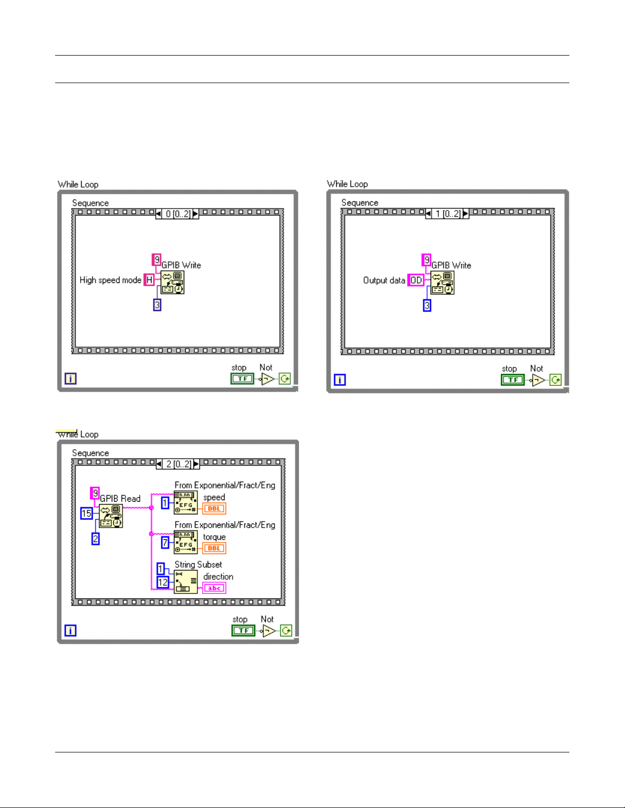
Magtrol offers a comprehensive motor-test software program to satisfy most of your programming needs. To order
your software, call Magtrol Sales at 1-800-828-7844 or 1-716-668-5555.
SIMPLE READ
: L: L
: L
: L: L
abVIEWabVIEW
abVIEW
abVIEWabVIEW
®®
P P
rogramming Examplesrogramming Examples
P
rogramming Examples
P P
rogramming Examplesrogramming Examples
25
Page 32
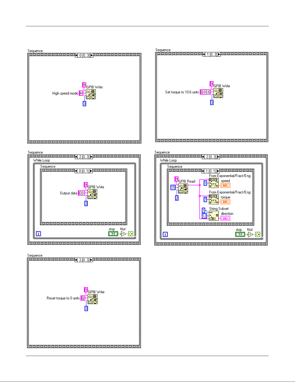
TORQUE STABILIZED
Magtrol Model DSP6000 Dynamometer ControllerAppendix A: LabVIEW Programming Examples
26
Page 33

Magtrol Model DSP6000 Dynamometer Controller Appendix A: LabVIEW Programming Examples
SPEED STABILIZED
27
Page 34
Appendix BAppendix B
Appendix B
Appendix BAppendix B
: Inertia Correction: Inertia Correction
: Inertia Correction
: Inertia Correction: Inertia Correction
INERTIAL EFFECT ON MOTOR TEST DATA
A major advantage of the DSP6000 is its ability to obtain
full motor performance data (free run to locked rotor)
by continuous load application with an absorption
dynamometer. Data acquisition is fast, resulting in
minimal motor I2R losses, and loading characteristics
simulate actual end-use applications.
When a motor is accelerating or decelerating, the
measured torque is the sum of the true motor torque ±
the inertial torque, or stored energy, of the system.
Unless inertial torque is excluded, motor performance
will vary in proportion to the rate of acceleration or
deceleration.
This type of error can produce problematic test results.
For example, during rapid deceleration, system inertia
can produce apparent efficiency greater than 1.0. This
error may occur if output power is divided by input
power without extracting the stored energy in the
system.
4. Immediately program your DSP6000 (Nddddd) to
a speed equal to the dynamic speed value. When
the speed stabilizes, use this as the static torque
value.
CF = Dynamic Torque - Static Torque
To correct your data, subtract the CF from each torque
point obtained during the ramp.
Example:
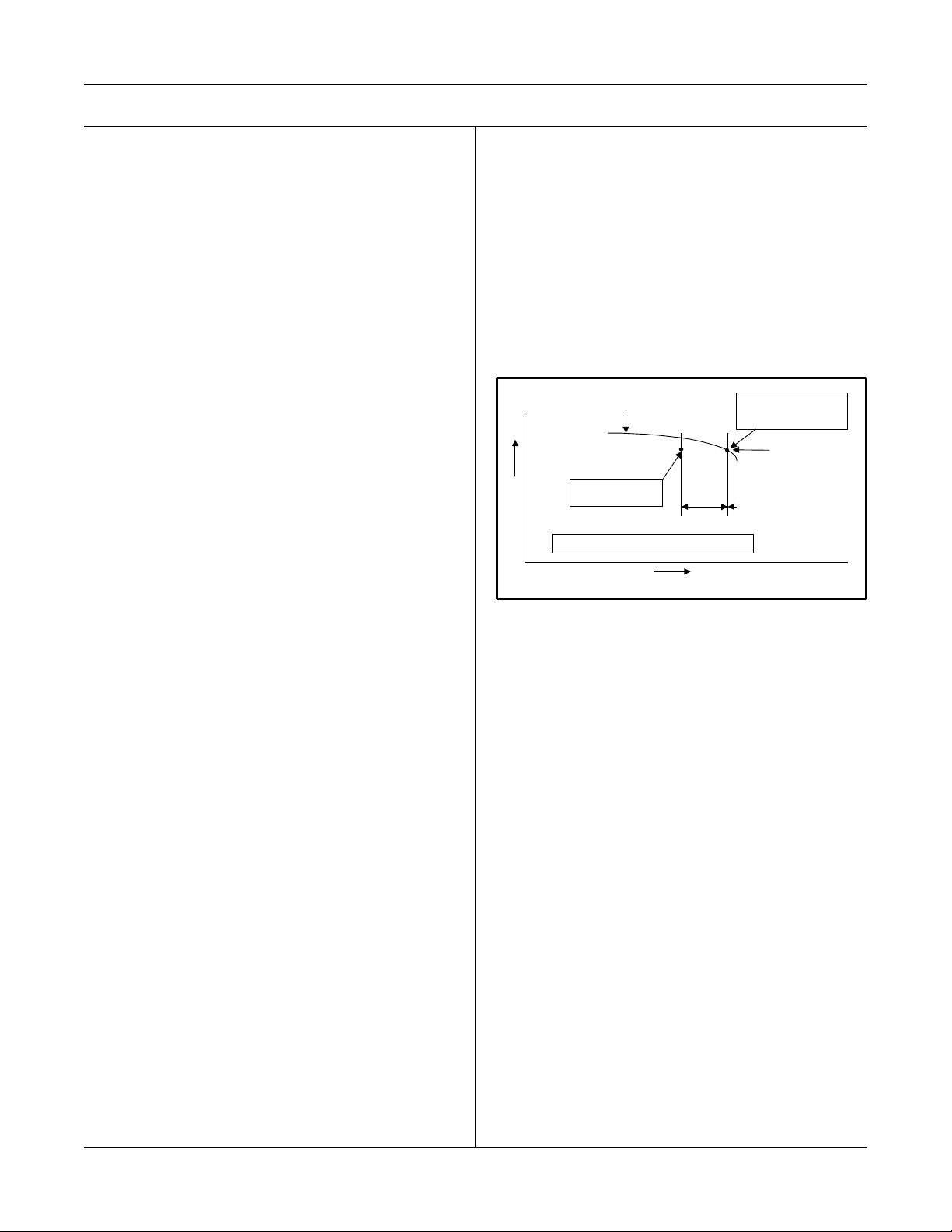
SPEED VS TORQUE
FR
0
CURVE WITH CONSTANT
DECELERATION
S
P
E
E
D
STATIC TORQUE
CF = DIFFERENCE IN TORQUE
VALUE
TORQUE
DYNAMIC
TORQUE VALUE
.78 OF FR
DIFFERENCE IN TORQUE
Since "inertial effect" is only a factor when speed is
changing, and because inertial torque is proportional to
the rate of change, inertial value may be expressed as a
unit of torque per change in RPM in a given period of
time. With the DSP6000, properly adjusted PID values
yield constant change in RPM so that the inertial torque
can be expressed as a constant.
PROCEDURE FOR INERTIA CORRECTION
1. Determine the torque Correction Factor (CF) as
follows:
• Adjust the PID loop properly
• Establish a torque value equal to the inertial
torque.
2. Use the "Program Down" command (PD#) to ramp
to 75% of the free-run speed.
3. Select a data point on the performance curve where
speed will be approximately 78% of the free-run
speed. Let this represent the dynamic speed-torque
value.
KEY CONDITIONS
• Select appropriate value. The test point
selection of 78% is typical for an induction
motor. Use a value in the linear portion of the
motor curve where there is a substantial torque
change with speed.
• Acquire data rapidly. Rapid data acquisition
is necessary so that motor heating does not
degrade performance by adding a false
difference between the static and dynamic
torque values.
• Use a regulated power source. The input line
voltage must be stable for the time necessary
to perform the test. Torque varies by the square
of the change in line voltage.
• Obtain new CF value for various
deceleration/ acceleration rates. The CF is
only valid for its specific ramp rate. To calculate
other CF rates, use the following equation:
CF
= (CF
new
/ramp rate) X new ramp rate
old
28
Page 35
Appendix CAppendix C
Appendix C
Appendix CAppendix C
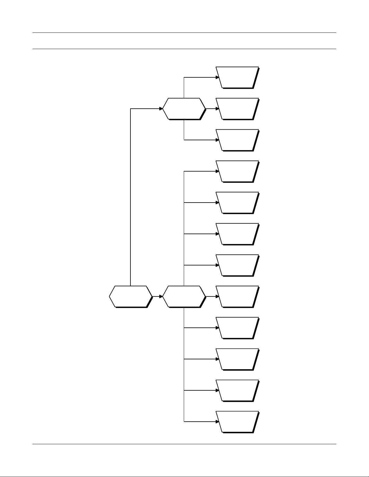
DYNO SETUP MENU
: F: F
: F
: F: F
ront Pront P
ront P
ront Pront P
anel/Display Menu Flow Chartsanel/Display Menu Flow Charts
anel/Display Menu Flow Charts
anel/Display Menu Flow Chartsanel/Display Menu Flow Charts
6000 bit
ENCODER:
600 bit
60 bit
N.m
N.cm
N.mm
kg.cm
DYNO
SETUP:
INPUT
UNITS:
g.cm
lb.ft.
lb.in.
oz.ft.
oz.in.
29
Page 36
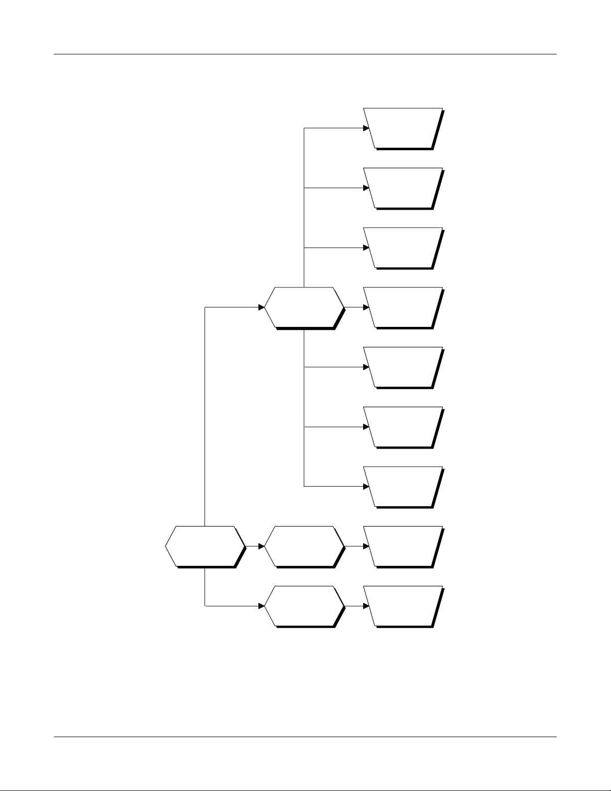
COM SETUP MENU
Magtrol Model DSP6000 Dynamometer ControllerAppendix C: Front Panel/Display Menu Flow Charts
19200
9600
4800
COM SETUP:
RS-232
BAUD:
GPIB
ADDRESS:
2400
1200
600
300
0 - 15
30
CONTRAST:
0 - 3
Page 37
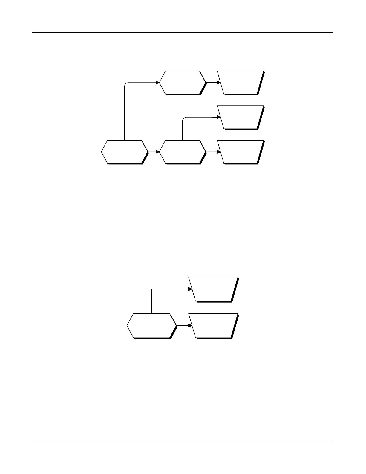
Magtrol Model DSP6000 Dynamometer Controller Appendix C: Front Panel/Display Menu Flow Charts
AUX SETUP MENU
POWER UNITS MENU
SCALE:
AUX SETUP: DISPLAY: OFF
0 - 10000
UNITS/VOLT
ON
POWER UNITS:
W
Hp
31
Page 38
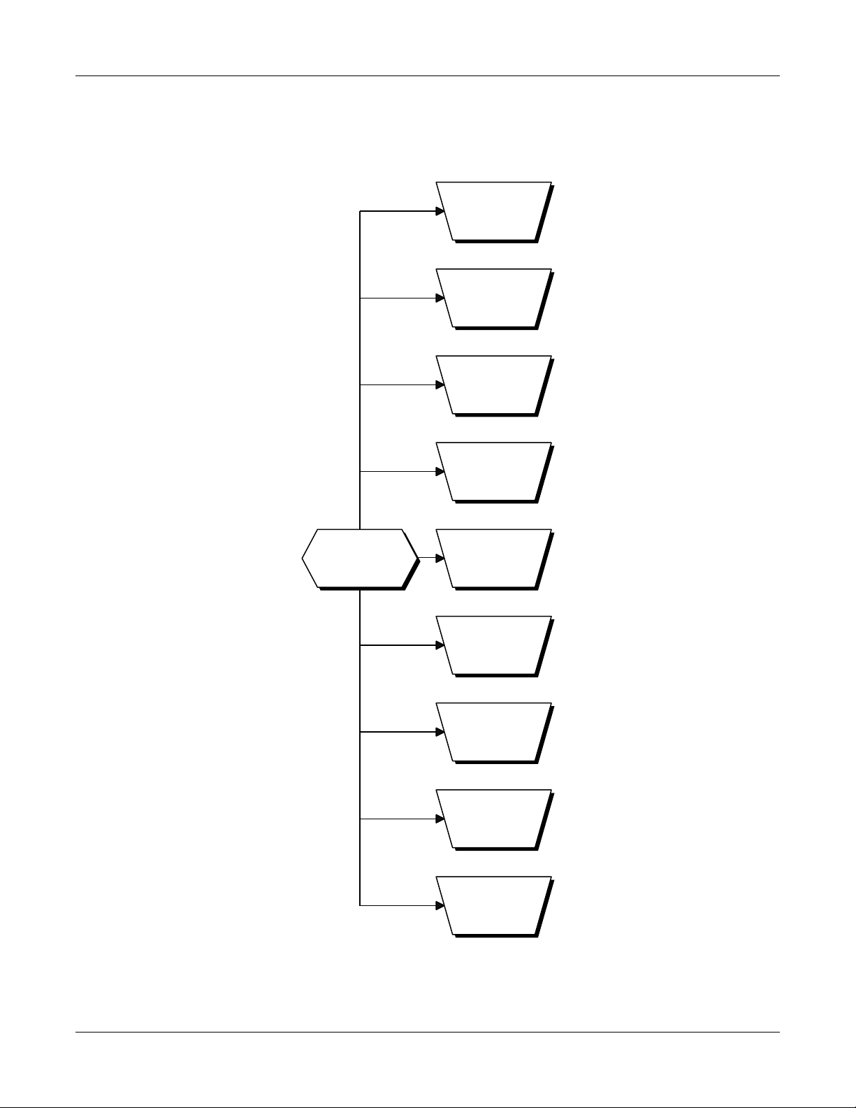
TORQUE UNITS MENU
Magtrol Model DSP6000 Dynamometer ControllerAppendix C: Front Panel/Display Menu Flow Charts
N.m
N.cm
N.mm
TORQUE
UNITS:
kg.cm
g.cm
lb.ft.
lb.in.
oz.ft.
32
oz.in.
Page 39
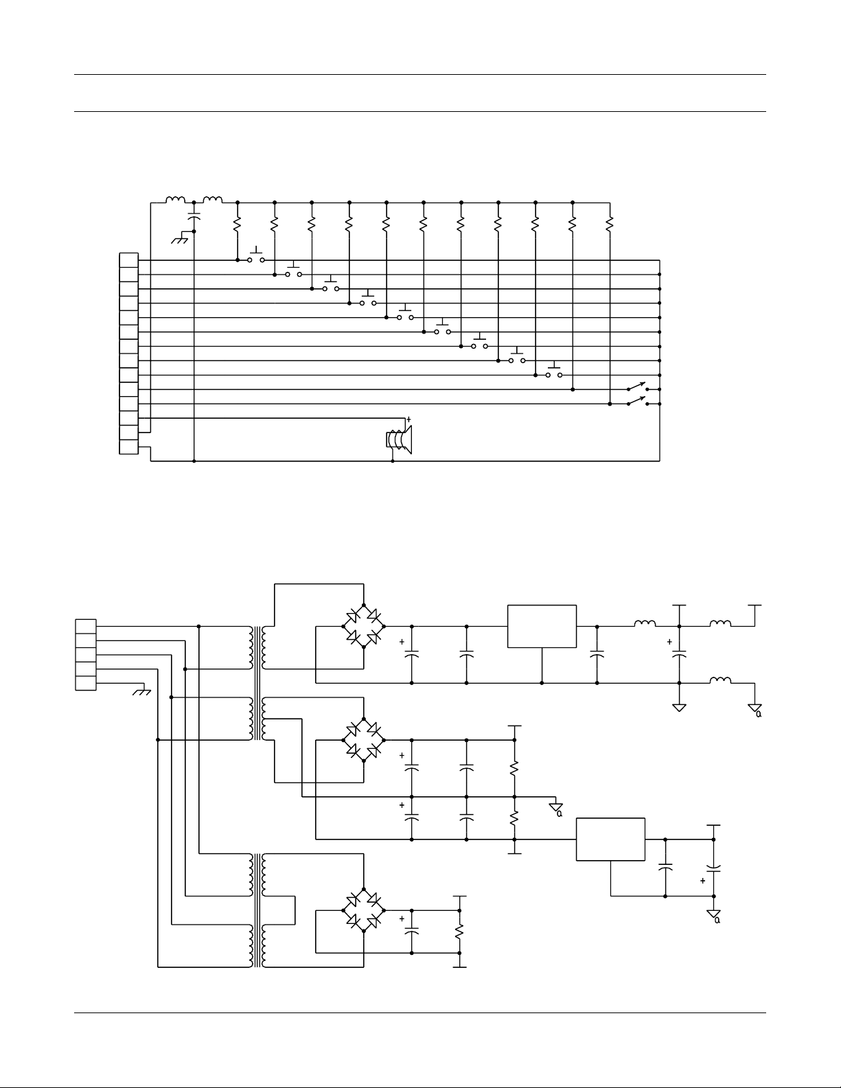
Appendix DAppendix D
Appendix D
Appendix DAppendix D
ENCODER/SWITCH BOARD
C1
: Schematics: Schematics
: Schematics
: Schematics: Schematics
J1
(PB0)
1
(PB1)
2
(PB2)
3
(PB3)
4
(PB4)
5
(PB5)
6
(PB6)
7
(PB7)
8
(PB8)
9
(PB9)
10
(PB10)
11
(AUDIO)
(+ 5V)
(GND)
12
13
14
POWER SUPPLY
J1
1
2
3
4
5
22K 22K 22K 22K 22K 22K 22K 22K 22K 22K 22K
SW1
TX1
1
3
4
6
14A-30-515
12
11
9
8
7
SW2
SW3
PD05
PD05
SW4
SW5
BR1
BR2
SW6
SPKR1
C19
4700
C17
1000
R7R6R5R4R3R2R1 R8 R9 R10 R11
SW7
SW8
C23
0.1
C22
0.1
SW9
U1
LM340T5
IN OUT
COM
+25V
R21
5.1K
A
B
SW10
C23
0.1
(ROTARY ENCODER)
+5VD +5VA
L1
1uH
C2
1.0
d
L2
1uH
L3
1uH
TX2
1
3
4
6
14A-56-28
7
9
10
12
PE05
BR3
C18
1000
C25
4700
+35V
COM
C21
0.1
R23
3.3K
-25V
R22
5.1K
U8
LM320T5
IN OUT
COM
C24
0.1
-5VA
C20
1
33
Page 40
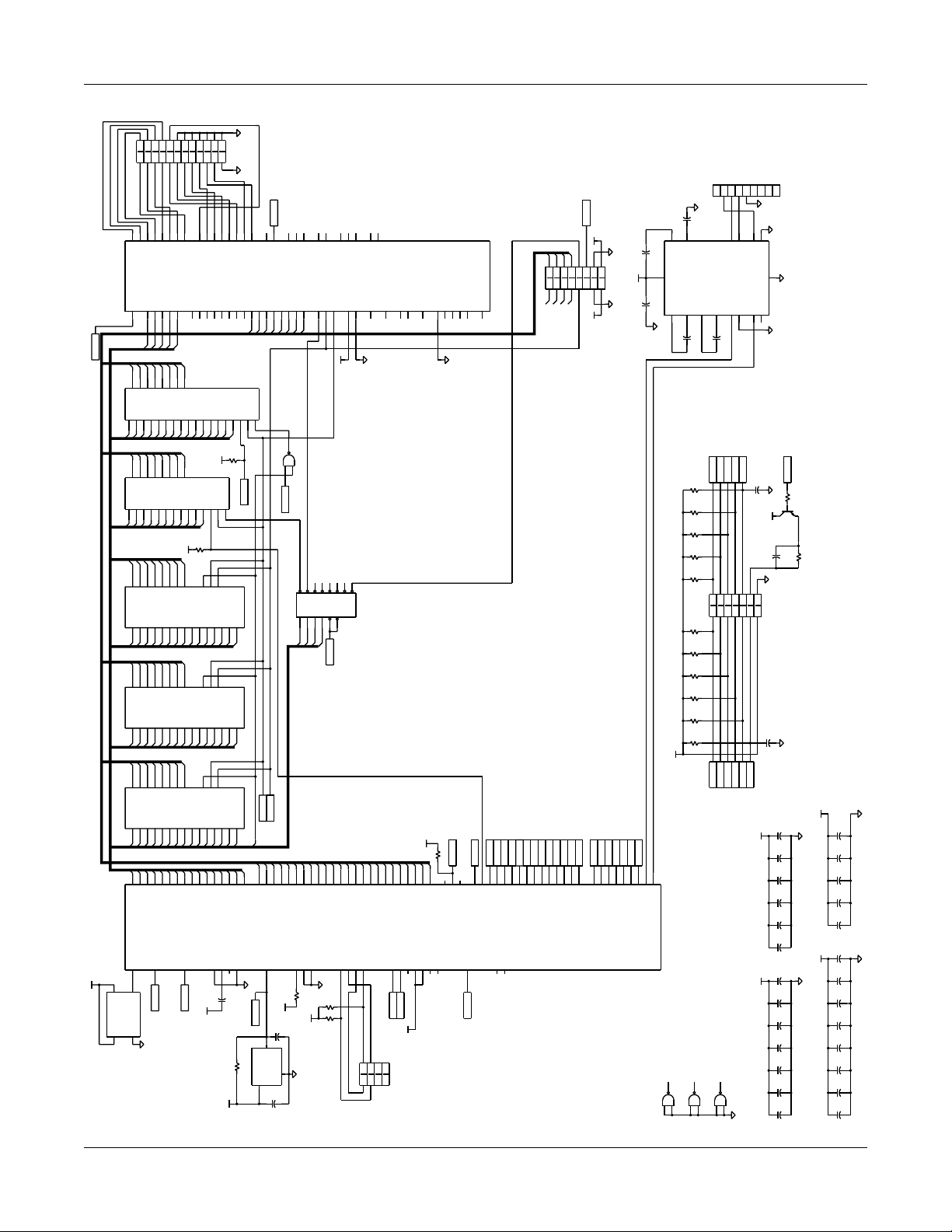
Magtrol Model DSP6000 Dynamometer ControllerAppendix D: Schematics
+5VD
RESET~
U5
J8
DIO8
RESET
U13
6717161819
D1D2D0
U6
10
10911
I/O0
A0
A1
8
7
D21
D23
12
DQ0A0
243
1
D15
D13
12
A0
243
1
D3
11
DQ0 DQ0
A0A1A3
U12 U10U11 U7
1
A15
DSP56002FC40
EXTAL
U4
1
8
5
VDD1OUT
GND
NC/OE
4
14
2
80777471918988
DIO6
DIO7
DIO5
ADDR3
ADDR4
131211
15
O4O6O5
O2O1O3
A37A5
A2A1A0
6
D3D2D1D0D6D4D5
13
I/O3
I/O2
I/O1
A3
4
6
D19
D22
131511
DQ2
DQ3
DQ1A1
A3
A2
26
D8
D14
131511
DQ3
DQ2
DQ1
A2
A1
26
D5D7D1
131512
DQ1
DQ32MHz
A2 DQ2
3
26
A12
A13
A14
XTAL
132
XTAL_OSC
d
1618171315
46513
DIO3
DIO2
DIO4
ADDR2
ADDR0
ADDR1
D6D7D3D5D4
171618
O7
A4
A6A7A9
4
598
14
161517
I/O4
I/O5A6I/O6
A5
A4
3A25
2
D16
D18
D17
16
DQ5A5
DQ6
A4 DQ4
A6DQ6
25524
D11
D10
D9
16
DQ4A3DQ5A5
A4DQ4
A6A7A8
25524
D2D0D6
D417
181916
DQ6
A5 DQ5
A4
A6
452
25
74
7782788083
766171
A9
A11
A10
92
DIO1
DATA15
19
O8
A8
253232421
D7
I/O7
A7
A8A9OE
1
23
22
+5VD
D20
191817
DQ7A7
A8
D12
191817
DQ7
DQ7
A8A7A9
24
72
73
A8
CKOUT
123
40MHz
21
10121178
9
79
70
819576
IFC
REN
DATA13
DATA14
67954947501011
3215
A10
A11
A10
WE
211918
22K
R43
E
G
A9
A10
7236
8
22
20
E
G
A10
A9
7236
8
22
20
E
G
A10
8
65
68
A6
A5
126
+5VD
2324201922
IEEE488
85
82
84
DAV
NRFD
NDAC
DATA10
DATA12
DATA11
A13CEA12
A14
27
26222
R20
+5VDW
CE
AT28C16E-20SC
20
272220
A13
A1127
A12
21910
W
A11
A12
A13
21910
27
W
A13
A11
A12
967
211023
64
63
A3
A4A7A1
A2
PCAP
PLOCK
CKP
128
130
131
0.012
C10
R17
+5VD
dd
73
EOI
ATN
SRQ
DATA7
DATA6
DATA9
DATA8
OE/VPP
A15
MBM27C512
1
20
22K
PAGE
A14
MCM6206BAEJ25
A14
MCM6206BAEJ25
RD~
A14
MCM6206BAEJ25
A15
60
118
117
A0
D22
D23
PINIT
d
125
RESET~
1
2.2K
INPUT
U3
2
40MHz
XTAL1
XTAL0
DATA5
DATA4
WR~
115
D21
RESET
C6
RES
GND
C81
KEYCLK
DATA2
DATA3
434439
3
74HC00
1
2
DS~
114
112
D20
D19
R19
+5VD
0.01
MC34064D
4
0.1
99989666100
21
KEYDQ
KEYRST
DATA0
DATA1
55
424664
U20a
131215
14
Y2
Y1B
U19
AY0
C
3
1
2
A12
A14
A13
111
109
107
108
D16
D17
D18
IRQB
NMI
IRQAMODA/
MODC/
MODB/
119
121
120
22K
+5VD
d
TADCS
LADCS
Y3
G1
6
A15
106
D15
D14
d
R15
R18
23
28
REM
TRIG
ABUS
RDWRCS
623414
63
+5VD
9711
10
Y6Y5Y74Y4G2A
G2B
5
DS~
103
104D996
100
101
D12
D13
D11
DSO
DSI/OS0
53
22K
22K
DSP & MEMORY
20511
DCAS
ABUS_OE
BBUS_OE
CPUACC
BBUS
74HC138
D10
DSCK/OS1
515052
J3
DACK
DRQ
323322
D2D3D1D5D4
WR
RDDRBN
RD~
WR~
+5VD
HEADER_8
85888790915584
4247444146
+5VD
WTBGBR
434054
26
R72
D0
PAGED
22K
59
BS
RDY1
INTR
38
d
93
94
95
D8
D7
8
6
4
2
7
5
3
1
BURST_RD
FIFO_RDY
SWAP
30
31
d
DS~
57138
DS
PS
X/Y
MODE
532952
PAGE
HACK/PB14
TIO
39
TIO
TNT4882
NC
BUSY
PB10
PB11
12106D64
HA2/PB10
HEN/PB12
HR/W/PB11
HREQ/PB13
nc1
nc2
49
PB8
PB9
141715
7
H7/PB7
HA0/PB8
HA1/PB9
PB7
J4
PB5
PB6
H5/PB5
H6/PB6
D4
D7
PB4
18
H4/PB4
D2D0D6
43
D3D5D1
PB2
PB3
23
H3/PB3
H2/PB2
862
751
PB1
PB0
242119
H1/PB1
H0/PB0
BUSY
+5VD
1211
13159
+5VD
STD
38
STD/PC8
d
161410
DISPLAY
HEADER_16
d
FSI
SRD
SCK
31
SC2/PC5
SCK/PC6
SRD/PC7
DPB
L/R
353228
29
SC0/PC3
SC1/PC4
0.1
C76
+5VD
0.1
C69
DPA
263325
TXD/PC1
RXD/PC0
SCLK/PC2
16
U21
d
6
74HC00
4
2
1
5
V+
VCC
C1+
+5VD
U20b
C53
6
3
C77
0.1
V-
C1-
0.1
22K
R13
22K
R12
22K
R11
22K
R10
22K
R9
22K
R1
22K
R2
22K
R3
22K
R4
22K
R5
22K
R6
8
74HC00
10
9
d
C2+
4115
U20c
J10
C68
J2
74HC00
PB1
2
PB0
12
C2-
0.1
PB3
468
PB2
14
13
45213
14
7
TX1OUT
TX2OUT
TX1IN
TX2IN
10
PB7
PB5
531
7
PB6
PB4
U20d
d
PB9
PB8
896
7
RS232
d
d
8
13
RX1IN
RX2IN
MAX232CSE
d
GND
15
RX1OUT9RX2OUT
12
dd
PB11
C7
0.001
3.3K
R16
Q1
+5VD
MMBT2222
+
1.0
C79
R14
d
141210
11139
KEYPAD
HEADER_14
C1
0.001
d
PB10
C39
0.1
+5VD
C38
0.1
C35
0.1
C29
0.01
C30
0.01
3 x MCM6206BAEJ25
C32
0.01
C5
0.1
+5VD
0.1
C14
C4
0.01
C9
0.01
C15
0.01
DSP56002FC40
C12
0.01
C8
0.1
330
d
d
+5VD
C13
C72
XTAL_OSC
C71
74HC138
C16
C11
C48
+5VD
C45
C37
C58
C36
TNT4882 27C512
C73
C75
C74
d
0.1
0.1
74HC00
0.1
0.1
AT28C16
0.1
0.1
d
0.1
0.1
0.1
0.1
0.1
0.1
0.1
34
Page 41
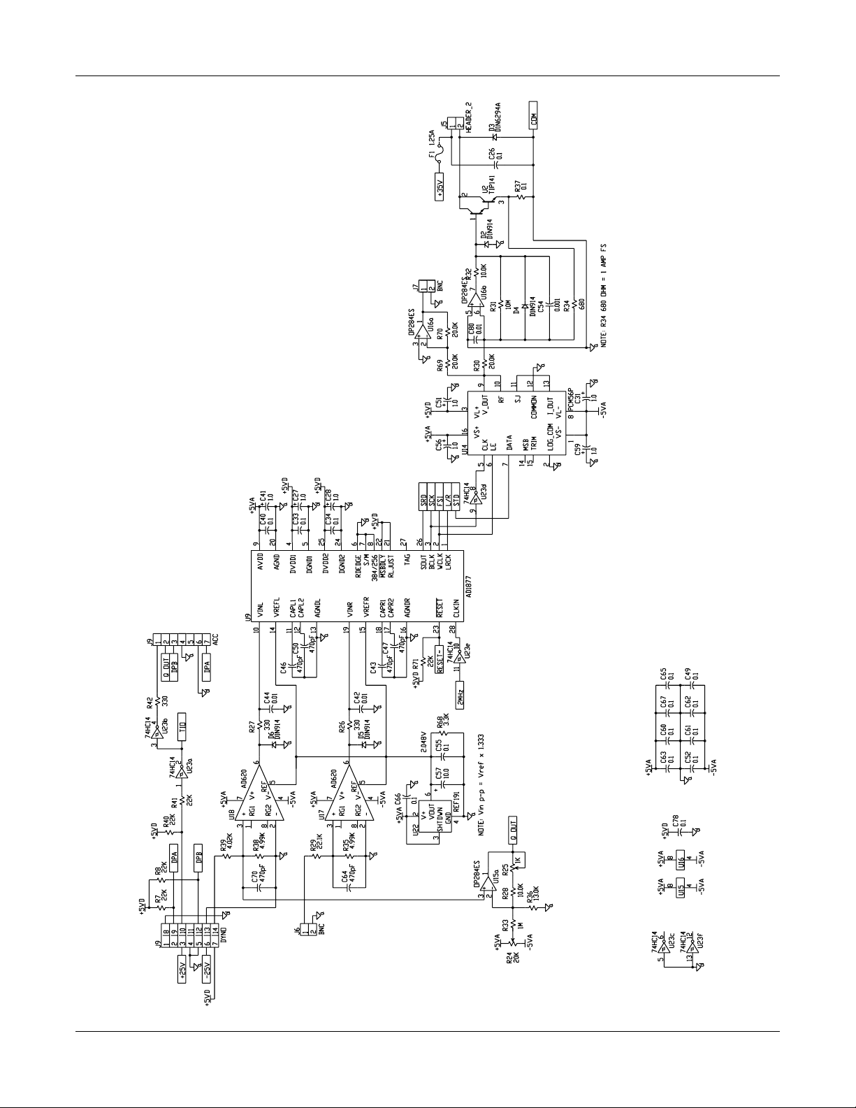
Magtrol Model DSP6000 Dynamometer Controller Appendix D: Schematics
ANALOG I/O
35
Page 42

GlossarGlossar
Glossar
GlossarGlossar
BNC ............................................................................. bayonet, locking-type connector
CCW ............................................................................counterclockwise (turn to left)
CF ................................................................................ correction factor (inertia correction factor)
CR ................................................................................ carriage return
CW ............................................................................... clockwise (turn to right)
D .................................................................................. derivative
D/A .............................................................................. digital to analog converter
DMM ........................................................................... digital multimeter
FR ................................................................................ free-run speed
GPIB (General Purpose Interface Bus) ....................... parallel interface port; interchangeable with IEEE-488
Hp ................................................................................ horsepower; measure of mechanical power
Hz ................................................................................ hertz; frequency
I .................................................................................... integral
y of Abbreviations and Ty of Abbreviations and T
y of Abbreviations and T
y of Abbreviations and Ty of Abbreviations and T
ermserms
erms
ermserms
I/O ................................................................................ input/output
LF ................................................................................ line feed
local ............................................................................. manual control (use front panel controls)
mVDC.......................................................................... millivolts DC
N .................................................................................. speed
NEMA ......................................................................... National Electrical Manufacturers Association
P ................................................................................... proportional; proportional gain
PID ............................................................................... proportional, integral, derivative
PMDC .......................................................................... permanent magnet DC
Q .................................................................................. torque
remote .......................................................................... computer control (uses programmed controls from computer)
RPM............................................................................. revolutions per minute
SI.................................................................................. Systeme Internationale units of measure
S/s ................................................................................ samples per second
V .................................................................................. volts; typically AC
VDC............................................................................. volts DC
36
Page 43

Magtrol Limited WMagtrol Limited W
Magtrol Limited W
Magtrol Limited WMagtrol Limited W
Magtrol, Inc. warrants its products to be free from defects in material and workmanship under normal use and
service for a period of one (1) year from the date of shipment. Software is warranted to operate in accordance with
its programmed instructions on appropriate Magtrol instruments. This warranty extends only to the original purchaser
and shall not apply to fuses, computer media, or any other product which, in Magtrol’s sole opinion, has been
subject to misuse, alteration, abuse or abnormal conditions of operation or shipping.
Magtrol’s obligation under this warranty is limited to repair or replacement of a product which is returned to the
factory within the warranty period and is determined, upon examination by Magtrol, to be defective. If Magtrol
determines that the defect or malfunction has been caused by misuse, alteration, abuse or abnormal conditions of
operation or shipping, Magtrol will repair the product and bill the purchaser for the reasonable cost of repair. If the
product is not covered by this warranty, Magtrol will, if requested by purchaser, submit an estimate of the repair
costs before work is started.
To obtain repair service under this warranty, purchaser must forward the product (transportation prepaid) and a
description of the malfunction to the factory. The instrument shall be repaired at the factory and returned to purchaser,
transportation prepaid. MAGTROL ASSUMES NO RISK FOR IN-TRANSIT DAMAGE.
THE FOREGOING WARRANTY IS PURCHASER’S SOLE AND EXCLUSIVE REMEDY AND IS IN LIEU OF
ALL OTHER WARRANTIES, EXPRESSED OR IMPLIED, INCLUDING BUT NOT LIMITED TO ANY IMPLIED
WARRANTY OF MERCHANTABILITY, OR FITNESS FOR ANY PARTICULAR PURPOSE OR USE.
MAGTROL SHALL NOT BE LIABLE FOR ANY SPECIAL, INDIRECT, INCIDENTAL, OR CONSEQUENTIAL
DAMAGES OR LOSS WHETHER IN CONTRACT, TORT, OR OTHERWISE.
arrantyarranty
arranty
arrantyarranty
CLAIMS
Immediately upon arrival, purchaser shall check the packing container against the enclosed packing list and shall,
within thirty (30) days of arrival, give Magtrol notice of shortages or any nonconformity with the terms of the order.
If purchaser fails to give notice, the delivery shall be deemed to conform with the terms of the order.
The purchaser assumes all risk of loss or damage to products upon delivery by Magtrol to the carrier. If a product is
damaged in transit, PURCHASER MUST FILE ALL CLAIMS FOR DAMAGE WITH THE CARRIER to obtain
compensation. Upon request by purchaser, Magtrol will submit an estimate of the cost to repair shipment damage.
Page 44

70 Gardenville Parkway ! Buffalo, New York 14224
Phone: (716) 668-5555 ! (800) 828-7844 Fax: (716) 668-8705
Web site: www.magtrol.com ! E-mail: [email protected]
MOTOR TESTING EQUIPMENT ! HYSTERESIS BRAKES AND CLUTCHES
 Loading...