


Magnetek Quattro DC Elevator Drive, TM7310rev01 User Manual
r
Quattro
™
DC Elevator Drive
Technical Manual
TM7310 rev 01
© 2006 Magnetek Elevato

WARRANTY Standard products manufactured by the Company are warranted to be free from
defects in workmanship and material for a period of one year from the date of
shipment, and any products which are defective in workmanship or material will be
repaired or replaced, at the Company’s option, at no charge to the Buyer. Final
determination as to whether a product is actually defective rests with the Company.
The obligation of the Company hereunder shall be limited solely to repair or replace,
at the Company’s discretion, products that fall within the foregoing limitations, and
shall be conditioned upon receipt by the Company of written notice of any alleged
defects or deficiency promptly after discovery and within the warranty period, and in
the case of components or units purchased by the Company, the obligation of the
Company shall not exceed the settlement that the Company is able to obtain from the
supplier thereof. No products shall be returned to the Company without its prior
consent. Products which the company consents to have returned shall be shipped
prepaid f.o.b. the Company factory. The Company cannot assume responsibility or
accept invoices for unauthorized repairs to its components, even though defective.
The life of the products the Company depends, to a large extent, upon type of usage
thereof and THE COMPANY MAKES NO WARRANTY AS TO FITNESS OF ITS
PRODUCTS FOR THE SPECIFIC APPLICATIONS BY THE BUYER NOR AS TO
PERIOD OF SERVICE UNLESS THE COMPANY SPECIFICALLY AGREES
OTHERWISE IN WRITING AFTER PROPOSED USAGE HAS BEEN MADE KNOWN
TO IT.
This warranty does not apply to experimental products for which no warranty is made
or given and Buyer waives any claim thereto.
THE FOREGOING WARRANTY IS EXCLUSIVE AND IN LIEU OF ALL OTHER
WARRANTIES, EXPRESSED OR IMPLIED, INCLUDING, BUT LIMITED TO, ANY
WARRANTY OF MECHANTIBILITY OR OF FITNESS FOR A PARTICULAR
PURPOSE AND BUYER HEREBY WAIVES ANY AND ALL CLAIMS THEREFORE.
LIMITATIONS IN NO EVENT SHALL MAGNETEK BE LIABLE FOR LOSS OF PROFIT,
OF LIABILITY INDIRECT, CONSEQUENTIAL OR INCIDENTAL DAMAGES WHETHER
ARISING OUT OF WARRANTY, BREACH OF CONTRACT OR TORT.
QUATTRO is a trademark of Magnetek, Inc.
All rights reserved. No part of this publication may be reproduced or used in any form or by any means - graphic, electronic, or
mechanical including photocopying, recording, taping, or information storage and retrieval systems - without written permission
of the publisher.
© 2007 Magnetek, Inc.

Table of Contents
Introduction.............................................................................................................10
Drive Ratings and Specifications ....................................................................................................... 10
Software Operating Features............................................................................................................. 10
Drive Model Numbers ........................................................................................................................ 11
Quattro startup guide .............................................................................................12
Initial Inspection ................................................................................................................................. 12
Grounding considerations.................................................................................................................. 13
Initial adjustments after power up ...................................................................................................... 13
Interconnections.....................................................................................................15
Drive Sequencing....................................................................................................21
NORMAL operating sequence........................................................................................................... 21
ABNORMAL Operation Sequence.....................................................................................................22
Quattro Pre-Charge ........................................................................................................................... 22
Drive Operation and Feature Overview.................................................................23
Analog Velocity Follower.................................................................................................................... 23
Preset Speed & Profile Generator ..................................................................................................... 23
Serial Link Follower............................................................................................................................ 23
Pre-Torque......................................................................................................................................... 23
Torque Feed Forward ........................................................................................................................ 23
Torque/Current Ramp-Down ............................................................................................................. 23
Motor Field Current Control and Field weakening ............................................................................. 24
DSPR ................................................................................................................................................. 24
Over-Speed Test................................................................................................................................ 24
Fault & Alarm Reset........................................................................................................................... 24
Electronic Motor Over-Load............................................................................................................... 24
Armature Voltage Feedback .............................................................................................................. 24
Status Indicator Lights ....................................................................................................................... 25
MONITOR / Adjust / Set-up Parameters:...........................................................................................25
Parameters ..............................................................................................................26
Parameter Introduction ...................................................................................................................... 26
Menu Navigation ................................................................................................................................ 27
Parameter Tree.................................................................................................................................. 28
Adjust A0 menu.......................................................................................................30
Drive A1 submenu ............................................................................................................................. 30
S-Curves A2 submenu....................................................................................................................... 39
Multistep Ref A3 submenu................................................................................................................. 41
Motor Side Power Convert A4 submenu ........................................................................................... 43
Line Side Power Converter A5 submenu........................................................................................... 46
Motor Parameters A6 submenu......................................................................................................... 47
Configure C0 menu.................................................................................................50
User Switches C1 submenu .............................................................................................................. 50
Logic Inputs C2 submenu .................................................................................................................. 61
Logic Outputs C3 submenu ............................................................................................................... 63
Analog Outputs C4 submenu............................................................................................................. 65
Display D0 menu.....................................................................................................66
Elevator Data D1 submenu................................................................................................................ 66
MS Power Data D2 submenu ............................................................................................................ 68
1

LS Power Data D3 submenu ............................................................................................................. 69
Utility U0 menu........................................................................................................70
Fault F0 menu..........................................................................................................76
Maintenance ............................................................................................................78
Maintenance Overview ...................................................................................................................... 78
Drive Servicing................................................................................................................................... 78
Troubleshooting......................................................................................................79
Appendix..................................................................................................................95
Auto Tune Procedure......................................................................................................................... 95
Inertia Calculation .............................................................................................................................. 96
EMC Compliance ............................................................................................................................... 97
Re-Assembly Procedure for 200A / 250A drives ............................................................................... 98
Control Power Consumption............................................................................................................ 102
Watts Loss ....................................................................................................................................... 102
Input / Output Ratings ...................................................................................................................... 102
Wire Terminal Specs........................................................................................................................ 103
Dimensions / Weights ...................................................................................................................... 104
Component Locations ...................................................................................................................... 109
Spare Parts Quattro DC Drive ......................................................................................................... 116
Index.......................................................................................................................119
2

Quattro DC Quick Parameter Reference
Sub
menu
A1 Drive A1 Submenu – See Drive A1 submenu on page 30.
Parameter Units Range Default
A1 CONTRACT CAR SPD
A1 CONTRACT MTR SPD RPM 30.0 – 3000.0 1130.0
A1 RESPONSE rad/sec 1.0 – 20.0 10.0
A1 INERTIA sec 0.25 – 50.00 2.00
A1 INNER LOOP XOVER rad/sec 0.1 – 20.0 2.0
A1 CURRENT LIMIT % 0.0 – 275.0 200
A1 GAIN REDUCE MULT % 10 – 100 100
A1 GAIN CHNG LEVEL % of rated spd 0.0 – 100.0 100.0
A1 TACH FILTER BW rad/sec 1 – 100 100
A1 TACH RATE GAIN none 0.0 – 30.0 0.0
A1 SPD PHASE MARGIN degrees 45 – 90 80
A1 RAMPED STOP TIME sec 0.00 – 2.50 0.20
A1 CONTACT FLT TIME sec 0.10 – 5.00 0.50
A1 BRAKE PICK TIME sec 0.00 – 5.00 1.00
A1 BRAKE HOLD TIME sec 0.00 – 5.00 0.20
A1 OVERSPEED LEVEL % of contract spd 90.0 – 150.0 115.0
A1 OVERSPEED TIME sec 0.00 – 9.99 1.00
A1 OVERSPEED MULT % 100.0 – 150.0 125.0
A1 ENCODER PULSES PPR 600 – 10000 5000
A1 SPD DEV LO LEVEL % of contract spd 0.1 – 20.0 10.0
A1 SPD DEV TIME sec 0.00 – 9.99 0.50
A1 SPD DEV HI LEVEL % of contract spd 0.0 – 99.9 10.0
A1 SPD COMMAND BIAS volts 0.00 – 6.00 0.00
A1 SPD COMMAND MULT none 0.90 – 5.00 1.00
A1 EXT TORQUE BIAS volts -6.00 – +6.00 0.00
A1 EXT TORQUE MULT none -10.00 – +10.00 1.00
A1 ZERO SPEED LEVEL % of contract spd 0.00 – 99.99 1.00
A1 ZERO SPEED TIME sec 0.00 – 9.99 0.10
A1 UP/DWN THRESHOLD % of contract spd 0.00 – 9.99 1.00
A1 ANA 1 OUT OFFSET % -99.9 – +99.9 0.0
A1 ANA 2 OUT OFFSET % -99.9 – +99.9 0.0
A1 ANA 1 OUT GAIN none 0.0 – 10.0 1.0
A1 ANA 2 OUT GAIN none 0.0 – 10.0 1.0
A1 FLT RESET DELAY sec 0 – 120 5
A1 FLT RESETS/HOUR faults 0 – 10 3
A1 UP TO SPD LEVEL % of contract spd 0.00 – 110.00 80.00
A1 RUN DELAY TIMER sec 0.00 – 0.99 0.00
A1 AB ZERO SPD LEV % 0.00 – 2.00 0.00
A1 AB OFF DELAY sec 0.00 – 9.99 0.00
A1 CONTACTOR DO DLY sec 0.00 – 5.00 0.00
A1 TRQ LIM MSG DLY sec 0.00 – 10.00 0.50
A1 ROLLBACK GAIN none 1 – 99 1
A1 NOTCH FILTER FRQ Hz 5 – 60 20
A1 NOTCH FILT DEPTH % 0 – 100 0
A1 STNDBY FLD TIME sec 0 – 999 30
A1 DSPR TIME min 0 – 999 120
A1 FULL FIELD TIME min 0 – 99 5
fpm 0.0 – 1500.0 400.0
m/s 0.000 – 8.000 2.000
Site
Setting
3

Quattro DC Quick Parameter Reference
Sub
menu
A2 S-Curves A2 Submenu – See S-Curves A2 submenu on page 39.
Parameter Units Range Default
A2 ACCEL RATE 0
A2 DECEL RATE 0
A2 ACCEL JERK IN 0
A2 ACCEL JERK OUT 0
A2 DECEL JERK IN 0
A2 DECEL JERK OUT 0
A2 ACCEL RATE 1
A2 DECEL RATE 1
A2 ACCEL JERK IN 1
A2 ACCEL JERK OUT 1
A2 DECEL JERK IN 1
A2 DECEL JERK OUT 1
A2 ACCEL RATE 2
A2 DECEL RATE 2
A2 ACCEL JERK IN 2
A2 ACCEL JERK OUT 2
A2 DECEL JERK IN 2
A2 DECEL JERK OUT 2
A2 ACCEL RATE 3
A2 DECEL RATE 3
A2 ACCEL JERK IN 3
A2 ACCEL JERK OUT 3
A2 DECEL JERK IN 3
A2 DECEL JERK OUT 3
ft/s2 0.00 – 7.99 7.99
2
m/s
0.000 – 3.999 2.435
ft/s2 0.00 – 7.99 7.99
2
m/s
0.000 – 3.999 2.435
ft/s3 0.0 – 29.9 0.0
3
m/s
0.000 – 9.999 0.000
ft/s3 0.0 – 29.9 0.0
3
m/s
0.000 – 9.999 0.000
ft/s3 0.0 – 29.9 0.0
3
m/s
0.000 – 9.999 0.000
ft/s3 0.0 – 29.9 0.0
3
m/s
0.000 – 9.999 0.000
ft/s2 0.00 – 7.99 7.00
2
m/s
0.000 – 3.999 2.134
ft/s2 0.00 – 7.99 3.00
2
m/s
0.000 – 3.999 0.090
ft/s3 0.0 – 29.9 8.0
3
m/s
0.000 – 9.999 2.400
ft/s3 0.0 – 29.9 8.0
3
m/s
0.000 – 9.999 2.400
ft/s3 0.0 – 29.9 8.0
3
m/s
0.000 – 9.999 2.400
ft/s3 0.0 – 29.9 8.0
3
m/s
0.000 – 9.999 2.400
ft/s2 0.00 – 7.99 3.00
2
m/s
0.000 – 3.999 0.090
ft/s2 0.00 – 7.99 3.00
2
m/s
0.000 – 3.999 0.090
ft/s3 0.0 – 29.9 8.0
3
m/s
0.000 – 9.999 2.400
ft/s3 0.0 – 29.9 8.0
3
m/s
0.000 – 9.999 2.400
ft/s3 0.0 – 29.9 8.0
3
m/s
0.000 – 9.999 2.400
ft/s3 0.0 – 29.9 8.0
3
m/s
0.000 – 9.999 2.400
ft/s2 0.00 – 7.99 3.00
2
m/s
0.000 – 3.999 0.090
ft/s2 0.00 – 7.99 3.00
2
m/s
0.000 – 3.999 0.090
ft/s3 0.0 – 29.9 8.0
3
m/s
0.000 – 9.999 2.400
ft/s3 0.0 – 29.9 8.0
3
m/s
0.000 – 9.999 2.400
ft/s3 0.0 – 29.9 8.0
3
m/s
0.000 – 9.999 2.400
ft/s3 0.0 – 29.9 8.0
3
m/s
0.000 – 9.999 2.400
Site
Setting
4

Quattro DC Quick Parameter Reference
Sub
menu
Parameter Units Range Default
A3 Multistep Ref A3 Submenu – See Multistep Ref A3 submenu on page 41.
A3 SPEED COMMAND 1
A3 SPEED COMMAND 2
A3 SPEED COMMAND 3
A3 SPEED COMMAND 4
A3 SPEED COMMAND 5
A3 SPEED COMMAND 6
A3 SPEED COMMAND 7
A3 SPEED COMMAND 8
A3 SPEED COMMAND 9
A3 SPEED COMMAND 10
A3 SPEED COMMAND 11
A3 SPEED COMMAND 12
A3 SPEED COMMAND 13
A3 SPEED COMMAND 14
A3 SPEED COMMAND 15
ft/min -3000.0 – +3000.0 0.0
m/sec -16.000 – +16.000 0.000
ft/min -3000.0 – +3000.0 0.0
m/sec -16.000 – +16.000 0.000
ft/min -3000.0 – +3000.0 0.0
m/sec -16.000 – +16.000 0.000
ft/min -3000.0 – +3000.0 0.0
m/sec -16.000 – +16.000 0.000
ft/min -3000.0 – +3000.0 0.0
m/sec -16.000 – +16.000 0.000
ft/min -3000.0 – +3000.0 0.0
m/sec -16.000 – +16.000 0.000
ft/min -3000.0 – +3000.0 0.0
m/sec -16.000 – +16.000 0.000
ft/min -3000.0 – +3000.0 0.0
m/sec -16.000 – +16.000 0.000
ft/min -3000.0 – +3000.0 0.0
m/sec -16.000 – +16.000 0.000
ft/min -3000.0 – +3000.0 0.0
m/sec -16.000 – +16.000 0.000
ft/min -3000.0 – +3000.0 0.0
m/sec -16.000 – +16.000 0.000
ft/min -3000.0 – +3000.0 0.0
m/sec -16.000 – +16.000 0.000
ft/min -3000.0 – +3000.0 0.0
m/sec -16.000 – +16.000 0.000
ft/min -3000.0 – +3000.0 0.0
m/sec -16.000 – +16.000 0.000
ft/min -3000.0 – +3000.0 0.0
m/sec -16.000 – +16.000 0.000
A4 Motor Side Power Convert A4 Submenu – See Motor Side Power Convert on page 43.
A4 ARM RESISTANCE ohm 0.0001 – 2.9999 0.5000
A4 ARM INDUCTANCE mH 0.01 – 327.67 15.00
A4 MTR REV VLT LIM % 0.01 – 30.00 4.80
A4 If REG INT GAIN none 0.00 – 30.00 0.90
A4 If REG PROP GAIN none 0.00 – 16.38 6.07
A4 AUTO TUNE MOTOR none
A4 GAIN SELECTION none
A4 GAIN BANDWIDTH A rad/sec 100 – 2000 500
A4 GAIN BANDWIDTH F rad/sec 1 – 40 5
A4 PWM FREQUENCY kHz 2.5 – 16.0 6.0
A4 FAN OFF DELAY sec 0 – 999 180
A4 MAIN FAN CONTROL none
A4 UV-ALARM LEVEL % 80 – 99 90
A4 UV FAULT LEVEL % 50 – 99 80
A4 FLD CARRIER FRQ kHz 3 – 10 3
− Start Autotune?
− manual
− autotune
− auto
− temp
− off
− low
− medium
− high
-
MANUAL
TEMP
Site
Setting
5

Quattro DC Quick Parameter Reference
Sub
menu
Parameter Units Range Default
A5 Line Side Power converter A5 Submenu – See Line Side Power Converter on page 46.
A5 Id REG PROP GAIN none 0.00 – 9.99 0.30
A5 Id REG INTGRL GAIN none 0 – 999 10
A5 Iq REG PROP GAIN none 0.00 – 9.99 0.30
A5 Iq REG INTGRL GAIN none 0 – 999 40
A5 DC BUS REG P GAIN none 0.00 – 9.99 3.00
A5 DC BUS REG I GAIN none 0 – 999 40
A5 INPUT L-L VOLTS volts 110 – 552 480
A5 DC BUS V BOOST volts 15 – 75 30
A5 SW BUS OV LEVEL volts 100 – 850 850
A5 BUS VREF SOURCE none
A5 PLL FILTER FC Hz 0.0 – 150.0 40.0
A5 LS PWM FREQ kHz 2.5 – 16.0 10.0
A6
Motor A6 Submenu – See Motor Parameters A6 submenu on page 47.
A6 MOTOR ID none - -
A6 RATED MOTOR CURR amps 1.0 – 400.0 0.0
A6 ARMATURE VOLTS volts 55 – 600 0
A6 FULL FLD CURRENT amps 1.0 – 40.0 0.0
A6 WEAK FLD CURRENT amps 1.0 – 40.0 0.0
A6 STANDBY FIELD amps 0.0 – 40.0 0.0
A6 FLUX CONFIRM LEV % 25.0 – 99.0 0.0
A6 ARMATURE IR DROP % 0.0 – 25.0 0.0
A6 OVLD START LEVEL % 100 – 150 110
A6 OVLD TIME OUT sec 5.0 – 120.0 60.0
− track line v
− trk vin param
TRK Vin PARAM
C1 User Switches C1 Submenu – See User Switches C1 submenu on page 50.
− analog input
C1 SPD COMMAND SRC none
C1 RUN COMMAND SRC none
C1 FIELD ENA SOURCE none
C1 HI/LO GAIN SRC none
C1 SPEED REG TYPE none
C1 MOTOR ROTATION
C1 ENCODER CONNECT
C1 SPD REF RELEASE
C1 CONT CONFIRM SRC
C1 TACH FILTER
none
none
none
none
none
− multi-step
− ser mult step
− serial
− external tb
− serial
− serial+extrn
− external tb
− serial
− 2-bit serial
− enable on run
− external tb
− serial
− internal
− elev spd reg
− pi speed reg
− external reg
− cemf reg
− forward
− reverse
− forward
− reverse
− reg release
− brake picked
− none
− external tb
− off
− on
MULTI-STEP
EXTERNAL TB
ENABLE ON RUN
INTERNAL
ELEV SPD REG
FORWARD
FORWARD
REG RELEASE
NONE
OFF
Site
Setting
6

Sub
menu
C1
Parameter Units Range Default
User Switches C1 Submenu continued …
C1 PreTorque SOURCE none
C1 PreTorque LATCH
C1 PTorq LATCH CLCK
C1 FAULT RESET SRC none
C1 OVERSPD TEST SRC
C1 BRAKE PICK SRC
C1 BRAKE PICK CNFM none
C1 BRAKE HOLD SRC
C1 RAMPED STOP SEL
C1 RAMP DOWN EN SRC none
C1 BRK PICK FLT ENA
C1 BRK HOLD FLT ENA
C1 EXT TORQ CMD SRC none
C1 DIR CONFIRM
C1 S-CURVE ABORT
C1 ENCODER FAULT
C1 PRIORITY MESSAGE
C1 STOPPING MODE
C1 AUTO STOP
C1 DSPR ENABLE
none
none
none
none
none
none
none
none
none
none
none
none
none
none
none
Quattro DC Quick Parameter Reference
Site
Setting
− none
− analog Input
− serial
− not latched
− latched
− serial
− external tb
− external tb
− serial
− automatic
− external tb
− serial
− internal
− serial
− none
− internal time
− external tb
− internal
− serial
− none
− ramp on stop
− external tb
− run logic
− serial
− disable
− enable
− disable
− enable
− none
− analog input
− serial
− disable
− enable
− disable
− enable
− disable
− enable
− disable
− enable
− immediate
− ramp to stop
− disable
− enable
− disable
− enable
NONE
NOT LATCHED
EXTERNAL TB
EXTERNAL TB
EXTERNAL TB
INTERNAL
NONE
INTERNAL
NONE
EXTERNAL TB
DISABLE
DISABLE
NONE
DISABLE
DISABLE
ENABLE
ENABLE
IMMEDIATE
DISABLE
DISABLE
7
Quattro DC Quick Parameter Reference
Sub
menu
C2
C3 Logic Outputs C3 Submenu – See Logic Outputs C3 submenu on page 63.
Parameter Units Range Default
Logic Inputs C2 Submenu – See Logic Inputs C2 submenu on page 61.
C2 N.C. INPUTS None Hex Number 0x01
C2 LOGIC INPUT 1 TB1(1)
C2 LOGIC INPUT 2 TB1(2)
C2 LOGIC INPUT 3 TB1(3)
C2 LOGIC INPUT 4 TB1(4)
C2 LOGIC INPUT 5 TB1(5)
C2 LOGIC INPUT 6 TB1(6)
C2 LOGIC INPUT 7 TB1(7)
C2 LOGIC INPUT 8 TB1(8)
C2 LOGIC INPUT 9 TB1(9)
LOGIC OUTPUT 1
C3
TB1(25)
LOGIC OUTPUT 2
C3
TB1(26)
LOGIC OUTPUT 3
C3
TB1(27)
LOGIC OUTPUT 4
C3
TB1(28)
LOGIC OUTPUT 5
C3
TB1(29)
LOGIC OUTPUT 6
C3
TB1(30)
LOGIC OUTPUT 7
C3
TB1(31)
C3
SSR1 TB1(21/22) NO FUNCTION
C3
SSR2 TB1(23/24) NO FUNCTION
RELAY COIL 1 TB2
C3
(1/3/5)
RELAY COIL 2 TB2
C3
(8/10/12)
− contact cfirm
− ctr pwr sense
− drive enable
− extrn fault 1
− extrn fault 2
− extrn fault 3
− extrn /flt 4
− fault reset
− field enable
− low gain sel
− mech brk hold
− mech brk pick
− no function
− ospd test src
− alarm
− alarm+flt
− auto brake
− brake hold
− brake pick
− brk hold flt
− brk pick flt
− car going dwn
− car going up
− charge fault
− close contact
− contactor flt
− curr reg flt
− drv overload
− encoder flt
− fault
− flux confirm
− ground fault
− in low gain
− motor trq lim
− mtr overload
− no function
− pre-trq latch
− run
− run down
− run up
− s-curve sel 0
− s-curve sel 1
− ser2 insp ena
− step ref b0
− step ref b1
− step ref b2
− step ref b3
− trq ramp down
− up/dwn
− not alarm
− over curr flt
− overspeed flt
− overtemp flt
− overvolt flt
− ovrtemp alarm
− phase fault
− ramp down ena
− ready 2 start
− ready to run
− regen trq lim
− run commanded
− run confirm
− speed dev
− speed dev low
− speed ref rls
− speed reg rls
− undervolt flt
− up to speed
− uv alarm
− zero speed
CONTACT CFIRM
CTR PWR SENSE
NO FUNCTION
DRIVE ENABLE
RUN
UP/DWN
STEP REF B0
STEP REF B1
FAULT RESET
CLOSE
CONTACT
RUN
COMMANDED
MTR OVERLOAD
ENCODER FLT
FAULT
SPEED REG
RLS
SPEED REG
RLS
NO FUNCTION
NO FUNCTION
Site
Setting
C4 Analog Outputs C4 Submenu – See Analog Outputs C4 submenu on page 65.
ANALOG OUTPUT 1
C4
C4 ANALOG OUTPUT 2
− arm current
− arm voltage
− aux torq cmd
− bus voltage
− est motor spd
− field current
− iarm error
− pretorque ref
− motor mode
− spd rg tq cmd
− speed command
− speed error
− speed feedbk
− speed ref
− tach rate cmd
− tach speed
− torque ref
SPEED REF
SPEED FEEDBK
8

Menu Parameter Unit
D1 Elevator Data Submenu
D1 Speed Command ft/min or m/sec
D1 Speed Reference ft/min or m/sec
D1 Speed Feedback ft/min or m/sec
D1 Speed Error ft/min or m/sec
D1 Pre-Torque Ref % of rated torque
D1 Ext-Torque Cmd % of rated current
D1 Spd Reg Torq Cmd % of rated torque
D1 Tach Rate Cmd % of rated torque
D1 Aux Torque Cmd % of rated torque
D1 Est Inertia Seconds
D1 Rx Com Status 1 = true; 0 = false
D1 Logic Outputs 1 = true; 0 = false
D1 Logic Inputs 1 = true; 0 = false
D2 MS Power Data Submenu
D2 Armature Current Amps
D2 Field Current Amps
D2 Armature Voltage Volts
D2 MS Bus Voltage Volts
D2 Motor Mode None
D2 Torque Ref %
D2 Est Spd Fdbk ft/min or m/sec
D2 Encoder Spd ft/min or m/sec
D2 DS Module Temp °C
D2 LS Module Temp °C
D2 Highest Temp °C
D2 Field IGBT Temp °C
D2 Armature Cur Err Amps
D2 Auto Fld Int none
D2 Auto Fld Prop none
D2 Auto Meas Arm L mH
D2 Auto Meas Arm R Ohm
D2 Auto Field Res Ohm
D2 Auto Field Tc sec
D3 LS Power Data Submenu
D3 LS Pwr Output kW
D3 DC Bus Voltage Volts
D3 DC Bus Volts Ref Volts
D3 LS Overload %
D3 LS Input Current Amps
D3 LS D Axis I %
D3 LS Q Axis I %
D3 LS D Axis Volts %
D3 LS Q Axis Volts %
D3 Input Hz Hz
D3 Input Vab Volts
D3 Input Vca Volts
D3 LS Module Temp °C
Quattro DC Quick Parameter Reference
Menu Parameter Unit
U1 Password U1 Submenu
U1 Enter password U1 New password U1 Password Lockout -
U2 Hidden Items U2 Submenu
U2 Hidden Items Enable -
U3 Units U3 Submenu
U3 Units Selection -
U4 Ovrspeed Test U4 Submenu
U4 Overspeed Test -
U5 Restore Dflts U5 Submenu
U5 Restore Motor Dflts U5 Restore Drive Dflts U5 Restore Utility Dflts -
U6 Motor Side Info U6 Submenu
U6 MS Type U6 MS Code Version U6 MS S/W Date U6 MS S/W Time U6 MS FPGA Version U6 MS Cube ID -
U7 Line Side Info U7 Submenu
U7 LS Type U7 LS Code Version U7 LS S/W Date U7 LS S/W Time U7 LS FPGA Version U7 LS Cube ID -
U8 Hex Monitor U8 Submenu
U8 Hex Monitor -
F1 Active Faults F1 Submenu
F1 Display Active Faults F1 Reset Active Faults -
F2 Faults History F2 Submenu
F2 Display Fault History F2 Clear Fault History F2 Display Fault Counters -
9

Quattro DC Introduction
Introduction
Drive Ratings and Specifications
The Quattro drive is designed for connection to
a 4 wire grounded 3-phase input along with a
single-phase 230 VAC control power input.
Basic Drive Specifications
• 125, 200, 250 amps DC armature output
(Elevator Run Current) at up to 550VDC in
2 basic model sizes
• 150% overload for 60 seconds
• 250% overload for 6 seconds
• Up to 40 ADC motor field control
• <8% utility input current harmonics at full
power (<5% on 125 amp unit)
• Unity Power Factor (1.0 Service Factor)
• 0–45ºC (32–115ºF) ambient temp range
• Fully regenerative operation
• Includes motor armature contactor w/
provision for armature DB resistors
• 4+ Million Start-Stop operating cycles
• (9) 24VDC Programmable Logic Inputs
• (11) Programmable Logic Outputs:
− (7) 24VDC
− (2) Solid-State Relays
− (2) Relays
• 5V or 12V Isolated encoder power source
w/ differential receivers
Service Conditions
• Required: 200-480 VAC, 3-phase, 50/60 Hz
input power, Line Impedance Z < 6%
• Required: 220-240 VAC, single-phase
control power, 50/60 Hz, 3.5/5.5 amps
maximum for 125/200-250 amp drives
respectively
Software Operating Features
The General Purpose Quattro-DC elevator
drive is a four-quadrant torque and speed
regulated motor drive with low power line
harmonic currents and unity power factor. It
can be configured to operate geared and
gearless elevators and lifts. Basic features
include...
• User choice of operating speed reference
(see pg 23)
− External analog reference follower
− Serial link reference follower
− Internal reference generator with
controlled S-Curve smoothing to one of 15
preset speeds
• User choice of ft/min or m/sec speed
programming and display units (see pg 71)
• User choice of input control logic for Run-Up /
Run-Down or Run / Direction relay control
with internal preset speeds (see pg 23)
• User choice of P-I type or MagneTek
exclusive E-Reg, elevator velocity
regulators (see pages 59 and 60)
• Optional CEMF speed regulator for use
during initial construction stage start-up
• Torque Feed-Forward when available from
the car controller (see pg 23)
• Pre-Torque at drive start to reduce roll-back
(see pg 23)
• Controlled torque Ramp-Down to prevent
elevator brake thumping at stops (see pg 23)
• Internal frequency notch filter to reject rope
resonance interference (see pg 38)
• Closed loop motor field current regulator
with simplified motor field weakening and
stand-by adjustments
• Quiet, variable speed cooling fan
• Drive Stand-by Power Reduction (see pg 24)
• User selectable choices for relay logic
outputs, including (see Logic Outputs C3
submenu on pg 63):
− Drive OK / No Faults relay
− Alarms Relay
− Drive operating, OK to release brake
− Car above/below speed X threshold
− Car above/below Zero speed threshold
− Car Moving Up
− Car Moving Down
− Speed Error above/below X threshold for Y
secs
− Drive Standby Power Reduction (DSPR)
− Elevator Brake actuation
• User selectable analog trace outputs for
system diagnostics (see Analog Outputs C4
submenu on pg 65)
• Diagnostic indicator for verifying logic input
and output conditions
• Programmable Alarm Relay to indicate
important but non-critical conditions
− Motor thermostat over-temperature
− Motor Over-Load
− Drive Over-Heating
− Low Utility Line Input
• Safety related fault trapping with
diagnostics, including:
− Motor Over-Current
− Motor field Malfunction
− Contactor Failure
− Severe Utility Line disturbances
− Encoder Loss
− Over-Speed Trip
• User selectable automatic or external
commanded Fault Reset (see User
Switches C1 submenu on pages 50-58)
10
Quattro DC Introduction
p
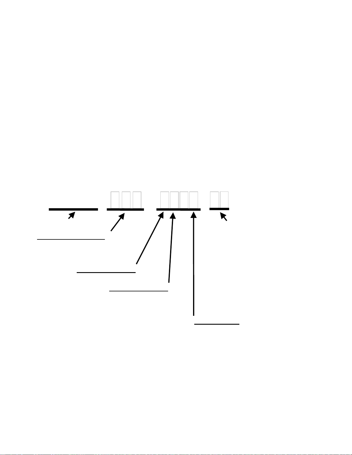
Drive Model Numbers
The Quattro DC drive is currently available
with three different output currents and a
variety of options.
The enclosure options consist of a customer
I/O panel and a side Dynamic Braking Resistor
box. The Dynamic Braking Resistor box is an
optional box that is attached to the right hand
side of the cabinet. It is used to hold the
dynamic braking resistors. The customer I/O
panel is an optional larger width cabinet that
allows for customer interfacing within the
supplied cabinet. See Dimensions / Weights
on page 104.
QDC
1 0
- -
The next option consists of shipping, either
domestically or internationally. Due to
international standards, the shipping crate
must be heat-treated.
The final option section determines the type of
motor contactor and Magnetek Operator. The
Magnetek Operator is not required to start
running, but allows for easy access to
parameters, overspeed test, and auto tuning.
drive
output current rating
125 = 125A output current
200 = 200A output current
250 = 250A out
ut current
software program
enclosure options
1 = no customer I/O panel, no side DBR box
2 = no customer I/O panel, side DBR box
3 = customer I/O panel, no side DBR box
4 = customer I/O panel, side DBR box
options
00 = No operator, ABB type
01 = Operator, ABB type
02 = No Magnetek Operator,
03 = Operator, Dual DC
shipping type
1 = domestic
2 = international
Contactor
Contactor
Dual DC Contactor
Contactor
11

Quattro DC Startup Guide
Quattro startup guide
Initial Inspection
Unpacking
1. When unpacking, check drive for any
shipping damage.
2. The 200A and 250A versions of the
Quattro arrive in separate shipping
containers, which require connection in the
field. Prior to connecting enclosures,
check serial numbers on each cabinet
section to insure mating compatible units.
Proper mating of enclosures and wiring
between is important. Refer to the reconnection instructions on page 98.
3. Review the technical manual, shipped with
the drive.
4. Verify the proper drive model numbers and
voltage ratings as specified on the
purchase order.
5. Location of the Quattro is important for
proper operation of the drive and normal
life expectancy.
Installation
The installation should comply with the
following:
− DO NOT mount in direct sunlight, rain or
extreme (condensing) humidity.
− DO NOT mount where corrosive gases or
liquids are present.
− AVOID exposure to vibration, airborne dust
or metallic particles.
− DO NOT allow the ambient temperature
around the control to exceed the ambient
temperature listed in the specification.
Observe the following precautions:
1. Wiring guide lines
For Logic Input and Output I/O
connections, use quality, multiconductor cable or discrete stranded
wire only.
For Encoder and Analog I/O
connections, use quality, multiconductor braided shield cable*.
For Communication I/O connections,
use quality, multi-conductor braided
shield* cable or twisted pair wire.
*Cable shields to be terminated with a 180/360
degree metal cable clamp attached to Control
Tray panel flange. Refer to the EMC
Compliance on page 97.
2. Never connect main AC power to the
output terminals
3. Never allow wire leads to contact metal
surfaces. Short circuit may result.
4. SIZE OF WIRE MUST BE SUITABLE FOR
CLASS I CIRCUITS.
5. Motor lead length should not exceed 20m
(60 ft). If lead length must exceed this
distance, contact Magnetek for proper
installation procedures.
6. The following are required to be contained
in individual conduit runs: 3-phase
incoming power, control power, DC
armature wires, and DC shunt field.
7. Use UL/CSA certified connectors sized for
the selected wire gauge. Install
connectors using the crimping tools
specified by the connector manufacturer.
8. Control wire lead length should not exceed
20m (60 ft). Signal leads and feedback
leads should be run in separate conduits
from power and motor wiring.
9. Verify that the input voltage matches the
drive’s rating.
10. Verify that the motor is wired for the
application voltage and amperage.
11. Tighten all of the three-phase power and
ground connections. See Table 1 for
torque specs.
Wire References Torque Specs
Power Terminals 56.6 N-m (500 in-lbs)
Plastic Cover Screws 0.23-0.28 N-m (2-2.5
in-lbs)
Ground Terminals 31.0 N-m (275 in-lbs)
Table 1: Input Power Torque Specs
12. Check that all control and signal
terminations are also tight.
CAUTION: TO PREVENT DAMAGE TO THE
DRIVE. THE FOLLOWING CHECKS MUST
BE PERFORMED BEFORE APPLYING THE
INPUT POWER.
− During shipping, connections may loosen;
inspect all equipment for signs of damage,
loose connections, or other defects.
− Ensure the three-phase line voltage is
within ±10% of the nominal input voltage.
Also verify the frequency (50 or 60 Hz) is
correct for the elevator control system.
− Remove all shipping devices.
− Ensure all electrical connections are
secure.
− Ensure all transformers are connected for
proper voltage.
12

− Open F1 and F2 and ensure control power
brought into fuse F1 and F2 is 230VAC!
IMPORTANT: Double-check all the power
wires and motor wires to make sure that they
are securely tightened down to their respective
lugs (loose wire connections may cause
problems at any time).
Grounding considerations
1. Encoder
a. Encoder isolation
− The encoder must be electrically
isolated from the motor frame and
the motor shaft.
b. Encoder cable
− The cable type should PVC braided
shielded type with three 22ga
twisted pairs. A and A/, B and B/,
common and V should be the
signals paired together.
− The encoder shield is not to be
connected at the encoder end. On
the drive side of the cable a portion
of PVC material 1inch [25mm]
should be removed approximately
12inches [300mm] from the
connection to the customer
interface PCB (A6) to expose the
shield material. This point is
required to be secured under a
clamp located under the control
tray. Do not connect the shield to
any other point. Refer to the EMC
Compliance on page 97.
2. Motor frame
a. The motor frame is required to be
grounded. The bond wire should be
returned to the common ground point
located in the Quattro enclosure (PE).
3. Three phase power
a. The three phase wires must be run
with a ground wire. This ground wire,
which is connected back to the utility
ground, is required to be connected to
the Quattro ground (PE).
4. Control power, 230VAC
a. The neutral side of the control power is
required to be grounded at the Quattro
ground (PE).
Initial adjustments after power up
Encoder Set-up
Electrical interference and mechanical speed
modulations are common problems that can
result in improper speed feedback getting to
the drive. To help avoid these common
Quattro DC Startup Guide
problems, the following electrical and
mechanical considerations are suggested.
IMPORTANT
Proper encoder speed feedback is essential
for a drive to provide proper motor control.
Electrical Requirements:
− Insulate both the encoder case and shaft
from the motor
− Incremental encoder type
− Use twisted pair cable with shield tied to
chassis ground at drive end
− Use limited slew rate differential line
drivers
− Do not allow capacitors from internal
encoder electronics to case
− Do not exceed the operating specification
of the encoder/drive (300Khz @ rated
motor speed maximum)
− Use the proper encoder supply voltage
and use the highest possible voltage
available. The Quattro DC provides both
5VDC and 12VDC. Magnetek
recommends using the 12VDC for the
encoder supply.
Mechanical Considerations:
− Use direct motor mounting without
couplings
− Use hub or hollow shaft encoder with
concentric motor stub shaft
− If possible, use a mechanical protective
cover for exposed encoders
− It is not advisable to use friction wheels
Enter / Verify the encoder pulses entered in
the ENCODER PULSES (A1) parameter
matches the encoder’s nameplate.
Motor Parameter Set-up
Enter / Verify the following from the motor’s
nameplate:
1. Motor Current (RATED MTR CURRENT
(A6))
2. Motor Voltage (RATED ARM VOLTS (A6))
3. Motor field amps, forcing (FULL FLD
AMPS (A6))
4. Motor field amps, running (WEAK FLD
AMPS (A6))
5. Motor field amps, standing (STNDBY
FIELD (A6))
Hoist way Parameter Set-up
Enter / Verify the hoist way parameters:
1. CONTRACT CAR SPD (A1) parameter
programs the elevator contract speed in
ft/min or m/s.
13

Quattro DC Startup Guide
2. CONTRACT MTR SPD (A1) parameter
programs the motor speed at elevator
contract speed in RPM.
Line voltage setup
Enter / Verify the line voltage parameter:
1. INPUT L-L VOLTS (A5) parameter
programs the line voltage level
Auto tune Procedure
Refer to page 95 on how to implement Auto
tune if desired. Auto tune will automatically
measure the motor’s armature inductance,
armature resistance including cable resistance,
field resistance, and field time constant. Auto
tune will also calculate the armature resistance
voltage drop at motor rated current and the
armature and field regulation gains.
(C1, C2, C3, C4) configuration setup
It will be required to adjust the configuration
menus to operate the Quattro as the elevator
manufacturer has specified to interact with the
car controller. Magnetek does not supply this
data.
Low speed inspection mode
Run the drive in low speed inspection mode
and…
1. Verify encoder polarity, the motor rotation
should match the encoder phasing. The
equivalent of swapping A and /A can be
done with the ENCODER CONNECT (C1)
parameter.
2. Verify proper hoist way direction. This can
be reversed with the MOTOR ROTATION
(C1) parameter.
If using an external speed regulator, which
produces an analog torque command to
Quattro (SPEED REG TYPE (C1) =
external reg and EXT TORQ CMD SRC
(C1) = analog input), it is imperative that
the encoder polarity matches the armature
voltage. To verify polarity, insert a torque
command into the analog input. Check
ENCODER SPD (D2) against ARMATURE
VOLTAGE (D2). Verify they are the same
polarity. If not, swap A and /A or change
the ENCODER CONNECT (C1) parameter.
WARNING
Verify that the Safety Chain / Emergency Stop
works.
14
Interconnections
–
A
Z
A
A
A
A
A
A
A
O
O
A
A02AC
A
A
A
A
A
A
A
A
A
A
-
-
9JCC1-4
Contact
Cfirm
5*
CTR PWR Sense
*Located on A9TB1
To/ From
Encoder, Use
+5 or +12 Volt
supply power
From Customer
nalog Outputs
9JCC1-2
6*
9JCC1-1
TB1
11
1
2
3
4
5
6
7
8
9
10
43
44
45
46
34
35
36
37
38
39
40
41
42
15
16
18
19
17
TB2
7
14
+24 VISO
LI1
LI2
LI3
LI4
LI5
LI6
LI7
LI8
LI9
LIB
C_24VISO
C_24VISO
C_24VISO
+24 VISO
/A
/B
B
/Z
C_ISO
+5VISO
+12VISO
IN1+
IN1-
IN2+
IN2-
COM
BB_1
BB_2
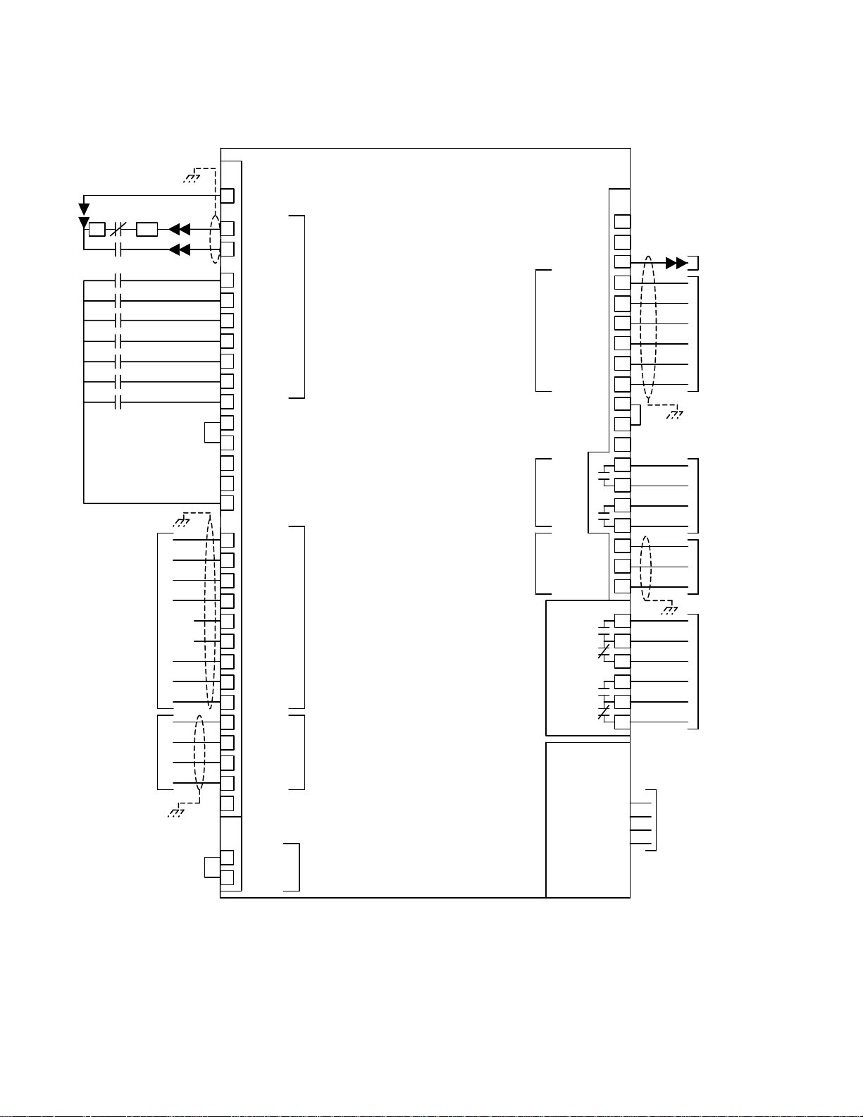
QUATTRO SIGNAL
CONNECTIONS
Logic
Inputs
To / From
Encoder,
Use +5 or +12
volt Supply Power
s Required.
+/- 10V
nalog Inputs
Base Enable
Jumper
A6
Open Collector
Outputs, 24 VDC,
15mA Max
Solid State
Relay Outputs,
50V AC/DC
Max 150 mA
nalog Outputs,
+/- 10 VDC,
+/- 4mA
Relays,
230VAC 1A or
30VDC 2A
Quattro DC Interconnections
TB1
LO1
LO2
LO3
LO4
LO5
LO6
LO7
LOC
01
-RTS
+CTS
TXRX+
TXRX
RX
RX+
47
48
25
26
27
28
29
30
31
32
33
45
21
22
23
24
12
13
14
1
3
5
8
10
12
1
6
2
7
3
8
4
9
5
9JCC1-3
To contactor
pickup Relay K on
9
Open collector
Outputs, 30VDC,
150mA max
Solid State relay
Outputs,
50V AC/DC
Max 150mA Max
nalog Outputs,
+/- 10 VDC,
+/- 4mA
Relays, 230 VAC
1A or 30VDC 2A
RS422
Customer
Serial Link
+24VISO
+24VISO
C_24VIS
C_24VIS
SSR1
SSR2
TB2
Relay 1
Relay 2
JC4
+5V_SA
COM_SA
Figure 1: Interconnection Diagram
15

Quattro DC Interconnections
)
2
A
)
E
E
A
EMEME
* Note 1
* Note 1
H(X) H(1)
Provided for
the Primary
side of the
230V control
power
transformer
GND
L(1) L(2) L(3
To Quattro Drive
Internal Control
Power
F1
F2
TB1
24
SWout (+)
Motor Fi eld Contr ol
DCout (-)
Safety Chai n
3
Control Power
230VAC hi 230VAC lo
* Note 1
Motor Shunt Field
M
TB1K1 K1 TB1 ME TB1 TB1
4
3
Located on A9
Not es:
(F1)(F2
* Note 1
1. * indi cates components
not suppli ed by Magnetek
2 1
Safety Chain
* Note 1
(21) (22) (13) (14) (43) (44)
Motor Contactor Auxiliaries
ME
(4) (3)
K1
Part of A9
M
(5) (6)
M
(2) (1)
Figure 2: Quattro DC Power Connections
DBR
DBR
1-4
5-8
(A1)
* Note 1
Hoi st Motor
(A2)
Encoder to
6TB1
16
Quattro DC Interconnections
A
A
A
A
A
Encoder Connections
The Quattro DC has connections for an
incremental two-channel quadrature encoder.
The Quattro DC requires the use of an encoder
coupled to the motor shaft. The encoder power
can be either a +5VDC or +12VDC.
The encoder pulses per revolution must be
entered in the ENCODER PULSES parameter
in the A1 submenu.
Figure 3 shows the encoder connection
terminals for non-single ended applications.
TB1
34
35
36
37
38
/A
/B
B
/Z
39
40
41
42
Z
C_ISO
+5V_ISO
+12V_ISO
Figure 3: Encoder Connections
Below shows the connection for the encoder
option card, if they are configured to be single
ended. This configuration is not recommended,
since, the Quattro DC encoder noise immunity
circuitry is not in effect.
TB1
34
35
/A
36
37
38
39
40
/B
B
/Z
Z
C_ISO
41
42
+5V_ISO
+12V_ISO
Figure 4: Encoder Connections (Single-
Ended)
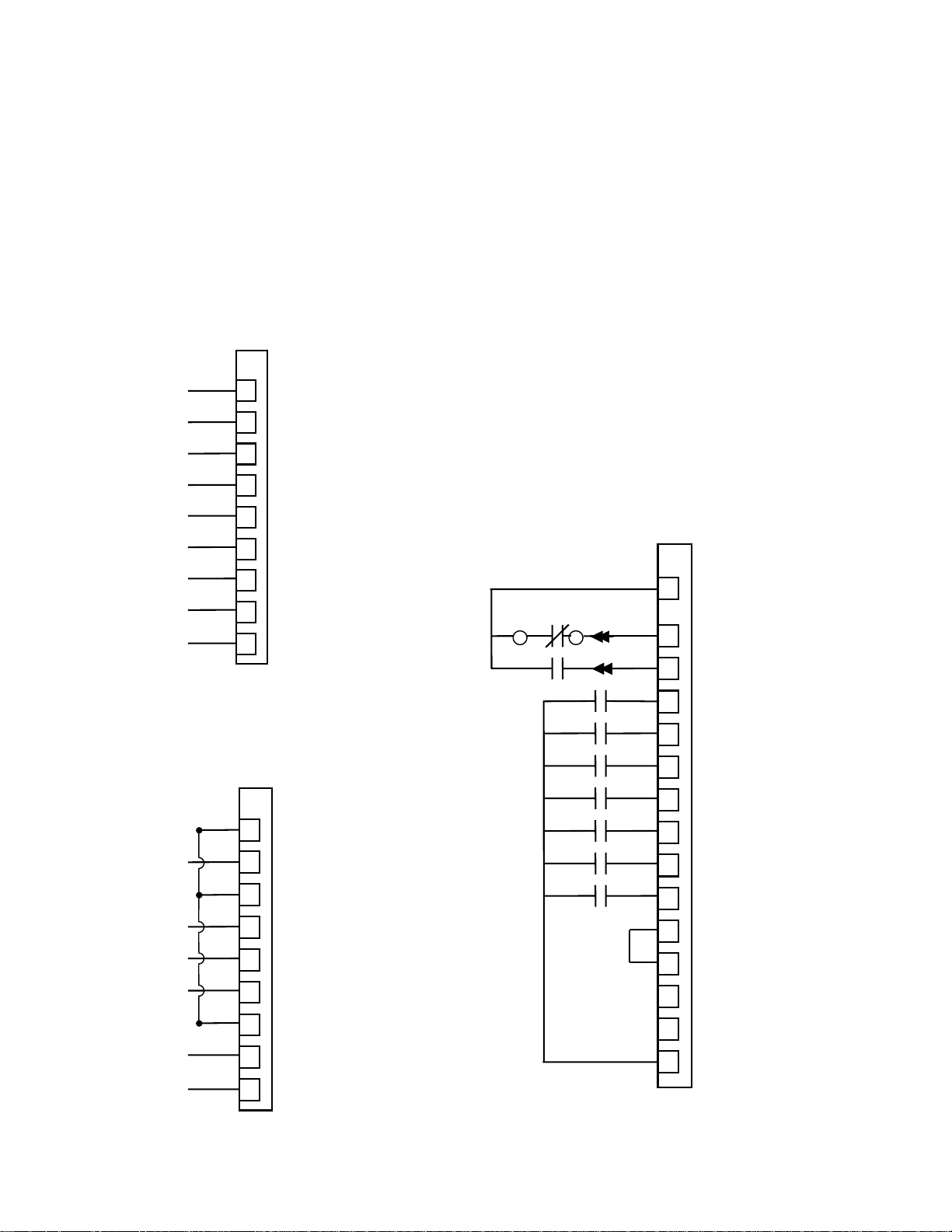
Logic Inputs
The Quattro DC’s nine programmable logic
inputs are opto-isolated.
For more information
on programming logic inputs, see Logic Inputs
C2 submenu on page 61.
The inputs become
“true” by closing contacts or switches between
the logic input terminal and voltage source
common (or voltage source). The inputs are
sourcing inputs – nominally sitting at common
and when the contacts or switches are closed,
turning “true” at 24VDC. The voltage supply for
the logic inputs is 24VDC.
IMPORTANT
Internal 24VDC power supply has a capacity of
100 mA
Note: Logic input 1 and 2 are reserved and prewired for CONTACT CFIRM and CTR PWR
SENSE respectively.
The choices for the voltage source common (or
voltage source) depend on if the user is using
an external voltage supply or using the internal
voltage supply. See Figure 5 for internal supply
example and Figure 6 for external supply
example.
Contact
Cfirm
9TB1
5
CTR PWR Sense
6
9JCC1-2
9JCC1-1
TB1
11
+24VDC isolated
1
logic input 1
2
logic input 2
3
logic input 3
4
logic input 4
5
logic input 5
6
logic input 6
7
logic input 7
8
logic input 8
9
logic input 9
10
logic input common
43
+24VDC iso. common
44
+24VDC iso. common
45
+24VDC iso. common
46
+24VDC isolated
Figure 5: Logic Input Diagram (Internal
Supply)
17

Quattro DC Interconnections
A
A
A
+
Contact
Cfirm
9TB1
5
CTR PWR Sense
9JCC1-2
6
9JCC1-1
+24V external
supply
Figure 6: Logic Inputs (External Supply)
Analog Inputs
The Quattro DC has two non-programmable
differential analog input channels.
• Analog input channel 1 is reserved for the
speed command (if used).
• Analog input channel 2 is reserved for the
pre-torque command (if used) or torque
command source (if used).
The analog input channels are bipolar and have
a voltage range of ±10VDC.
Available with the analog channels is multiplier
gain parameters (SPD COMMAND MULT and
EXT TORQUE MULT) and bias parameters
(SPD COMMAND BIAS and EXT TORQUE
BIAS). These parameters are used to scale the
user’s analog command to the proper range for
the drive software. The formula below shows
the scaling effects of these two parameters.
analog
⎛
⎜
channel
⎜
input
⎜
voltage
⎝
−
⎞
⎟
⎟
⎟
⎠
TB1
+24VDC isolated
11
1
logic input 1
2
logic input 2
3
logic input 3
4
logic input 4
5
logic input 5
6
logic input 6
7
logic input 7
8
logic input 8
9
logic input 9
10
logic input common
43
C_24VISO
44
C24VISO
45
C24VISO
46
+24VDC isolated
MULTBIAS
=×
signal
drive
software
uses
For more on the multiplier gain or bias
parameters, see Drive A1 submenu on page 30.
The scaling of the analog input signals, with
BIAS set to 0.00 and MULT set to 1.0 follows:
• Speed Command
+10VDC = positive contract speed
-10VDC = negative contract speed
• Pre Torque Command
+10VDC = positive rated pre-torque of motor
-10VDC =
negative rated pre-torque of motor
• Torque Command
+10VDC = positive rated torque of motor
-10VDC =
negative rated torque of motor
NOTE: The drive cannot recognize voltages
outside of the
±10VDC on its analog input
channels.
The Quattro DC provides common mode noise
rejection with the differential analog inputs. The
connection of these two differential inputs is
shown in Figure 7.
Speed Cmd
±10V
PreTorque
Cmd, ±10V
or Torque
Command, ±10V
TB1
analog input 1+
15
analog input 1-
16
analog input common
17
analog input 2+
18
analog input 2-
19
Figure 7: Analog Inputs (Differential)
Figure 8 shows the connection for the analog
inputs if they are configured for single-ended
connection. In this configuration, the Quattro
DC noise immunity circuitry is not in effect.
Note: For prevention of ground noise
interference, a twisted shielded pair must be run
to the source and not connected at the board.
Speed Cmd
±10V
PreTorque
Cmd, ±10V
or Torque
Command, ±10V
TB1
analog input 1+
15
analog input 1-
16
analog input common
17
analog input 2+
18
analog input 2-
19
Figure 8: Analog Inputs (Single Ended)
18

Quattro DC Interconnections
A
Logic Outputs
The Quattro DC’s seven programmable logic
outputs are opto-isolated, open collector. The
outputs are normally open and can withstand an
applied maximum voltage of 30VDC. When the
outputs become “true”, the output closes and is
capable of sinking up to 150mA between the
logic output terminal and the logic output
common (TB1-32). Figure 9: Logic Outputs
shows the logic output terminals.
Note: Logic Output 1 is prewired for CLOSE
CONTACT.
logic output common
+24V iso. common
+24V iso. common
+24V iso.
+24V iso.
logic output 1
logic output 2
logic output 3
logic output 4
logic output 5
logic output 6
logic output 7
TB1
47
48
25
26
27
28
29
30
31
32
33
45
9JCC1-3
Figure 9: Logic Outputs
For more information on programming the logic
outputs, see Logic Outputs C3 submenu on
page 63.
Relay Outputs
The Quattro DC’s two programmable relay logic
outputs are Form-C relays. The have both
normally open and normally closed contacts.
The specifications for each relay are as follows:
Relay 1
• 2A at 30VDC or 1A at 230VAC
Relay 2
• 2A at 30VDC or 1A at 230VAC
Figure 10: Relay Outputs shows the logic output
terminals.
TB2
1
relay 1
relay 2
3
5
8
10
12
Figure 10: Relay Outputs
For more information on programming the relay
outputs, see Logic Outputs C3 submenu on
page 63.
Solid State Relay Outputs
The Quattro DC has two programmable solidstate relays. They have a 30 VDC max with
150mA load capability.
Figure 11: Solid State Relay Outputs shows the
relay output connections.
TB1
solid state relay 1
solid state relay 2
21
22
23
24
Figure 11: Solid State Relay Outputs
For more information on programming the solidstate relays, see Logic Outputs C3 submenu on
page 63.
19

Quattro DC Interconnections
Analog Outputs
The Quattro DC has two programmable
differential analog output channels. The two
analog output channels were designed for
diagnostic help.
programming the analog output channels, see
Analog Outputs C4 submenu on page 65.
The analog output channels are bipolar and
have a voltage range of
draw of +/- 4mA.
Available with the analog channels is multiplier
gain parameters (ANA 1 OUT GAIN and ANA 2
OUT GAIN) and a bias or offset parameters
(ANA 1 OUT OFFSET and ANA 2 OUT
OFFSET). These parameters are used to scale
the user’s analog outputs to the proper range
for the drive software. The formula below
shows the scaling effects of these two
parameters.
signal
⎛
⎜
drive
⎜
software
⎜
creates
⎝
−
For more information on
±10VDC and current
=×
analog
channel
output
voltage
⎞
⎟
GAINOFFSET
⎟
⎟
⎠
For more on the gain or offset parameters, see
section Drive A1 submenu on page 30.
The connection of these two outputs is shown in
Figure 12: Analog Outputs.
TB1
analog output 1
analog output 2
analog output com
12
13
14
Figure 12: Analog Outputs
For more information on programming the
Analog Outputs, see Analog Outputs C4
submenu on page 65.
20

Quattro DC Drive Sequencing
Drive Sequencing
NORMAL operating sequence
1. Motor field current is at Stand-By during
drive idle. The No Faults relay is active.
Full-Field and Run command signals are
OFF. Motor contactor Safety circuits may
be open or closed. The DC bus will
remain charged with regulated voltage as
long as the drive is providing motor field
current.
2. A Field Enable Command, programmable
by FLD ENA SRC (C1), is sent to the
drive. If the DC bus is not pre-charged, a
pre-charge cycle will be completed before
motor field current is restored. See
Quattro Pre-Charge on page 22 for timing
information of the Pre-Charge circuit.
Motor field current will go to the Full-Field
value in preparation to produce motor
torque.
Field Enable
Motor Field
Stndy Fld
FLUX CFRM
(logic output)
Drive Enable
Run
3. Pre-Torque command value is sent to the
drive. It must be available before a run
command is given. If the Pre-Torque
Latch is used, see Pre-Torque Latch (C1),
it can be placed inactive depending on the
settings of Pre-Torque Latch Clk (C1). If
latching is not used, it must remain active
until the SPD REG RLS output is active.
Safety circuit relays are closed making
power available to the contactor coil
circuit.
Pre-Torque
Run
Safety Chain
CONTACT
CFRM (input)
SPD REG RLS
(output)
Full Fld
Field Enable (input)
Stand-by On
Pre-charge
Pre-charge Cnfrm
Boost On
Flux Confirm
Drive Enable
Run Command
(input)
(input)
LATCH
Pick Contactor
Speed Reg Release
No Faults
Contact Cfirm
4. Once the regulators are released, motor
current starts at pre-torque amperes. The
velocity regulator starts at zero speed. (All
conditions of 3. must be present and motor
field current must be greater that the
sensing threshold before the drive will Start.
This is noted by the output Flux Confirm
(programmable by Flux Cnfrm Level (A6)).
5. Drive activates elevator Brake relays, if
programmed to do so (or the car controller
does it externally).
6. Drive follows the external or internal
velocity profile via the programmed
accel/decel rate as programmed during the
remainder of the elevator run cycle.
7. When at the next landing...the Drive (or
car controller) de-activates elevator Brake.
8. After the Brake has set, the Run command
is removed causing...
9. Reference speed to be clamped to zero.
10. Motor torque ramps down to zero, then the
Motor contactor is opened.
Brake Relay
Run
SPD REG RLS (logic output)
Torque
Motor Contactor
11. While idle, motor field current reference will
drop to Stand-By, after the Full-Field timer
expires. Safety circuit relays may (or may
not) open to remove contactor-actuating
power.
12. A DSPR time-out may occur while field
current is at stand-by. In that case motor
field current goes to zero and the AC main
power contactor to the drive is opened. A
pre-charge cycle and power on recovery
will occur on the next command to reestablish motor field current.
21
Boost On Confirm
Field
Control
On
Speed Ref
Release
Brake Release

Quattro DC Drive Sequencing
ABNORMAL Operation Sequence
1. If a Drive or Drive Sequence Fault occurs
the Drive will immediately open the motor
contactor, de-energize the Brake Pick,
Brake Hold, and Drive OK Relays if so
programmed. May be caused by:
a. “Fatal Error” drive Faults including loss
of serial communications
b. Opening of the contactor power Safety
circuit while the contactor is pulled in
c. Loss of correct motor contactor or
Brake Relay feedback.
2. If an Alarm occurs, the drive will signal an
Alarm but continue to run. May be caused
by:
a. Drive Alarms including motor overload,
drive over temp warning
b. Loss of correct feedback from Brake
Hold relay or Brake Switches
c. Open motor thermostat circuit
d. Speed command is held at zero due to
conflict with the analog speed
command polarity and the run up/ run
down logic
e. Encoder Fault (C1) set to disabled
f. The drive is or was being limited by
the motor torque limit setting (Hit
Torque Limit)
g. Speed feedback is failing to properly
track the speed reference (Speed Dev)
h. DC bus voltage drops below user
specified percent of the input line to
line voltage
Quattro Pre-Charge
When power is first applied to the Quattro
drive, or after it has shut itself down via a
DSPR time-out, the internal DC bus must be
pre-charged before operation can resume.
The following sequence will occur:
1. Power is applied to the Quattro drive
a. Control power may be applied before or
after 3-phase main power
b. Some OEM drive versions may have a
built-in control transformer
c. Drive controls should become active
but no contactors should operate
2. Quattro drive receives command to
‘energize’
a. This command may be from serial link
software or hardware logic command to
deliver motor field current in
preparation to start.
b. AC input voltage from mains is
measured and verified to be adequate
according to the setting of the VACinput adjustment parameter.
c. Pre-charge contactor PCM is then
pulled in. This provides resistor limited
inrush current to DC bus capacitors
from AC mains and separate rectifier.
3. DC bus is Pre-Charged
a. With pre-charge contactor PCM closed,
separate resistor and rectifier circuits
limit capacitor charging inrush current.
b. Bus voltage is monitored during pre-
charge to verify proper voltage build-up.
(See 6.a. below)
c. Target bus voltage is nominal input
VAC (INPUT L-L VOLTS (A5)) X √2.
4. Mains contactor is closed
a. As measured DC bus voltage nears
target value main utility power contactor
UTM closes.
b. Aux contact feedback from UTM
indicates to controls that main utility
contactor is closed.
c. Then Pre-charge contactor PCM is
opened. (See 6.b. below)
5. Boost converter is turned ON.
a. DC bus voltage is boosted to a higher
level as programmed by the Boost
Level parameter setting in order to
achieve near unity power factor and low
harmonic content of the Quattro drive.
b. Motor field controls also turn ON to
begin regulating motor field current
and/or operate main motor armature
circuits.
c. The boost converter will remain ON as
long as any field or armature current is
being provided to the motor. (See 6.c.
below) Time-out of the DSPR (Drive
Stand-by Power Reduction) feature or
other command may turn the Boost
converter OFF when drive is idle
although standby field will still be
present. In that case as new precharge cycle must occur before drive
re-start.
6. Problem prevention
a. If DC bus voltage does not rise at the
expected rate to the expected voltage
level during pre-charge a “Charge
Fault” is declared.
b. UTM and PCM are interlocked with aux
contacts such that UTM cannot be
picked unless PCM is already closed.
Once picked, an aux contact of UTM
seals the same circuit allowing PCM to
be dropped with UTM remaining ON.
c. In the event of a major drive Fault, UTM
will be opened to disconnect utility lines
from main power devices of Quattro.
22

Quattro DC Drive Operation and Feature Overview
Drive Operation and Feature Overview
The Quattro DC drive is a velocity and torque
regulated motor drive designed specifically for
operating elevators. Many of the features
described below can be selectively
programmed to customize an individual
application.
Analog Velocity Follower
The elevator car controller provides an analog
velocity reference to the drive at A6TB1-15
and A6TB1-16. The signal may be bi-polar +/10 VDC to indicate speed and travel direction,
or a positive only unipolar signal with the
direction of travel selected by logic commands.
In most cases the signal profile will be adjusted
by the car controller for precise landing
positioning. The velocity reference passes
directly to the closed loop velocity controller,
except for an internal rate limiter to buffer any
unexpected electrical noise. Start and Stop
commands are via 24VDC logic inputs.
Calibration of the analog velocity reference
signal may be adjusted with separate gain and
offset parameters. To set the Analog Velocity
Follower, the user must set SPD COMMAND
SRC (C1) to Analog Input.
Preset Speed & Profile Generator
An alternate method of speed control is that
the elevator car controller provides 24VDC
logic input commands to select one of 15 predetermined running speeds. The drive
generates a smooth S-Curve acceleration
profile to transition between speed selections.
Either of three separately adjustable ramp
times may be selected. The direction of travel
may be determined by either a Run command
with an Up/Down command signal or by
separate Run-Up / Run-Down logic
commands. To set the Analog Velocity
Follower, the user must set SPD COMMAND
SRC (C1) to Multi-Step, then adjusting MultiStep Speed Commands in the Multi-Step
Submenu A3.
Serial Link Follower
The elevator car controller provides the
equivalent of an analog reference command
over a digital serial link. The drive returns
operating status conditions and messages.
Primary run command are 24VDC logic for
redundant safety if wanted. The speed
sensitivity of the serial velocity reference is
adjustable. Enabling the serial link follower
requires SPD COMMAND SRC (C1) to be set
to SERIAL.
Pre-Torque
When enabled, the speed error integrator will
be pre-conditioned by the supplied pre-torque
signal before starting the regulator. This will
cause motor armature current to begin at a
magnitude proportional to the pre-torque
command to prevent elevator motion or
rollback when the elevator brake is released.
The pre-torque signal will be from either an
analog (wired at A6TB1-18 and A6TB1-19) or
serial link digital source as selected by
programming PRETORQUE SOURCE (C1). If
Pre-Torque is not used, leave PRETORQUE
SOURCE (C1) at the defaulted value of none.
An EXT TORQUE BIAS (A1) and an EXT
TORQUE MULT (A1) are available to scale the
pre-torque signal. Ten volts = rated motor
current with a multiplier of 1 and a bias of zero.
Torque Feed Forward
Some car controllers may calculate an
accurate demand for motor torque as required
to accelerate the connected load as well as
hold it against gravity. The torque demand
signal can be programmed to directly drive the
torque control part of Quattro from either an
analog or serial link input. EXT TORQ CMD
SRC (C1) must be set to either analog input or
serial and SPEED REG TYPE (C1) must be
set to either pi speed reg, elev spd reg, or
external reg. The connections for an analog
external torque command source are A6TB118 and A6TB1-19. With an accurate torque
compensating signal, the gain of the PI
regulator can be reduced, to better ignore and
not amplify mechanical vibrations of the hoist
way. Separate adjustments are provided for
torque signal gain and offset. An EXT
TORQUE BIAS (A1) and an EXT TORQUE
MULT (A1) are available to scale the torque
signal. Ten volts = rated motor current with a
multiplier of 1 and a bias of zero.
Torque/Current Ramp-Down
When the drive is told to cease operation by
removal of the Run logic command, (and after
Brake Drop time if that function is engaged)
the armature current reference ramps down to
zero at a constant rate. This allows the
mechanical Brake to gently assume elevator
holding torque, reducing the tendency to
‘thump’ the brake. When armature current
ramp-down is complete, the contactor will be
opened. In the event that the contactor opens
unexpectedly, as reported by the feedback
contact or in the event of a severe drive fault,
23

Quattro DC Drive Operation and Feature Overview
there will be no timed delay for current rampdown. This time may be adjusted by the
function RAMPED STOP TIME (A1).
Motor Field Current Control and Field weakening
DC elevator motors have a separately excited
shunt field. Adjustments include Stand-By
Current, Full-Field Current and Weak-Field
Current, all programmed in amperes, and a
Flux Confirm Level, programmed as a % of
Full-Field. With no active Full-Field or drive
Run command motor field current would
normally be at Stand-By amps. An active
command to provide Full Field causes field
current to increase to the Full Field setting.
When Field current is greater than the FullField threshold setting (and there are no other
faults) the DC motor contactor will be enabled
to pull in when told to do so by an active drive
Run command. When the motor contactor is
acknowledged as being closed, the motor
armature current regulator is released to follow
the commanded torque reference current
signal. Motor field current will remain at the
Full-Field value as long as the per unit (pu)
reference or measured speed (whichever is
greater) is less than the pu ratio of WF/FF
amps. Above that speed motor field current
will automatically follow the constant CEMF
profile of WF/FF X 1/spd, where speed is again
the greater active value of reference or
measured speed. When motor speed reduces
from high speed, motor field current
automatically increases according to the
constant CEMF calculated profile. However,
field current will not increase to be more than
the Full field ampere setting.
DSPR
While the drive is idle with Stand-By Current
being applied to the motor field, a second timer
for Drive Stand-by Power Reduction (DSPR)
will be running. When/If the DPSR timer
times-out, motor field current will turn
completely Off and the main 3-phase power to
the drive will be removed. This helps save
electrical energy during long periods of nonuse. Recovery of this condition will be
automatic upon the receipt of the next “FullField” or “Run” command. At that time,
recovery from a DSPR power OFF condition
may take several seconds. DSPR TIME can
be set in the Drive A1 Submenu.
Over-Speed Test
A reference speed multiplier is provided to help
testing of the elevator governor over-speed
trip. This feature will automatically return to
normal at the completion of each elevator run.
However, to ensure that the drive Over-Speed
Trip does not interfere with the governor test,
one must temporarily raise the value set for the
Drive Over-Speed Trip point to a value higher
than that of the governor.
Fault & Alarm Reset
An external Fault Reset command signal from
the car controller may be applied to a logic
input or from a serial command link. Or, an
automatic Fault Reset will occur 5 seconds
after a drive fault occurs, when enabled to do
so. Either method may be used to enable the
car controller to quickly recover from a resettable fault. One Fault will be subtracted
from a fault count accumulation every 20
minutes. The maximum number of AutoResets that can be accumulated is 5. The
Auto-Reset function will then require a power
Off/On cycle in order to recover. Faults &
Alarms may also be cleared by use of the
Magnetek Operator.
Electronic Motor Over-Load
An electronic motor over-load function is
provided to take the place of heater type power
components. Motor armature current is
continuously monitored and the heating effect
is calculated over time. A motor overload trip
will not automatically stop the drive, but is an
important alarm signal to elevator car controller
to help prevent equipment damage.
Armature Voltage Feedback
This is a temporary ‘construction’ or trial mode
for proving out direction orientation of the
motor and operation of the encoder. Motor
speed regulation is controlled by armature
voltage feedback with IR compensation.
Precise speed regulation is not possible.
Operation above base speed of the motor is
not possible since the field weakening is
inhibited. However, it is still possible to
monitor the feedback from the encoder
although it will not used for speed regulation.
Successful operation in this mode may require
reduced gain settings. This is selectable by
setting SPD REG TYPE (C1) to CEMF REG.
24

Quattro DC Drive Operation and Feature Overview
Status Indicator Lights
Five status indicator lamps are provided on the
front panel of the drive.
READY – (GRN) Power is applied to the drive,
there are no drive Faults and drive is
ready to Run when requested. The Run
light will blink slowly when it is in DSPR
(Drive Standby Power Reduction) Mode
or not boosting, but three-phase power is
applied.
RUN – (GRN) Indicates that the motor
contactor is closed and the drive is
following applied references operating to
control torque and speed
PROGRAM INVALID – (RED) There is no
valid program loaded.
FAULT – (Red) A drive Fault exists that is
preventing the drive from operating
CURRENT LIMIT – (YEL) Motor current is
being limited
READY
RUN
PROGRAM INVALID
FAULT
CURRENT LIMIT
MONITOR / Adjust / Set-up Parameters:
The values of all adjustments and set up
parameters are stored locally in non-volatile
drive memory. Monitoring of live data status
and modification of parameter values can be
accomplished by sequences over the serial
link or the Magnetek Operator. They can both
be attached at the same time to modify
parameters or monitor drive operation.
Detailed descriptions of all adjustments are
located in later sections of this manual.
25

Quattro DC Parameters
A
Parameters
Parameter Introduction
This section describes the parameter menu
structure of the Magnetek Operator, how to
navigate this menu structure, and a detailed
description of each parameter.
Parameters are grouped under six major
menus:
• ADJUST A0
• CONFIGURE C0
• UTILITY U0
• FAULTS F0
• DISPLAY 1 D0
• DISPLAY 2 D0
When the SUB-MENU LED is off, the currently
selected menu is shown on the top line of the
Digital Operator display and the currently
selected sub-menu is shown on the bottom line
of the Digital Operator display.
Display 1 D0 Adjust A0 Configure C0 Utility U0 Faults F0 Display 2 D0
DISPLAY 1 D0
D1 ELEVATOR DAT
RUN/FAULT
SUB MENU
DATA ENT
Menus
Each menu has a number of sub-menus.
Following is a listing of the menus:
• ADJUST A0
• CONFIGURE C0
• UTILITY U0
• FAULTS F0
• DISPLAY 1 D0
• DISPLAY 2 D0
→ Elevator
Data D1
→ MS Power
Data D2
→ LS Power
Data D3
→ Drive A1
→ S-Curves A2
→ MultiStep Ref
A3
→ Motor side
Power
Convert A4
→ Line side
Power
Convert A5
→ Motor
Params A6
→ User
Switches C1
→ Logic Inputs
C2
→ Logic
Outputs C3
→ Analog
Outputs C4
→ Password
U1
→ Hidden
Items U2
→ Units U3
→ Ovrspeed
Test U4
→ Restore
Dflts U5
→ MS Drive
Info U6
→ LS Drive
Info U7
→ Hex Monitor
→ Active
Faults F1
→ Fault
History F2
→ Elevator
Data D1
→ MS Power
Data D2
→ LS Power
Data D3
U8
Menu/Sub-Menu Tree
26

Quattro DC Parameters
A
y
A
Menu Navigation
The digital operator keys operate on three
levels, the menu level, the sub-menu level and
the entry level. At the menu level, they
function to navigate between menus or submenus. At the sub-menu level, they navigate
between sub-menus or menu items. At the
entry level, they are used to adjust values or
select options. Six (6) keys are used for this
navigation; they are shown below:
Left Arrow
Digital Operator Keys
How these keys operate is dependent on the
“level” (i.e. menu, sub-menu or entry level.) In
general, the “ENTER” and “ESCAPE” keys
control the level. That is the ENTER key is
used to move to a lower level and the
ESCAPE key is used to move to a higher level.
The arrow keys control movement. The up and
down arrow keys control vertical position and
the left and right arrow keys control horizontal
position.
Navigation at the Menu Level
At the menu level, the up and down arrow keys
cause the display to show the sub-menus.
The side arrow keys cause the display to
select which menu is active. When the end is
reached (either up, down, left or right),
pressing the same key will cause a wrap
around.
ADJUST A0
DRIVE A1
RUN/FAULT
SUB MENU
DATA ENT
Each menu will remember the last accessed
sub-menu. The left and right arrow keys will
navigate between these last active sub-menus.
This remembrance of last active sub-menu is
volatile and will be lost at power down.
When any sub-menu is displayed, pressing the
“ENTER” key will place the operator in the submenu level.
ENTER ke
Navigation at the Sub-menu Level
When in the sub-menu level, the SUB-MENU
LED on the digital operator is lit. At the submenu level, the positioning keys work slightly
different than they did at the menu level. The
up and down arrow keys now select separate
items in the sub-menu.
CONTRACT CAR SPD
1 0400.0 fpm
RUN/FAULT
SUB MENU
DATA ENT
At any time pressing the “ESCAPE” key will
return to the menu level. Upon exiting a submenu via the “ESCAPE” key, the last item
number is “remembered”. The next time this
sub-menu is entered, it is entered at the
“remembered” item number.
This feature can be used to obtain quick
access to two monitor values. Two menus one
labeled Display 1 D0 and one labeled Display
2 D0 have the same display items. One item
can be selected one under the Display 1 menu
and another under the Display 2 menu. The
left and right arrow keys can then be used to
move back and forth between these two
display items. Remember, that the
“remembering” of sub-menus and sub-menu
items is volatile and is lost at power-down.
Navigation at the Entry Level
When in the entry level, the DATA ENT LED
on the digital operator is lit. At the entry level,
the function of keys are redefined. The
“ESCAPE” key remains as the key used to
move back to the sub-menu level. The left and
right arrow keys are used as cursor positioning
keys and the up and down arrow keys are
used as increment and decrement keys.
CONTRACT CAR SPD
1 0400.0 fpm
RUN/FAULT
SUB MENU
DATA ENT
Hidden Parameters
There are two types of parameters: standard
and hidden. Standard parameters are
available at all times. Hidden parameters are
for more advanced functions and are available
only if activated. Activation of the hidden
parameters is accomplished by setting of a
utility parameter, HIDDEN ITEMS U2.
27

Quattro DC Parameters
Parameter Tree
Display D0 Adjust A0
→ Elevator Data D1
• Speed Command
• Speed Reference
• Speed Feedback
• Speed Error
• Pre-Torque Ref
• Ext-Torque Cmd
• Spd Reg Torq Cmd
• Tach Rate Cmd
• Aux Torque Cmd
• Est Inertia
• Rx Com Status
• Logic Outputs
• Logic Intputs
→ MS Power Data
D2
• Arm Current
• Field Current
• Arm voltage
• MS Bus Voltage
• Motor Mode
• Torque Ref
• Est Spd Fdbk
• Encoder Spd
• DS Module Temp
• LS Module Temp
• Highest Temp
• Field IGBT Temp
• Armature Cur Err
• Auto Fld Int
• Auto Fld Prop
• Auto Meas Arm L
• Auto Meas Arm R
• Auto Field Res
• Auto Field TC
→ LS Power Data D2
• LS Pwr Output
• DC Bus Voltage
• DC Bus Volts Ref
• LS Overload
• LS Input Current
• LS D Axis I
• LS Q Axis I
• LS D Axis Volts
• LS Q Axis Volts
• Input Hz
• Input Vab
• Input Vbc
• LS Module Temp
→ Drive A1
• Contract Car Spd
• Contract Mtr Spd
• Response
• Inertia
• Inner Loop Xover
• Current Limit
• Gain Reduce Mult
• Gain Chng Level
• Tach Filter BW
• Tach Rate Gain
• Spd Phase Margin
• Ramped Stop Time
• Contact Flt Time
• Brake Pick Time
• Brake Hold Time
• Overspeed Level
→ S-Curves A2
• Accel Rate 0
• Decel Rate 0
• Accel Jerk In 0
• Accel Jerk Out 0
• Decel Jerk In 0
• Decel Jerk Out 0
• Accel Rate 1
• Decel Rate 1
→ Multistep Ref A3
• Speed Command 1
• Speed Command 2
• Speed Command 3
• Speed Command 4
• Speed Command 5
→ MS Pwr Convert A4
• Arm Resistance
• Arm Inductance
• Mtr Rev Vlt Lim
• If Reg Int Gain
• If Reg Prop Gain
→ LS Pwr Convert A5
• Id Reg Prop Gain
• Id Reg Intgrl Gn
• Iq Reg Prop Gain
• Iq Reg Intgrl Gn
→ Motor A6
• Motor ID
• Rated Motor Curr
• Armature Volts
• Full Fld Amps
• Overspeed Time
• Overspeed Mult
• Encoder Pulses
• Spd Dev Lo Level
• Spd Dev Time
• Spd Dev Hi Level
• Spd Command Bias
• Spd Command Mult
• Ext Torque Bias
• Ext Torque Mult
• Zero Speed Level
• Zero Speed Time
• Up/Dwn Threshold
• Ana Out 1 Offset
• Ana Out 2 Offset
• Ana Out 1 Gain
• Accel Jerk In 1
• Accel Jerk Out 1
• Decel Jerk In 1
• Decel Jerk Out 1
• Accel Rate 2
• Decel Rate 2
• Accel Jerk In 2
• Accel Jerk Out 2
• Speed Command 6
• Speed Command 7
• Speed Command 8
• Speed Command 9
• Speed Command 10
• Auto Tune Motor
• Gain Selection
• Gain Bandwidth A
• Gain Bandwidth F
• PWM Frequency
• DC Bus Reg P Gn
• DC Bus Reg I Gn
• Input L-L Volts
• DC Bus V Boost
• Weak Fld Amps
• Stndby Field
• Flux Confirm Lev
• Ana Out 2 Gain
• Flt Reset Delay
• Flt Resets/Hour
• Up To Spd Level
• Run Delay Timer
• AB Zero Spd Level
• AB Off Delay
• Contactor DO Dly
• Trq Lim Msg Dly
• Rollback Gain
• Notch Filter Frq
• Notch Filt Depth
• Stndby Fld Time
• DSPR Time
• Full Field Time
• Decel Jerk In 2
• Decel Jerk Out 2
• Accel Rate 3
• Decel Rate 3
• Accel Jerk In 3
• Accel Jerk Out 3
• Decel Jerk In 3
• Decel Jerk Out 3
• Speed Command 11
• Speed Command 12
• Speed Command 13
• Speed Command 14
• Speed Command 15
• Fan Off Delay
• Main Fan Control
• UV Alarm Level
• UV Fault Level
• Fld Carrier Frq
• SW Bus OV Level
• Bus Vref Source
• PLL Filter Fc
• LS PWM Frequency
• Armature IR Drop
• Ovld Start Level
• Ovld Time Out
28