


 Loading...
MST/E Electric Shoe Brakes
Mondel MST/E Electric Shoe Brakes Instruction Manual
Part Number: 560022-R6
July 2006
© Copyright 2006 Magnetek Material Handling

Installation and Maintenance
Instructions
MST/E Electric Shoe Brakes
SUPPLEMENTS FORMING PART OF THIS MANUAL:
DATE OF MANUFACTURE:
APPLICABLE DIMENSION PRINT:
EXPLODED VIEW:
PARTS LIST:
8/17/2006 |
Page 2 of 33 |
MST/E Electric Shoe Brakes Manual |
|
|
560022-R6 |

Table of Contents |
|
Chapter 1.0: MST/E Electric Shoe Brakes Warnings and Cautions |
................................................... 4 |
Chapter 2.0: General Description........................................................................................................ |
7 |
Chapter 3.0: Application .................................................................................................................... |
10 |
Chapter 4.0: Description of Operation............................................................................................... |
11 |
Chapter 5.0: Installation .................................................................................................................... |
14 |
Chapter 6.0: Adjustment.................................................................................................................... |
16 |
Chapter 7.0: Electrical Detail............................................................................................................. |
23 |
Chapter 8.0: Operational Test ........................................................................................................... |
24 |
Chapter 9.0: Maintenance and Repair .............................................................................................. |
26 |
Chapter 10.0: Replacement Parts ..................................................................................................... |
32 |
Chapter 11.0: Long Term Storage..................................................................................................... |
33 |
8/17/2006 |
Page 3 of 33 |
MST/E Electric Shoe Brakes Manual |
|
|
560022-R6 |

Chapter 1.0: MST/E Electric Shoe Brakes Warnings and Cautions
Read and Understand All Warnings And Cautions Printed In This Manual Before Commencing Installation, Adjustment Or Repair
Chapter 5: INSTALLATION – Warnings and Cautions
Anyone involved in the installation or service of this brake must have:
•Received specific training.
•Had experience on similar equipment.
•Knowledge of the equipment on which the brake is installed.
•The ability to understand the terminology.
•The ability to understand the diagrams.
Do not proceed unless technically qualified for the work involved.
The integrity of the brake may be compromised or a replacement part may not fit if alterations are made to the brake to achieve required alignment.
If the alterations to the brake supporting structure are required, they must be done under the direction of a competent authority.
All electrical power to this equipment must be disconnected by competent personnel. Consult specific wiring diagrams to identify and isolate all live power inputs to the equipment.
Unexpected movement or hazardous voltage can cause injury or death. Disconnect, lock out, and tag out the power source that feeds this device to prevent power from being applied while inspection and repairs are being performed. Before beginning repairs, try the operational controls to verify that the intended power source is disconnected.
On a hoist, chock the drum to prevent any rotation, due to the effect of gravity on the hook block etc.
On the travel motion subject to the effect of wind or camber gradient, apply the wind anchors or otherwise secure the equipment against inadvertent movement when the brake is being worked on or is removed entirely.
Never lift the brake assembly by the brake rod. The weight of the brake can irreversibly damage the rod leading to fracture and total loss of braking effect.
Failure to install the brake wheel correctly may result in total loss of braking. Do not operate the brake unless the wheel is secured to the shaft.
8/17/2006 |
Page 4 of 33 |
MST/E Electric Shoe Brakes Manual |
|
|
560022-R6 |

Failure to properly center the brake and obtain uniform lining contact results in localized heating and, ultimately, reduced torque, which can cause injury or death.
Chapter 6: ADJUSTMENT – Warnings and Cautions
Protect against the possibility of movement due to the effects of gravity, wind or other source of energy, which has the potential to create a hazard when the brake is being worked on or is removed entirely.
If the brake is arranged to operate in manual mode, the actuator “reserve stroke” must be monitored and adjusted to be within the range of 30 to 35% of full stroke with the brake applied.
An actuator reserve stroke of zero will result in total loss of brake torque.
Under no circumstances should the brake be allowed to function with zero reserve stroke. Such operation results in loss of load control, which can result in injury or death.
Always replace the caps on the actuator once adjustments are complete. This will prevent entry of contaminants.
The optional automatic adjustment mechanism uses a one-way clutch to adjust brake shoe clearance. It is located inside the clutch ring (R) shown in Fig.2A. Never disassemble this clutch. Incorrect reassembly will render the auto-adjust feature inoperative. This can lead to loss of load control and result in damage, injury or death.
If it is necessary to use a wrench to adjust the reserve stroke of a brake with auto-adjust, first withdraw the drive pin (E) shown in Fig.2A and rotate the mechanism in the required direction. Do not disturb the factory set pre-load, which is secured by set screws in nut (F). Releasing the brake will take the load off of the brake rod thread and make it easier to turn.
The two setscrews used to lock nut (F), see Fig. 2A, to the clutch drive shaft, are factory set. Do not loosen these setscrews or change the position of nut (F) with respect to the assembly. Failure to observe this warning can cause the automatic adjustment feature to become inoperative. This can lead to loss of load control and result in damage, injury or death.
Chapter 7: ELECTRICAL DETAIL – Warnings and Cautions
The actuator motor must be connected to its supply through a flexible cable or sealed flexible conduit. This is required to ensure that contaminants will not enter the motor through the wiring and junction box.
8/17/2006 |
Page 5 of 33 |
MST/E Electric Shoe Brakes Manual |
|
|
560022-R6 |

Avoid contact with “live” terminals and prevent contaminant entry. Replace the terminal box cover as soon as connections are complete.
Chapter 8: OPERATIONAL TEST – Warnings and Cautions
Always perform an operational test of the brake after any replacement, adjustment, or repair. Read and understand the intent of the warnings published in this document – if in doubt, ask.
In a hoist application, post observers to monitor the position of the hook if it travels out of sight of the operator.
Before conducting an operational test, remove all tools, chocks and other equipment, which may create a hazard when the machine is operated.
Following any repair or adjustment, and before conducting an operational test, verify that all brake adjustments are complete in accordance with Chapter 6.
Before attempting to operate any motion in any application, advise and account for the location and security of all personnel involved.
Chapter 9: MAINTENANCE AND REPAIR – Warnings and Cautions
When replacing a brake wheel or associated drive line components on an existing installation, verify that the brake is centered with uniform lining contact as described under the topic “Brake Installation”. Incorrect repair or replacement can result in death or injury to personnel.
During operation, the actuator’s internal temperature and pressure will increase. This is normal but presents a risk of burns and scalds if the filler plug is removed while the actuator is hot. Switch off power to the actuator and allow it to cool to ambient temperature before checking, topping off, or draining hydraulic fluid.
Improper brake operation and loss of load control due to incorrect brake adjustment can result in death or injury to personnel. Under no circumstances is it permissible to allow the brake release lever to bottom out against the hydraulic actuator.
8/17/2006 |
Page 6 of 33 |
MST/E Electric Shoe Brakes Manual |
|
|
560022-R6 |

Chapter 2.0: General Description
2.1: Mondel type MST/E spring applied, Hy-Thrust actuated general purpose brakes are designed for use on cranes and other severe braking applications in heavy industry. They can be used with any drive type applied to hoisting or horizontal travel motions.
2.2: There are two basic models of this versatile, high-speed, AC operated brake: Type MST with fixed value internal torque spring, and Type MST/E with an adjustable external torque spring.
2.3: The type MST brake spring is contained within the actuator. The brake can be arranged to deliver a percentage of the maximum torque by rearranging the brake pivot pins to provide a different lever ratio.
2.4: The type MST/E has an external torque spring, which is infinitely adjustable down to less than 50% of maximum torque.
2.5: Construction and operation of both models is similar; they are available for wheel sizes 6” to 16”. A limited range of shunt-wound DC motor actuators is available.
2.6: A wide range of options is available; consult factory.
2.7: When the load cycle requires a larger than normal size, as is frequently the cause on crane bridge drives, type MST and MST/E brakes can be provided with torques lower than traditional for a given wheel size.
Except when specifically engineered and used in conjunction with Mondel Braketronic Controllers, type MST/E are more suited to crane bridge brakes.
2.8: The type MST and MST/E brakes can be supplied as “drop-ins”, with footprints and shaft heights, to replace a wide range of competitor’s brakes, including some metric sizes.
2.9: The standard actuator is weatherproof and dust proof. The electric motor is TENV construction, and the hydraulic section is fully sealed and self-contained. Electric motors for certain hazardous areas are available as options.
2.10: An optional breather unit can be installed to replace the standard filler plug for environments, which experience large temperature swings. The breather prevents pressure build-up within the actuator.
2.11: For more demanding environments, special hardware, enclosures, paint and surface treatments are available.
IF YOU HAVE AN UNUSUAL APPLICATION, OR REQUIRE A RECOMMENDATION FOR A BRAKE SIZE AND TYPE CONTACT MAGNETEK.
8/17/2006 |
Page 7 of 33 |
MST/E Electric Shoe Brakes Manual |
|
|
560022-R6 |

Figure 1
General Arrangement
MST/E Electric Shoe Brake
|
LINK ARM |
PIVOT |
|
TORQUE ADJUSTMENT |
(ACTUATOR |
||
BLOCK |
|||
END) |
|||
SCREW (B) |
|
||
|
|
||
BRAKE LEVER |
|
LINK |
|
|
|
||
DRIVE END |
|
ARM |
|
|
(OUTER |
||
PIVOT |
|
||
BRAKE |
END) |
||
MANUAL |
|||
|
|||
ROD |
|
||
RELEASE |
|
||
|
|
||
FILLER |
|
|
|
PLUG |
|
|
|
(NOTE 1) |
|
|
OPTIONAL
TIME
DELAY
VALVES
TERMINAL WIRING BOX
BRAKE
SHOES
EXTERNAL TORQUE
SPRING
HY-THRUST ACTUATOR
FIXED
END PIVOT
NOTE 1: FILL TO LOWER RIM OF FILLER HOLE. USE ONLY FLUID
IDENTIFIED ON THE ACTUATOR NAMEPLATE. DO NOT OVER-FILL
8/17/2006 |
Page 8 of 33 |
MST/E Electric Shoe Brakes Manual |
|
|
560022-R6 |
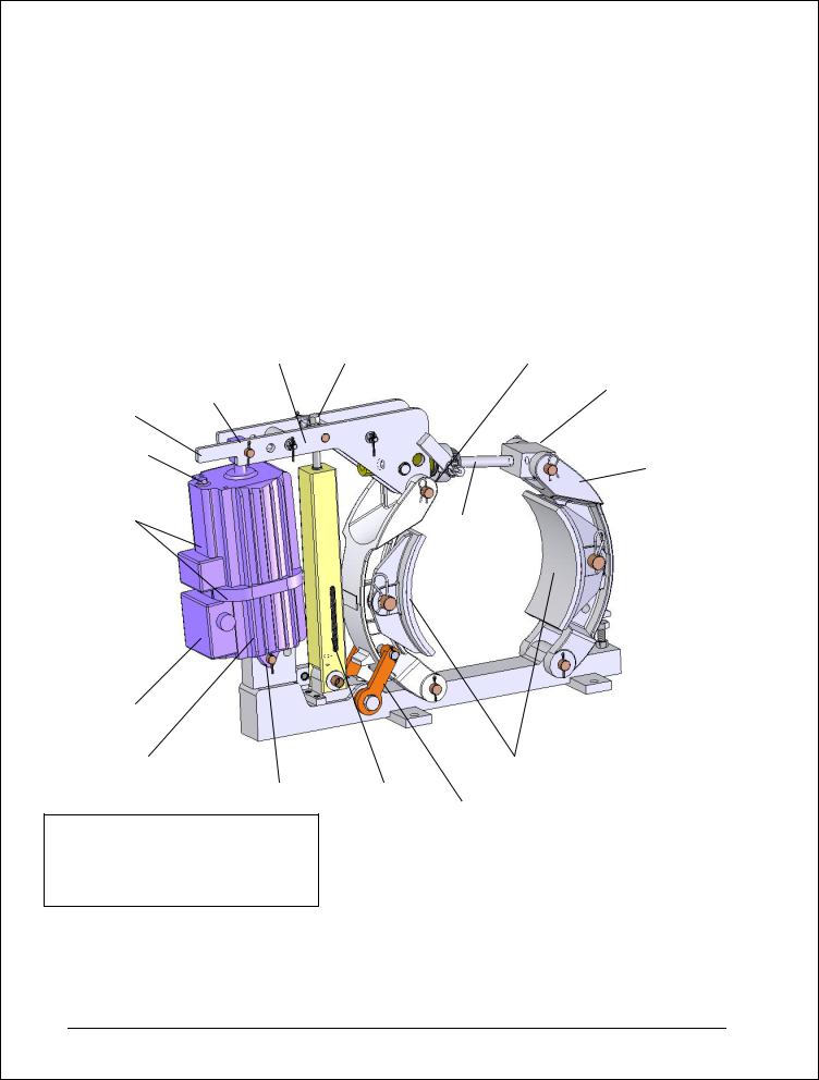
Figure 1a
General Arrangement
MST/E Electric Shoe Brake
With Automatic-Adjustment and Automatic-Equalization
|
|
|
|
|
|
|
|
|
AUTOMATIC |
|
|
|
|
|
|||
|
|
|
|
|
|
|
|
|
ADJUSTMENT (AA) |
|
|
|
|
|
|||
|
|
|
|
|
|
|
|
|
|
|
|
|
|
|
|
|
|
|
|
|
|
|
|
|
|
|
|
|
|
|
|
|
|
|
|
|
|
|
|
|
|
|
|
TORQUE |
|
|
|
|
|
|
|
|
|
|
|
|
|
|
|
|
|
|
|
LINK ARM |
|
|
|
||||
|
|
|
|
|
|
|
|
ADJUSTMENT |
|
|
|
|
|
||||
|
|
|
|
|
|
BRAKE LEVER |
|||||||||||
|
|
|
|
|
|
SCREW |
|
|
(ACTUATOR END) |
|
|
|
|||||
|
|
|
|
|
|
|
|
|
|
|
|
|
|
|
PIVOT |
|
|
|
|
|
|
|
|
|
|
|
|
|
|
|
|
|
|
||
|
|
|
DRIVE END PIVOT |
|
|
|
|
|
|
||||||||
|
|
|
|
|
|
|
|
|
|
|
|||||||
|
|
|
|
|
|
|
|
|
|
BLOCK |
|
||||||
|
|
|
|
|
|
|
|
|
|
|
|
|
|
|
|
|
|
|
|
MANUAL |
|
|
|
|
|
|
|
|
|
|
|
|
|
|
|
|
|
|
|
|
|
|
|
|
|
|
|
|
|
||||
|
|
RELEASE |
|
|
|
|
|
|
|
|
|
|
|
|
|||
|
|
|
|
|
|
|
|
|
|
|
|
|
|
LINK ARM |
|||
|
|
|
|
|
|
|
|
|
|
|
|
|
|
|
|
||
|
FILLER PLUG |
|
|
|
|
|
|
|
|
||||||||
|
|
|
|
|
|
|
|
|
|
|
|
(OUTER END) |
|||||
|
(NOTE 1) |
|
|
|
|
|
|
|
|
|
|
|
|||||
|
|
|
|
|
|
|
|
|
|
|
|
|
|
||||
|
|
|
|
|
|
|
|
|
|
|
|
|
|||||
|
|
|
|
|
|
|
|
|
|
|
|||||||
OPTIONAL |
|
|
|
|
|
|
|
|
|
|
|
||||||
TIME DELAYS |
|
|
|
|
|
|
BRAKE |
|
|
|
|
||||||
|
|
|
|
|
|
|
|
|
|
ROD |
|
|
|
|
|||
|
|
|
|
|
|
|
|
|
|
|
|
|
|
|
|
|
|
TERMINAL
WIRING BOX
HY-TRUST
ACTUATOR
FIXED END PIVOT
NOTE 1:
FILL TO LOWER RIM OF FILLER HOLE. USE ONLY FLUID IDENTIFIED ON THE ACTUATOR NAMEPLATE. DO NOT OVERFILL.
BRAKE
SHOES
EXTERNAL
TORQUE SPRING AUTOMATIC EQUALIZATION
8/17/2006 |
Page 9 of 33 |
MST/E Electric Shoe Brakes Manual |
|
|
560022-R6 |

Chapter 3.0: Application
3.1: The brake covered by this manual is type MST/E. This brake has an adjustable external torque spring and is generally applied on installations where the required torque cannot be predetermined within well defined limits.
3.2: For a given wheel diameter the Association of Iron and Steel Engineers (AISE) determines the prescribed torque, when applied to 30 and 60 minute rated motors in steel mill applications.
3.3: When applied to four quadrant drives or other applications where wheel heating can be accurately predicted, type MST/E brakes can be provided with torque values in excess of the AISE recommendations.
3.4: When the load cycle requires a larger than normal wheel size, as is frequently the case on crane bridge drive, MST/E brakes can be provided with torques lower than AISE for a given wheel size.
3.5: For applications where larger than normal running clearance is required, a larger actuator can be applied to a given brake. Typical would be severe applications where wheel expansion can be considerable or where excessive wheel run-out can be expected.
8/17/2006 |
Page 10 of 33 |
MST/E Electric Shoe Brakes Manual |
|
|
560022-R6 |
Loading...