

Magnetek telePilot TX12M-1, telePilot TX12M-2 Installation And User Manual

IINNSSTTAALLLLAATTIIOONN AANNDD UUSSEERRSS MMAANNUUAALL
TELEMOTIVE
TM
telePilot
TRANSMITTERS
TX12M-1, -2
telePilot Programming is
found on page 69.
N49 W13650 Campbell Drive
Menomonee Falls, WI 53051
Phone: 800-288-8178 Fax: 262-783-3510
Website: http://www.magnetek.com/
RRAADDIIOO
CCOONNTTRROOLL
SSYYSSTTEEMM
TCTX12/TR12-0 Rev. G

This page intentionally left blank.

Table of Contents
1- Service Information .......................................................................................................................... 3
2- Radio Controlled Crane Safety ......................................................................................................... 4
1. Warnings, Cautions and Notes .................................................................................... 4
2. Critical Installation Considerations ............................................................................. 5
3. General ........................................................................................................................ 5
4. Persons Authorized To Operate Radio Controlled Cranes .......................................... 6
5. Training Checklist For Crane Operators ..................................................................... 6
6. Operating Area ............................................................................................................ 7
7. Transmitter Unit .......................................................................................................... 7
8. Operating The Crane ................................................................................................... 7
9. Boarding The Crane .................................................................................................... 9
10. Crane Maintenance and Repair ................................................................................... 9
11. Using The Crane As A Work Platform ..................................................................... 10
12. Condition Of The Radio Controlled Crane ............................................................... 10
13. Batteries .................................................................................................................... 11
3- General System Information ........................................................................................................... 13
1. General System Information ..................................................................................... 13
2. TMS Low Power Signaling ....................................................................................... 13
3. Channel Designations ............................................................................................... 14
4. System Specifications ............................................................................................... 14
5. Transmitter Unit ........................................................................................................ 14
6. Receiver Unit ............................................................................................................ 14
4- Installation Procedure ..................................................................................................................... 15
1. Pre-Installation Considerations ................................................................................. 15
2. Receiver Unit Mounting Location Considerations .................................................... 15
3. Antenna Mounting Considerations ........................................................................... 15
4. Line Input Considerations ......................................................................................... 15
5. Wiring Considerations .............................................................................................. 16
6. Receiver Receiver/Equipment Interface Considerations ........................................... 16
7. Receiver Unit Cabinet Mounting .............................................................................. 16
8. Receiver Installation ................................................................................................. 16
Figure 4-1. Input Power Connections ............................................................................... 17
Figure 4-2A. Receiver Mounting Details Horizontal with Mounting Brackets ................ 18
Figure 4-2B. Receiver Mounting Details Vertical with Mounting Brackets .................... 19
5- Operation ........................................................................................................................................ 20
Figure 5-1. telePilot, Pendant and Membrane Transmitters. .......................................... 20
1. Transmitter Buttons................................................................................................... 20
2. ON/OFF LED Indicator ............................................................................................ 22
3. Low Battery Indicator ............................................................................................... 22
4. Optional 4th Motor Select Indicator. ......................................................................... 22
5. Operation................................................................................................................... 22
6. Additional telePilot Transmitter Operational Features ............................................. 23
7. Battery Replacement ................................................................................................. 26
6- Wiring ............................................................................................................................................. 28
1. Wiring Diagrams ....................................................................................................... 28
2. Installation. ................................................................................................................ 28
3. Alarms and Horns ..................................................................................................... 28
4. Single-Speed Pendant Transmitter Wiring ................................................................ 28
5. Two-Speed Pendant Transmitter Wiring ................................................................... 28
6. Relay Sequencing ...................................................................................................... 28
7. Alarm After E-STOP ................................................................................................ 29
8. Connecting Outputs to Drives ................................................................................... 29
9. Optional Transfer Switch Wiring Configurations ..................................................... 29
Figure 6-1. Legend ........................................................................................................... 29
Figure 6-2. External Transfer Switch Wi ring ................................................................... 30
Figure 6-3A. External Transfer Switch System Wiring ................................................... 31
3

Table of Contents (Continued)
Figure 6-3B. Optional Internal Transfer Switch System Wiring ...................................... 32
Table 1 TR12 Single-Speed Wiring Diagram. Standard Configuration Hoist, Trolley
and Bridge. ................................................................................................................ 33
Table 2(A) TR12 2-Speed Wiring Diagram. Standard Configuration Hoist, Trolley
and Bridge. ................................................................................................................ 35
Table 2(B) TR12 2-Speed Wiring Diagram. 2-Spee d wit h Di rect i o nal Co nt r ols : All
Motions. .................................................................................................................... 37
Table 2(C) TR12 2-Speed Wiring Diagram. 2-Speed, 2-Windings: All Motions. ........... 39
Table 2(D) TR12 2-Speed Wiring Diagram. ACCO Controls: All Motions. ................... 41
Table 2(E) TR12 2-Speed Wiring Diagram. P&H: 2-Speed, 2-Windings for Hoist and
Trolley; Standard Bridge. .......................................................................................... 43
Table 2(F) TR12 2-Speed Wiring Diagram. P&H: 2-Speed, 2-Windings for Hoist;
Standard Trolley and Bridge. .................................................................................... 45
Table 2(G) TR12 2-Speed Wiring Diagram. Demag: 2-Speed, 2-Windings for Hoist;
Standard Trolley and Bridge. .................................................................................... 47
Table 2(H) TR12 2-Speed Wiring Diagram. Standard 2-Speed 4 Motor System. ........... 49
Table 2(I) TR12 2-Speed Wiring Diagram . Standa r d 2-S peed 3, 4 & 5 Motor System
using Select. .............................................................................................................. 51
7- Programming .................................................................................................................................. 53
1. Access Code Programming ....................................................................................... 53
Figure 7-1. Access Code Settings .................................................................................... 53
2. Receiver Frequency Programming ............................................................................ 55
Figure 7-2. RF Receiver Board ........................................................................................ 56
3. Multibox .................................................................................................................... 59
Figure 7-3 SW4 Receiver Multibox Switches .................................................................. 60
4. Custom Receiver Programming ............................................................................... 60
5. Receiver Programming ............................................................................................. 61
6. Membrane Transmitter Programming ....................................................................... 62
Figure 7-4. Repositioning of Membrane Transmitter Motion Switch Functions ............ 64
Figure 7-5. Membrane Transmitter Single-Speed Configurations ................................... 65
7. Pendant Transmitter Programming ........................................................................... 66
Figure 7-6. Repositioning of Pendant Transmitter Motion Switch Functions ................. 68
8. telePilot Programming................................................................................................. 69
Figure 7-7. Single-Speed 10K telePilot Modes ............................................................... 79
Figure 7-8. Single-Speed 10K telePilot Lockout Modes ................................................. 84
Figure 7-9. 2-Speed 9001 and 9101 Series telePilot Functional Mapping ..................... 85
8- RCP Programming ......................................................................................................................... 89
1. Access Codes ............................................................................................................ 89
Figure 8-1. Access Code Settings .................................................................................... 89
2. Multibox .................................................................................................................... 90
3. Programming ............................................................................................................. 91
9- Servicing ....................................................................................................................................... 100
1. Receiver Servicing .................................................................................................. 100
Figure 9-1. Receiver Board Layout ............................................................................... 100
Table 9-1. Receiver Board Diagnostic LED Functions .................................................. 100
2. Receiver Testing ..................................................................................................... 102
Figure 9-2. Receiver Scope Wave Forms ....................................................................... 103
3. Membrane Transmitter Servicing ........................................................................... 104
Figure 9-3. Membrane Transmitter M/C Module E10635 ............................................. 104
4. Pendant Transmitter Servicing ................................................................................ 105
Figure 9-4. Pendant Transmitter M/C Module E10636 .................................................. 105
5. telePilot Servicing .................................................................................................. 106
10- Spare Parts .................................................................................................................................... 107
Figure 10-1 telePilot Exploded View ............................................................................. 110
Appendix A- Transmitter Switch Programming ................................................................................. 111
Section 1 - Service Information
1-1. Service Information.
Thank you for your purchase of the Magnetek’s Telemotive
has set a whole new standard in performance, dependability, and value with its unique new line of
receivers. Without a doubt, our Telemotive telePilot transmitter is the ultimate solution for having
precise, undeterred, and safe control of your material
If your product ever needs modification or service, please contact one of our representatives at the
following locations:
U.S. Service Information
For questions regarding service or technical information, contact:
1.866.MAG.SERV
(1.866.624.7378)
Magnetek Material Handling
N49 W13650 Campbell Drive
Menomonee Falls, WI 53051
Telephone: +1.800.288.8178
Website: www.magnetek.com
e-mail: MHCustomerService@magnetek.com
Fax Numbers
Main: +1.800.298.3503
Sales: +1.262.783.3510
Service: +1.262.783.3508
Canada Service Information:
4090B Sladeview Crescent
Mississauga, Ontario
L5L 5Y5 Canada
Phone: +1.800.792.7253
Fax: +1.905.828.5707
Telemotive Industrial Control trademarks: Telemotive, TMS, telePilot, Laser Guard, Teledrive, Teltec,
TeleMotion are either trademarks or registered trademarks of Telemotive Industrial Controls.
®
Brand telePilot transmitter. Magnetek
Third-party trademarks: All other trademarks, trade names or company names referenced herein are used
for identification only and are the property of their respective owners
CAUTION
DO NOT ATTEMPT TO OPEN OR SERVICE THE TELEPILOT UNIT.
ONLY TRAINED QUALIFIED INDIVIDUALS SHOULD DO SERVICING.
STRICT ANTI-STATIC HANDLING PROCEDURES MUST BE FOLLOWED.
FAILURE TO FOLLOW THIS CAUTION COULD RESULT IN SERIOUS DAMAGE TO
EQUIPMENT AND/OR VOID THE WARRANTY.
.

Section 2 – Radio Controlled Safety
2-1. Warnings, Cautions And Notes.
Through out this document WARNING, CAUTION and NOTE statements have been deliberately placed to
highlight items critical to the protection of personnel and equipment.
WARNING – A warning highlights an essential operating or maintenance procedure, practice, etc. which if not
strictly observed, could result in injury or death of personnel, or long term physical hazards. Warnings are
highlighted as shown below:
WARNING
CAUTION – A caution highlights an essential operating or maintenance procedure, practice, etc. which if not
strictly observed, could result in damage to, or destruction of equipment, or loss of functional effectiveness.
Cautions are highlighted as shown below:
CAUTION
NOTE – A note highlights an essential operating or maintenance procedure, condition or statement. Notes are
shown as below:
NOTE
WARNINGS, CAUTIONS AND NOTES SHOULD NEVER BE DISREGARDED.
The safety rules in this section are not intended to replace any rules or regulations of any applicable local, state, or
federal governing organizations. The following information is intend ed to be used in conjunction with other rules or
regulations already in existence. It is important to read all of the safety information contained in this section before
installing or operating the Radio Control System.
4
Section 2 – Radio Controlled Safety (Continued)
2-2. Critical Installation Considerations.
WARNING
ALL EQUIPMENT MUST HAVE A MAINLINE CONTACTOR INSTALLED AND ALL TRACKED CRANES
AND SIMILAR EQUIPMENT MUST HAVE A BRAKE INSTALLED. FAILURE TO FOLLOW THIS
WARNING COULD RESULT IN SERIOUS INJURY OR DEATH AND DAMAGE TO EQUIPMENT.
WARNING
ON ALL REMOTE CONTROLLED CRANES AN AUDIBLE AND/OR VISU AL WARNING MEANS MUST
BE PROVIDED. THESE AUDIBLE AND/OR VISUAL WARNING DEVICES MUST MEET ALL
GOVERNMENTAL REQUIREMENTS. FAILURE TO FOLLOW THIS WARNING COULD RESULT IN
SERIOUS INJURY OR DEATH AND DAMAGE TO EQUIPME NT.
WARNING
REMOVE ALL ELECTRICAL POWER FROM THE CRANE OR MACHINERY BEFORE ATTEMPTING ANY
INSTALLATION PROCEDURES. DE-ENERGIZE AND TAG OUT ALL SOURCES OF ELECTRICAL POWER
BEFORE TOUCH TESTING ANY EQUIPMENT. FAILURE TO FOLLOW THIS WARNING COULD RESULT
IN SERIOUS INJURY OR DEATH AND DAMAGE TO EQUIPM ENT.
WARNING
THE DIRECT OUTPUTS OF THIS PRODUCT ARE NOT DESIGNED TO INTERFACE DIRECTLY TO TWO
STATE SAFETY CRITICAL MAINTAINED FUNCTIONS, I.E., MAGNETS, VACUUM LIFTS, PUMPS,
EMERGENCY EQUIPMENT, ETC. A MECHANICALLY LOCKING INTERMEDIATE RELAY SYSTEM
WITH SEPARATE POWER CONSIDERATIONS MUST BE PROVIDED. FAILURE TO FOLLOW THIS
WARNING COULD RESULT IN SERIOUS INJURY OR DEATH AND DAMAGE TO EQUIPMENT.
2-3. General.
Radio controlled overhead cranes and other material handling equipment operate in several directions. They are
large, bulky pieces of equipment that handle heavy loads efficiently at high speeds. Quite frequently, the equipment
5

Section 2 – Radio Controlled Safety (Continued)
is operated in areas where people are working on the floor below. The crane operator must exercise extreme caution
at all times. Workers must constantly be alert to avoid accidents. The following rules have been included to indicate
how careful and thoughtful actions may prevent injuries, damage to equipment, or even save a life. If radio
controlled material-handling equipment is operated from the cab, special care must be taken to secure the transmitter. Refer to section titled Section 2-10. Boarding The Crane for specific safety rules.
2-4. Persons Authorized To Operate Radio Controlled Cranes.
Only properly trained persons designated by management should be permitted to operate radio-controlled cranes.
Radio controlled cranes should not be operated by any person who cannot read or understand signs, notices and
operating instructions that pertain to the crane.
Radio controlled cranes should not be operated by any person with insufficient eyesight or hearing or by any person
who may be suffering from a disorder or illness or is taking any medication that may cause loss of crane control.
2-5. Training Checklist For Crane Operators.
Anyone being trained to operate a radio-controlled crane shou ld po ssess as a minimum the fo llowing knowledg e and
skills before operating the crane:
The operator should have knowledge of hazards peculiar to crane operation.
The operator should have knowledge of the safety rules for radio-controlled cranes.
The operator should have the ability to judge distance or moving objects.
The operator should have knowledge of the radio transmitter.
The operator should know the limit switch test procedure.
The operator should know, where authorized, instructions for plug ging motions.
The operator should have knowledge of the use of crane warning lights and alarms.
The operator should have knowledge of observing cran e signal lights.
The operator should be trained to avoid striking any obstructions.
The operator should have knowledge of the proper clearance of lif ts or hooks before moving bridge or trolley.
The operator should have knowledge of the proper stor age space for radio control box when not in use.
The operator should be trained in transferring radio control box to another person.
The operator should be trained how and when to rep ort un safe or unusual operating conditions.
The operator should be trained how to exhibit caution in approaching bridge or trolley bumpers.
The operator should know equipment capacity.
The operator should be trained in making lifts below floor level.
The operator should be trained in making side pulls.
The operator should know how to keep himself and other people clear of lifts and to avoid "pinch" points.
The operator should know cable and hook inspection procedures.
6

Section 2 – Radio Controlled Safety (Continued)
The operator should know procedures for testing hoist, trolley, and bridge brakes.
2-6. Operating Area.
Aisles between equipment, stock, etc., should be free of obstructions so the crane operator can move freely. These
aisles should be a minimum of three feet (one meter) wide, or meet local regulations.
Crane operators should always position themselves for the best view of the crane they are controlling. The crane
should never be operated blindly. The operator should stay as close to the crane load as possible. Operators should
never position themselves in a "pinch" point.
2-7. Transmitter Unit.
Transmitter switches should never be mechanically blocked ON or OFF for any crane motion. When not in use turn
the transmitter OFF. A secure storage space should be provided for the transmitter unit and the transmitter unit
should always be placed there when not in use. This precaution will p revent u nauthorized p eople from operating th e
crane.
Spare transmitters should be stored in a secure storage space and only removed from the storage space after the
current transmitter in use has been turned OFF, taken out of the service area and secured.
2-8. Operating The Crane.
2-8.1. Pre-operation Test.
At the start of each work shift, or when a new operator takes control of the crane, operators shall do as a minimum
the following steps before making lifts with any crane or hoist:
Test the upper-limit switch. Slowly raise the unloaded hook block until the limit switch trips. When checking limit
switches the hoist should be centered over an area free of personnel and equipment.
Visually inspect the hook, load lines, trolley, and bridge as much as possible from the operator's station; in most
instances, this will be the floor of the building.
The bridge and trolley brakes should be tested. On transmitter units equipped with two or more speeds, use the
"lowest" speed when testing braking devices.
When lifting maximum loads, the crane operator should test the hoist brakes by raising the load a few inches from
the floor. If the brakes do not hold, the load should immediately be lowered to the floor.
If provided, test the lower-limit switch.
Test all warning devices.
Test all direction and speed controls for both bridge and trolley travel.
Test all bridge and trolley limit switches, where provided, if operation will bring the equipment in close proximity to
the limit switches.
Test the transmitter emergency stop.
Test the hoist brake to verify there is no drift without a load.
If any crane or hoist fails any of the above tests notify the supervisor and lock out and tag for repair.
7

Section 2 – Radio Controlled Safety (Continued)
2-8.2. General Rules For Operation.
Consult the crane manufacturer, local and governmental regulations for complete rules of operation. In general the
following rules apply to remotely controlled cranes:
The limit switches should never be used as a regular stopping device. They are intended to be protective devices.
Do not make lifts in excess of the equipment rated capacity.
The bridge and trolley should be centered directly over the load when the load is raised to prevent swinging when
making lifts.
A crane designed for this purpose and only with supervisor permission sh ould make side pulls. When a lift is bein g
made, the crane operator should not be positioned in the line of travel. The crane or hoist should be operated from a
position either to the side or opposite from the direction of travel.
When raising or lowering a load, proceed slowly and make certain the load is under control. Tag lines should be
used for handling unusual lengths or bulky loads. Remove slack from chains or slings gradually. Make certain all
personnel are clear before making a lift.
The crane operator should keep all body parts away from the lift and should never be positioned under the lift.
Do not make a lift or move a load if anyone is in a location where they could be struck by the crane or the load.
If the crane operator is being helped, the crane should not be moved until the help er signals they are clear of the
crane and its load.
When a load is hanging from the crane hook and the crane is being moved, the crane operator should sound all
warning devices frequently.
Loads should not be carried over workers heads. If a worker is in the path of crane travel, the crane operator should
stop the crane and clear the area before proceeding.
Runway stops or other cranes should never be bumped into.
When moving the crane, the crane operator should be sure that the hook block and attachments or cables would not
catch on nearby equipment. Slings, chains, or cables should never be dragged along the floor.
Unless required for operator safety, gloves should not be worn when operating the transmitter unit.
All loose materials or parts should be removed from the load before starting the lift.
The crane operator should always hoist lifts high enough to clear all equipment and workers.
The crane operator should never permit anyone to ride on the load or hook except when authorized by the
supervisor.
When another crane on the same runway is stationary with a load hanging, the crane operator should maintain a safe
distance between the stationary crane and the one under their control.
Never leave suspended loads unattended. In an emergency, if the crane is inoperative and a load suspended, notify
the supervisor immediately, barricade and post signs on the floor beneath crane and load.
If power to the crane is removed, the crane operator should turn the transmitter unit OFF and keep it OFF until
power is restored.
If the crane fails to respond properly, the crane operator should stop operation, turn the transmitter unit OFF and
immediately report the condition to their supervisor.
8

Section 2 – Radio Controlled Safety (Continued)
Outdoor cranes, which are subject to movement by wind, should be securely anchored when left unattended. If the
crane is equipped with bridge brakes, the parkin g brake should be set immediately.
2-9. Boarding The Crane.
The crane should not be boarded without permissio n of the supervisor.
The crane operator sho uld turn off the transmitter and take it with them when boarding the crane.
If more than one person is boarding the crane, one person shou ld be made responsible for ensuring all personnel ar e
off the crane before the system is returned to operation.
2-10. Crane Maintenance And Repair.
Qualified personnel must maintain a regularly, i.e., such as monthly, scheduled crane inspection. During this crane
inspection the functionality and safety of the crane remote control must also be tested. The inspection shall include,
but be not limited to items listed in Section 2-13. Condition Of The Radio Controlled Crane. Consult crane
manufacturer, local and governmental regulations for recommended inspection intervals and proper inspection
procedures. Problems noted during this inspection must be repaired before using the crane or the remote control.
Minor repairs include routine maintenance and repairs such as greasing, cleaning and control troubleshooting. All
other repairs should be considered major. If the repair crew consists of more than one person, one person should be
designated as the repair crew leader with the following responsibilities. If the repair crew consists of only on e person, that person has the following responsibilities:
For minor repairs, warning signs should be placed on the floor beneath the crane or suspended from the crane. For
major repairs, the floor area below the crane should be roped off.
When major repairs are to take place, all persons operating other cranes on the same or adjacent runways, if any,
must be notified prior to starting repairs. Notification should include the nature of the repair, safeguards provided,
and movement limitations while repairs are in progress.
When practical, radio controlled cranes which cannot be moved during repairs must be protected against being
bumped by other cranes on the runway. Bumpers should be installed on the exposed side or sides of the crane under
repair. They should be placed as far away as possible. The location of these bumpers should be indicated by red
lights placed so that they are clearly visible to other crane operators traveling on the same runway. When it is not
possible to use bumpers, red lights must be placed so they are clearly visible to other crane operators traveling on the
same runway to indicate the restricted travel zone. All crane operators on the same runway must be informed of the
repair effort and thoroughly instructed to what their operations are limited to and info rmed they will be notified
when repairs are completed.
If any hazard involving the repairmen exists when there is a runway adjacent to the crane under repair, the adjacent
runway should be blocked off as described above. When it is necessary to continue crane operation on the adjacent
runways warning lights must be installed and be visible to operators of cranes on those runways. All cranes should
come to a complete stop prior to entering the restricted area and should proceed through this area only after
receiving permission from a signal person designated for this purpose. Access of persons to and from the crane
being repaired should be under control of the re pai r crew leader.
When boarding the crane, the transmitter should be turned OFF and the transmitter should remain with the repair
crew leader. The leader should board the crane first, open and lock ou t the main switch, and then signal the other
members of the crew it is safe to board the crane.
If work on the crane is to be done in areas not protected by standard handrails, the repair crew should wear approved
safety belts.
All tools and equipment should be moved onto the crane by the use of hand lines. The tools and equipment should
be adequately secured to the hand lines.
9
Section 2 – Radio Controlled Safety (Continued)
If it is necessary to have the crane control circuits energized, all power circuits for crane movement must be opened
prior to energizing the control circuits.
All personnel and tools should be moved to a safe spot before moving the crane during repairs.
Headroom is at a minimum in some crane cabs and on some crane walkways. Caution should be exercised when
boarding or working on cranes. Hard hat s s h ould be worn whenever possible.
When repairs are finished, all personnel, tools and repair equipment should be removed before energizing the crane
circuits.
2-11. Using The Crane As A Work Platform.
When the crane is to be used as a stationary work platform, follow all rules provided in Section 2-10. Crane
Maintenance and Repair. When it is necessary for the crane to be moved from time to time, the crane operator
should board the crane with the transmitter unit. The crane operator shou ld ensure all personnel working on the
crane are in a secure position before moving the crane to the next workstation. It should also be the crane operators’
responsibility to ensure the main switch is open and locked down before work is resumed.
WARNING
THE CRANE OPERATOR SHOULD NOT ATTEMPT TO REPAIR ANY OF THE ITEMS STATED BELOW.
THE CRANE CONDITION SHOULD BE REPORTED TO THE SUPERVISOR. FAILURE TO FOLLOW THIS
WARNING COULD RESULT IN SERIOUS INJURY OR DEATH AND DAMAGE TO EQUIPMENT.
2-12. Condition Of The Radio Controlled Crane.
If the crane fails to respond properly, the crane operator(s) should notify their supervisor. When serious conditions
are noticed (conditions that make the crane unsafe to operate), the crane should be shut d own immediately and the
supervisor notified. The following is a list of some of the items that should be included in the report (see the crane
manufacturer for specifics and possible additional items):
Condition of hoisting cable and hook block (broken strands, clipped sheave wheels, etc.).
Condition of brakes (hoist, trolley, and bridge). (No bluing, rivets on shoes showing, glazing, etc.).
Condition of trolley and rail stops.
Condition of bridge structure.
Condition of festoon system.
Broken welds in any part of the crane structure.
Proper fluid levels and lubrication.
Condition of bridge and trolley stops.
Carbon dust or signs burning on the covers of motors.
Indication of fluid, oil or grease leaks.
Condition of rail sweeps.
10
Section 2 – Radio Controlled Safety (Continued)
Walkways required handrails and ladders are in place, sturdy and not loose.
Protective guards are in place for all moving parts.
Alignment of bridge (screeching or squealing wheels indicate bridge is out of line).
Broken, cracked, or chipped rails on trolley or runway.
Condition of limit switches.
Condition of electrical and mechanical control (electrical or mechanical defects which cause faulty operation such as
un-commanded stopping or starting of any crane motions, warning devices, lights, or auxiliary functions).
Condition of gears (grinding or squealing may indicate foreign materials in gear teeth or a lack of lubrication).
All controls especially E-STOPs are in place and in working order.
Frequent relay tripping of power circuits.
Mechanical parts loosened by vibration (loose rivets, covers, bolts, etc.).
Uneven riding (worn or damaged wheels) .
Condition of collector shoes or bars.
Condition of warning or signal lights and horns (burned out or broken).
2-13. Batteries
WARNING
KNOW AND FOLLOW PROPER BATTERY HANDLING, CHARGING AND DISPOSAL PROCEDURES.
IMPROPER BATTERY PROCEDURES CAN CAUSE BATTERIES TO EXPLODE OR DO OTHER SERIOUS
DAMAGE. FAILURE TO FOLLOW THIS WARNING COULD RESULT IN SERIOUS INJURY OR DEATH
AND DAMAGE TO EQUIPMENT.
2-13.1. Battery Handling.
Use only batteries approved by Telemotive for the specific product.
Do not dispose of a battery pack in fire; it may explode.
Do not attempt to open the battery pack.
Do not short circuit battery.
For intrinsically safe environments only use specified Telemotive intrinsically safe batteries.
Keep the battery pack environment cool during charging operation and storage (i.e., not in direct sunlight or close to
a heating source).
11

Section 2 – Radio Controlled Safety (Continued)
2-13.2. Battery Charging.
For those transmitters equipped with battery chargers, please familiarize all users with the instructions of the charger
before attempting to use.
Use only Telemotive approved chargers for the appropriate battery pack.
Do not attempt to charge non-rechargeable battery packs.
Avoid charging the battery pack for more than 24 hours.
Do not charge batteries in a hazardous environment.
Do not short charger.
Do not attempt to charge a damaged battery.
Do not attempt to use a battery that is leaking, swollen or corroded.
Charger units are not intended for outdoor use. Use only indoors.
2-13.3. Battery Disposal.
Before disposing of batteries consult local and governmental regulatory requirements for proper disposal
procedures.
12

Section 3 – General System Information
3-1. General System Information.
The Telemotive Radio Control System (system) provides remote control of overhead cranes using radio signals. The
system consists of a hand held portable battery operated transmitter unit and a fixed station receiver unit.
A unique 16-bit code (Access Code) for each system is preset in every transmitter and receiver. The receiver
considers any received signal which does not match the receiver access code setting invalid. The Access Code is
made up of 16-bits (65,000 combinations) and no two similar codes are assigned to any two Telemotive systems.
Up to four systems may be used with the same frequency in a 600-foot area (220 meters). Each transmitter operating
on the same frequency may be operated in close proximity, not less than six feet (1.9 meters), to each other.
3-2. TMS Low Power Signaling.
TMS (Time Multiplexed Signaling) is a Telemotive proprietary high-speed packet data system. The system software
is structured to minimize "on the air" transmission time of any transmitter. This allows for multiple transmitters to
share a common frequency. The TMS system is designed so that a transmitter will send a signal for a pr edetermined
ON time, and then will turn OFF. The length of transmitter ON time is referred to as data burst or packet. The packet
length is a function of the quantity of data to be sent, and the data rate (baud). Once the packet is sent, the
transmitter will turn OFF. This allows for other transmitters to time-share the same frequency when a transmitter has
turned OFF. The TMS system software determines the OFF period and repetition rate of the ON period. Since each
system has its own access code, up to 4 transmitters can share and have equal access to the same frequency. TMS
also allows for reduced battery consumption and extended battery life.
These systems have low power pulsed signaling, FCC certified under Part 15 Telecommunications Code of
Regulations, no license is required. The transmitter unit is frequency modulated, low power and is certified under
the appropriate regulations. A license is not required for the transmitter or operator. Modifications to the RF section
of this system are not permitted and could void FCC certification.
13

Section 3 – General System Information (Continued)
3-3. Channel Designations:
AK01 - 439.8 MHz AK06 - 438.8 MHz
AK02 - 439.6 MHz AK07 - 438.6 MHz
AK03 - 439.4 MHz AK08 - 438.4 MHz
AK04 - 439.2 MHz AK09 - 438.2 MHz
AK05 - 439.0 MHz AK10 - 438.0 MHz
AK11 - 437.8 MHz AK16 - 436.8 MHz
AK12 - 437.6 MHz AK17 - 436.6 MHz
AK13 - 437.4 MHz AK18 - 436.4 MHz
AK14 - 437.2 MHz AK19 - 436.2 MHz
AK15 - 437.0 MHz AK20 - 436.0 MHz
AKA00 - 433.125 MHz A KA05 - 434.125 MHz
AKA01 - 433.325 MHz AKA06 - 434.325 MHz
AKA02 - 433.525 MHz A KA07 - 434.525 MHz
AKA03 - 433.725 MHz A KA08 - 434.725 MHz
AKA04 - 433.925 MHz
3-4. System Specifications.
Receiver housing: NEMA 4X, IP67
Transmitter housing: IP65.
Operating Temperature: –22° F to +158° F (-30º C to +70º C) ambient.
Humidity: up to 95 % (non-condensing).
Typical Operating Range: 200 feet (70 meters).
Rating of output relays (includin g Mast er Rel a y ): 16 Am p 277 VAC/24 VDC, 1 HP 240 VAC.
3-5. Transmitter Unit.
The transmitter is battery operated has an ON and OFF switch, E-STOP, motor controls and auxiliary controls used
for such item warning indicators.
LEDs mounted on the front panel provide indication of battery voltage, ON/OFF, Modes and data transmission
status.
A power down feature allows the transmitter and the receiver unit to turn OFF if no keys are pressed for
predetermined number of minutes. The transmitter unit must again be turned ON. The unit uses pulsed operation for
extremely long battery life. A configuration of the system is available without automatic timeout.
Housings are designed of high impact, chemical resistant materials. The antenna for the unit is internal. A strap or
belt is provided for carrying the transmitter.
3-6. Receiver Unit.
The receiver unit consists of a synthesized RF module, built in antenna, integral power supply, microprocessor
controlled output motor control and auxiliary function relays and mainline contactor relay. The receiver unit
contains circuitry, which matches the frequency and access code of the transmitter.
14
Section 4 – Installation Procedure
4-1. Pre-Installation Considerations.
To ensure reliable and safe operation of the system, the following items must be considered before
installing the receiver unit.
WARNING
THE RECEIVER UNIT OR RELAYS ARE NOT RATED AS EXPLOSION PROOF. THE RECEIVER
UNIT MUST NOT BE INSTALLED IN EXPLOSIVE ENVIRONMENTS UNLESS APPROPRIATE
SECONDARY ENCLOSURE MEASURES ARE TAKEN. FAILURE TO FOLLOW THIS WARNING
COULD RESULT IN SERIOUS INJURY OR DEATH AND DAMAGE TO EQUIPMENT.
4-2. Receiver Unit Mounting Location Considerations.
Ensure the mounting location is as far as possible from exposed trolley wires and sources of
electromagnetic or radiated noise
The receiver cabinet is approximately 8" (20 cm) wide by 12" (30 cm) high. A depth of at least 6" (15 cm)
must be provided to allow the cabinet door to open.
The mounting surface must be smooth and continuous. Mounting the cabinet on uneven surfaces could
cause warpage or stress internal components.
The receiver unit may be mounted in any position. Greatest radio control range is obtained when the
receiver unit is mounted with the antenna at the top.
If possible, avoid installing receiver unit to a surface where high vibration or shock is present. If this cannot
be avoided, use appropriate shock mounts.
4-3. Antenna Mounting Considerations.
The antenna is internal and requires no additional mounting. The antenna is at the top of the receiver
cabinet and should not be placed near large metal objects that could be close to or cover the top of the box.
Allow at least six inches above the top of the box for clearance.
4-4. Line Input Considerations.
WARNING
THE UNIT MUST BE WIRED TO THE CORRECT VOLTAGE, AND BE CONNECTED TO THE
CORRECT TERMINAL AS REQUIRED BY THE ACTUAL LINE VOLTAGE. FAILURE FOLLOW
THIS WARNING COULD RESULT IN SERIOUS INJURY OR DEATH AND DAMAGE TO
EQUIPMENT.
The receiver unit has direct connect provisions for operation from 120 (nominal), 50-60 Hz power.
For applications where line voltage deviation exceeds 20% of nominal values if line voltage is not between
95-130 VAC or 190-260 VAC or if 440 VAC p ower is used, a step up or step down transformer must be
used.
15

Section 4 – Installation Procedure (Continued)
NOTE
THE RECEIVER UNIT SHOULD NOT BE CONNECTED TO LINES CONTAINING EXCESSIVE
POWER UP TRANSIENTS OR CONTINUOUS COMMUTATOR NOISE. A LINE CONDITIONER
MAY BE NECESSARY IN SOME INSTALLATIONS.
4-5. Wiring Considerations.
1. Read this manual before installation.
2. Please observe appropriate local and National Electrical Codes when wiring electrical devices.
3. Do not connect or disconnect wiring, or perform circuit checks while the power is turned on.
4. The motor wiring should be in a separate metal conduit from the power wiring, which should also be
in metal conduit.
5. Low voltage wires shall be wired with proper low voltage class wiring procedures.
6. Control wiring as well as antenna wiring shall be in separate conduit and shall be kept as short as
possible.
7. All terminals shall be tightened to specified terminal torque 4.4 IN-LBS (.5 N·m), unless otherwise
specified.
8. Remove excess metal screws, metal filings and wire clippings from inside of unit.
9. Inspect to make sure no exposed wire has contact with any other wiring or terminals.
10. Suppressors are strongly recommended on all contactors.
4-6. Receiver/Equipment Interface Considerations.
All output relay contacts are rated at 16 amps 250 VAC; however, the system rating for the contacts is 5
Amps. Connection to equipment or contactors with higher voltage or current requirements will require
intermediate relays.
All relay outputs are normally open, momentary contact. Since a relay closure is only active while the
transmitter unit key is pressed and held, devices such as lights or lifting magnet must use a mechanical
auxiliary latching relay.
NOTE
FOR INFORMATION ON INTERFACING WITH SYSTEMS WITH HIGH IMPEDANCE INPUTS SEE
SECTION 6-8. CONNECTING OUTPUTS TO DRIVES OR CONTACT TELEMOTIVE.
4-7. Receiver Unit Cabinet Mounting.
Mounting brackets are provided. See Figure 4-2. Receiver Mounting Details. Allow room in mounting the
receiver for the door to swing open
Mount receiver unit cabinet securely to mounting surface. Actual cabinet mounting dimensions are shown
on Figure 4-2. Receiver Mounting Details.
4-8. Receiver Installation.
1. Normally it should not be necessary to set the access codes, as they are preset. Program the unit for any
special crane configurations or other parameters; if desired, see Section 7. Programming for details.
16

Section 4 – Installation Procedure (Continued)
2. Position the receiver. Locate as far as possible from exposed trolley wire and sources of
electromagnetic or radiated noise. Cabinet mounting dimensions and mounting template is on next
page (see Figure 4-2A and B. Receiver Mounting Details). Antenna at top of unit should be kept as
clear as possible of any metal object.
3. Mount the receiver. Mounting brackets are provided to accommodate mounting on to a metal strut
mounting system. The four deep mounting holes in corners of the receiver mounting brackets use
quantity four #10-24 combo drive round head screws 1 ½ “ in length, four #10 lock washers and four
#10-24 hex nuts to mount to the mounting brackets. Lock washers should be used in front of hex nuts.
Four flat washers, .400 I.D. x 1 ½” O.D., are supplied with use for mounting the mounting brackets to
a metal strut.
4. Wire the unit using the appropriate electrical drawings for the specific transmitter and crane orientation
selected (see Section 6. Wiring). For the Membrane or Pendant transmitter, determine crane
orientation; if the direction pair labeled on the transmitter better describes the equipment movement,
use this pair to wire the motor directionals respectively. If you need to remove the main board (4
screws) the antenna unplugs from the RF Receiver, be sure to dress the an tenna cable under the hook
on the RF Receiver when reinstalling the antenna cable.
5. Wire the power to J1 input power connector. The connections are Ground (GND), Neutral (N) and 120
VAC 50-60 Hz (120V).
6. Wiring of the system should now be complete.
See Figure 4-1. Input Power Connections.
7. Stand clear of the crane and apply AC power to receiver unit. Turn switch SW2 OFF (MR relay
control) and SW1 ON (main power switch). Check to see if four LEDs are lit: three green (DS22,
DS23 and DS24) and one red (RF Receiver ON). If none are lit check AC power, power switch SW1
and fuse.
8. Turn transmitter ON. Check to see if the yellow LED is now lit (DSMR1). At this point the MR relay
is disabled; the functions of the transmitter can be checked by noting the turn ing ON of the appropriate
red LEDs next to the control relays (DS7 to DS11). After checking out the functions, turn switch SW2
ON to enable the MR relay; check function and direction by jogging each motion. Installation should
now be complete.
9. If there are any problems, see Section 9. Servicing.
Figure 4-1. Input Power Connections.
1
J1
17
m
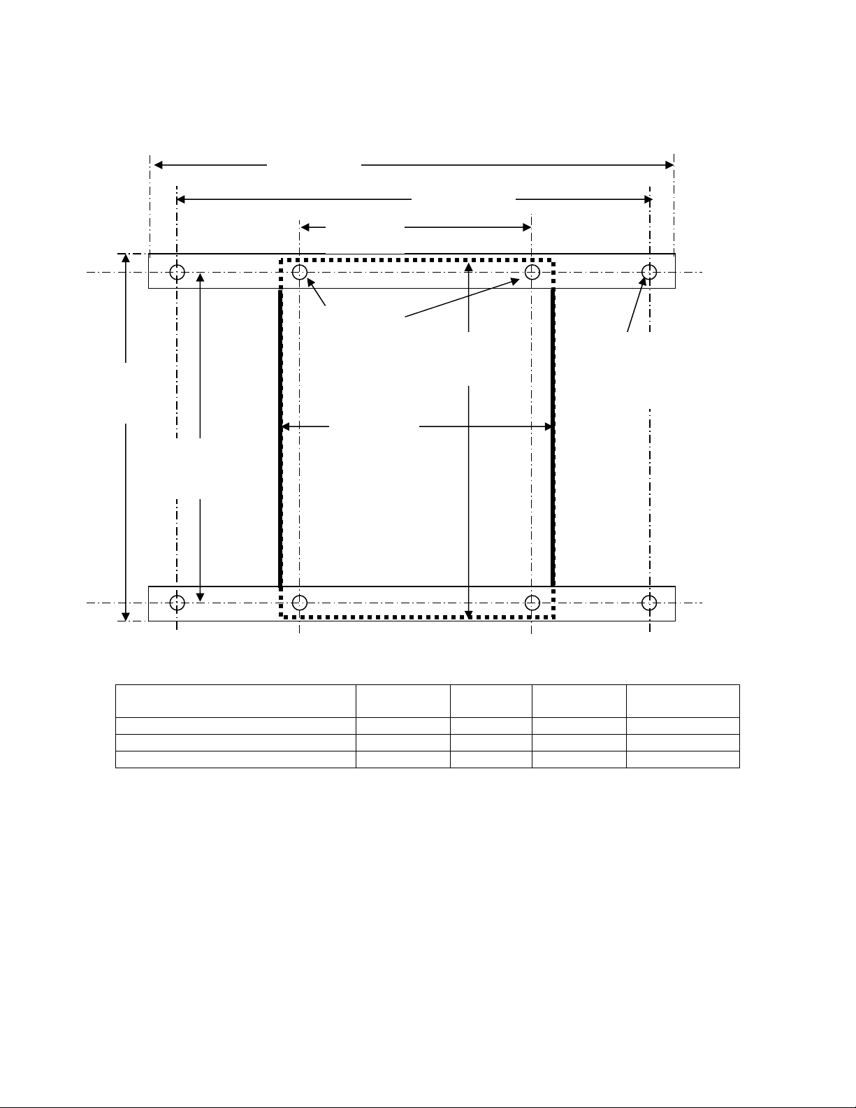
12.02”
305.3 mm
Drawing not to scale.
Section 4 – Installation Procedure (Continued)
11.02”
279.9 mm
16.02”
406.9 mm
7.09”
180 m
.210” DIA.
5.34 mm
hole 4 places
7.87”
200 mm
Receiver shown with
MP10278-0 mounting
brackets attached.
14.02”
356.01 mm
11.81”
300 mm
.281” DIA.
7.14 mm
hole 4 places
Overall Cabinet Depth With door
closed inches
Cabinet 5.26 133.60 12.12 307.98
Cabinet and mounting bracket 5.44 138.07 12.30 312.44
Cabinet, mounting bracket & 1 ½” strut 6.94 176.17 13.80 350.54
With door
closed mm
With door
open inches
With door open
mm
Figure 4-2A. Receiver Mounting Details with
Horizontal Mounting Brackets.
18
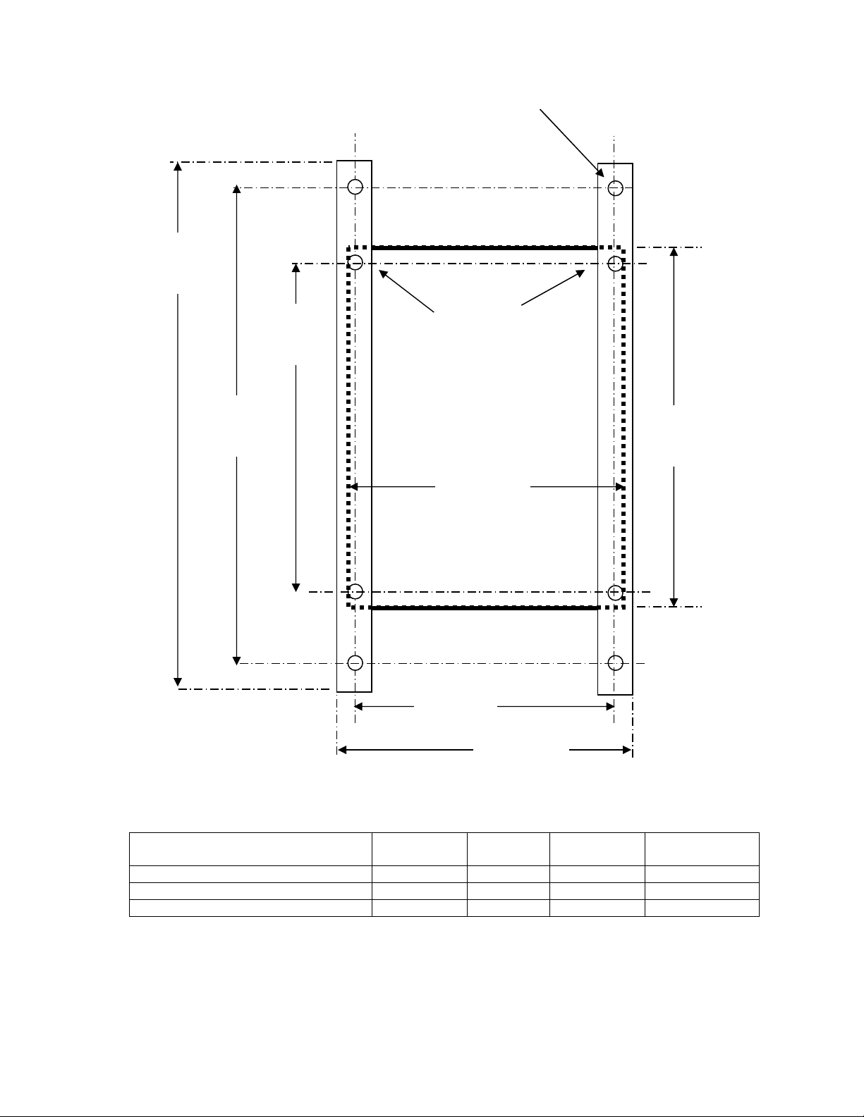
16.02”
406.9 mm
Section 4 – Installation Procedure (Continued)
.281” DIA.
7.14 mm
hole, 4 places
11.02”
279.9 mm
14.02”
356.01 mm
.210” DIA.
5.34 mm
hole, 4 places
Receiver shown with
MP10278-0 mounting
brackets attached.
7.87”
200 mm
7.09”
180 mm
11.81”
300 mm
Drawing not to scale.
Overall Cabinet Depth With door
closed inches
Cabinet 5.26 133.60 12.12 307.98
Cabinet and mounting bracket 5.44 138.07 12.30 312.44
Cabinet, mounting bracket & 1 ½” strut 6.94 176.17 13.80 350.54
8.09”
206.6 mm
With door
closed mm
With door
open inches
With door open
mm
Figure 4-2B. Receiver Mounting Details with
Vertical Mounting Brackets.
19

ON/OFF
Auxiliary
Controls
AUX 1
AUX 2
AUX 3
ON/
OFF
A B
Optional
th
Motor or Select Indicators
4
TX12M-2
2-Speed and Single-Speed telePilot
Figure 5-1. telePilot, Pendant and Membrane
5-1. Transmitter Buttons.
Section 5 – Operation
& Low Battery Indicators
ON/OFF E-STOP
ON/
Motor 1
Dir 1
Dir 2
Motor 2
Dir 1
Dir 2
Motor 3
Dir 1
Dir 2
E-STOP
TX12M-1
OFF
6
5
4
3
2
7
8
9
10
11
12
1
AUX 1
AUX 2
AUX 3
AUX 4
A B BOTH
UP DN
UP
E W
DOWN
NORTH
SOUTH
EAST
WEST
N S
1 2
3
ON OFF
Pendant and Membrane
E
STOP
ON/OFF On the telePilot and Pendant Transmitter ON and OFF is the same button. Pushing this button
toggles between turning the transmitter ON and then sending the ON command to the receiver and sending
the OFF command to the receiver and then turning the transmitter OFF.
NOTE
IN THE TELEPILOT THE TRANSMITTER DOES NOT TURN ON TILL THE ON PUSHBUTTON IS
RELEASED AFTER BEING DEPRESSED TO TURN ON. THE OFF FUNCTION IS IMMEDIATE
UPON DEPRESSING THE ON/OFF PUSHBUTTON.
(Membrane only) ON Turns the transmitter ON and then sends the ON command to the receiver. OFF
Sends the OFF command to the receiver and then turns the transmitter OFF.
E-STOP (EMS) – Stops all equipment movement and disables all functions except Alarm. Reset the
system for normal operation by turning the transmitter “OFF” then “ON”. Use for emergencies only (NOT
FOR NORMAL SHUT DOWN).
NOTE
ON THE TELEPILOT TRANSMITTER THE USER CAN CHOOSE AND CUSTOM LABEL THE
FUNCTIONS FOR A SPECIFIC MOTOR; THE FUNCTIONAL DESIGNATIONS SHOWN BELOW
ARE COMMON AND TRADITIONAL DESIGNATIONS.
Common 2-Speed Designations Listed Below:
Motor 1 Dir 1, (Hoist) UP – Selects hoist movement in the UP direction speed one (first switch position)
or speed two (second switch position).
Motor 1 Dir 2, (Hoist) DN/DOWN – Selects hoist movement in the DOWN direction speed one (first
switch position) or speed two (second switch position).
20

Section 5 – Operation (Continued)
Motor 2 Dir 1, (E Membrane)/NORTH Pendant– Selects the appropriate direction of the bridge or
trolley (depending how unit is wired at installation) speed one (first switch position) or speed two (second
switch position).
Motor 2 Dir 2, (W Membrane)/SOUTH Pendant – Selects the appropriate direction of the bridge or
trolley (depending how unit is wired at installation) speed one (first switch position) or speed two (second
switch position).
Motor 3 Dir 1, (N Membrane)/EAST Pendant – Selects the appropriate direction of the bridge or trolley
(depending how unit is wired at installation) speed one (first switch position) or speed two (second switch
position).
Motor 3 Dir 2, (S Membrane)/WEST Pendant – Selects the appropriate direction of the bridge or trolley
(depending how unit is wired at installation) speed one (first switch position) or speed two (second switch
position).
th
(telePilot Only) Optional 4
The AUX 3 pushbutton can be designated as an auxiliary motor select. As an example, for systems that
have a main and auxiliary hoist, pushing this switch will toggle the function of the set of motor 1
pushbuttons between the outputs for main and auxiliary hoist.
There are two red LEDs above this pushbutton labeled “A” and “B”. The “A” LED comes ON for the main
function and the “B” comes ON for the auxiliary. As the pushbutton is toggled the sequence of outputs and
LEDs is as follows. Normally the main output only is active and the “A” LED is lit. Pushing the pushbu tton
lights only the “B” LED and the auxiliary output only is active. Pushing the pushbutton a second time lights
both “A” and “B” LEDs and both main and auxiliary outputs are active in tandem (this tandem operation
can be disabled See Section 7-8. telePilot Programming). When turning the transmitter ON the default
condition is always “A”.
Motor Or Select with Indicators
A B
This pushbutton can be used with the Select function also. When used for the Select function the “A” and
“B” LEDs work as described in the above paragraph when toggling the Select 1 output and the Select 2
outputs respectively.
1, 2 And 3 (AUX 1, AUX 2, and AUX 3) – Selects the Auxiliary relay(s), which may be used for a
warning device as a horn or other function.
21 11/11/2014
Section 5 – Operation (Continued)
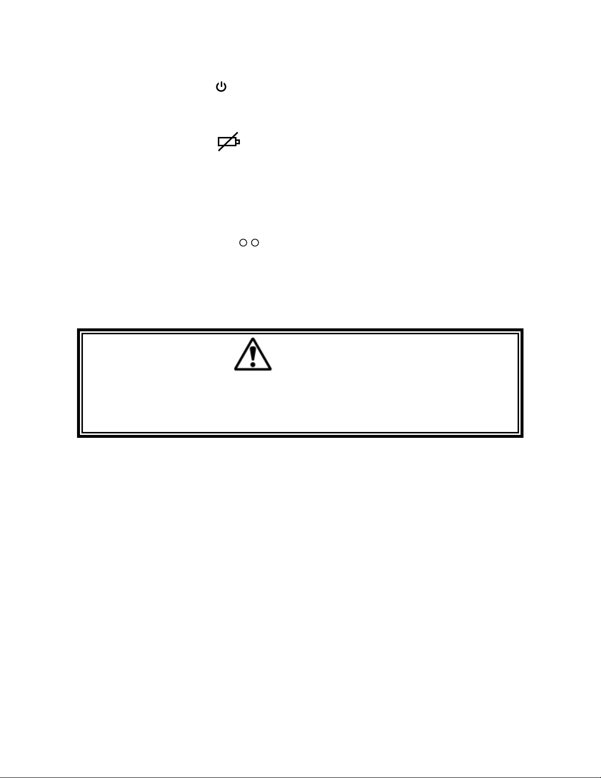
5-2. ON/OFF LED Indicator.
When the transmitter is ON the red LED flashes slowly. When the unit transmits, the red LED flashes
rapidly. Top left indicator on telePilot.
5-3. Low Battery Indication.
In the telePilot transmitter there is a separate low battery indicator located to the right of the ON/OFF
indicator. This is a yellow LED that turns ON solid when it is time to replace the batteries.
For Membrane and Pedant transmitters if the ON/OFF LED indicator does not light at all after turning ON
the transmitter or while operating crane with the transmitter, replace the batteries, as they are weak. See
Section 5-6. Battery Replacement for battery replacement.
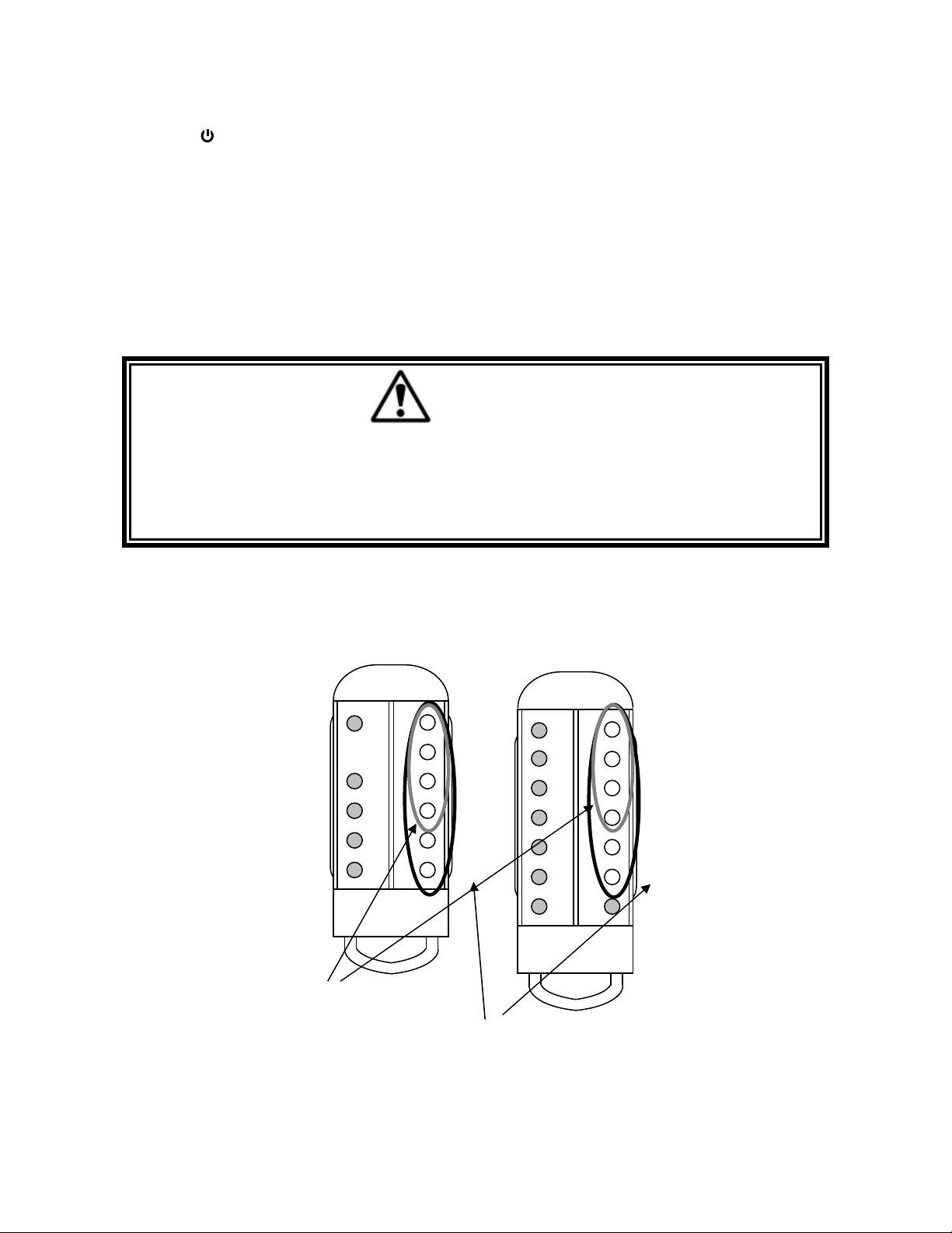
5-4. Optional 4th Motor Select
Indicator.
For two speed telePilots with four motors programmed, this indicator will toggle between “A”, “B” and
both (for units programmed with or without tandem operation). Pressing the pushbutton directly beneath
the indicators toggles the state.
5-5. Operation.
BEFORE TURNING ON OR OPERATING THE CRANE, MAKE SURE ALL PERSONNEL ARE
CLEAR OF THE OPERATING AREA AND NO ONE IS STANDING UNDER THE LOAD. FAILURE
TO FOLLOW THIS WARNING COULD RESULT IN SERIOUS INJURY OR DEATH AND DAMAGE
TO EQUIPMENT.
A B
WARNING
22 11/11/2014
Section 5 – Operation (Continued)
WARNING
WHEN OPERATING THE CRANE FOLLOW LOCAL AND GOVERNMENTAL RULES ON THE USE
OF HORNS AND ALARMS. FAILURE TO FOLLOW THIS WARNING COULD RESULT IN
SERIOUS INJURY OR DEATH AND DAMAGE TO EQUIPMENT.
Make sure that all personnel are clear of the crane movement and no one is under the crane or load.
Turn unit ON by pressing the ON/OFF (ON) button. The red LED ON/OFF indicator should flash rapidly
for a few seconds, indicating the ON command is being sent to the receiver. After the receiver is turned ON
the red LED should flash slowly indicating the transmitter is now ready to send commands.
Perform whatever safety checks are required (see Section 2. Radio Controlled Safety). Operate any horns or
alarms as required by local and governmental regulations.
To operate the crane, press and hold the desired function button to maintain operation. Press the directional
buttons harder to second position to engage second speed for those cranes having 2-speed motors.
Always turn system OFF by pressing the ON/OFF (OFF) button on the transmitter when done with crane
operation. Do not use the E-STOP button as an ON/ OFF button.
In an emergency always hit E-STOP (EMS) immediately. To clear the emergency condition, turn the
transmitter OFF and ON again to resume normal operation.
The receiver will time-out after approximately 15 minutes if there is no activity. The transmitter is
programmed to time-out if not used for 15 minutes for the membrane and pendant as well. For telePilot,
the transmitter time out time is selectable.
WARNING
IN AN EMERGENCY HIT “E-STOP” TO STOP ALL CRANE MOVEMENT. WHEN EMERGENCY
HAS CLEARED TURN THE TRANSMITTER OFF THEN ON AGAIN TO RESUME NORMAL
OPERATION. FAILURE TO FOLLOW THIS WARNING COULD RESULT IN SERIOUS INJURY OR
DEATH AND DAMAGE TO EQUIPMENT.
5-6. Additional telePilot Transmitter Operational Features. (See Section 7-8. telePilot
Programming for information on how to program these features).
telePilot E-STOP Function.
The E-STOP command will be repeatedly sent as long as the E-STOP pushbutton is depressed. The ESTOP is always live on the telePilot transmitter. Upon pushing the E-STOP pushbutton the transmitter will
send an E-STOP command for the last selected Bank even if the unit is turned OFF. This will not work if
the battery is dead.
23 11/11/2014

Section 5 – Operation (Continued)
telePilot Low Battery Shutoff Function.
If the battery gets too low the unit will shut off and send an OFF command to the receiver as it turns OFF.
telePilot Self-Test Function.
If any function key is depressed when the unit turns on the unit will fault, n ot send a turn on command, and
not become operational. The red LED will stay ON till the unit is turned OFF. The unit will frequently scan
nd
the 2
position of the motion switches while the transmitter is ON and if one of th ese is closed without the
first position closed, the unit will fault as above.
telePilot Red LED ON/OFF Indicator.
This red LED, at the upper most left hand side of the transmitter, operates as follows:
Be OFF when the transmitter is OFF.
Flash slowly when the transmitter is ON, but not transmitting. If the transmitter has Bank select
enabled the there will be a number of quick flashes followed by a pause. The number of quick
flashes indicates the Bank the transmitter is in.
Flash rapidly when the transmitter is transmitting, including during E-STOP when the transmitter
is OFF.
Remain ON continuously for: waiting password, un-programmed Bank selected, or a logic or
pushbutton fault.
telePilot Battery Yellow Indicator Light.
The yellow LED to the right of the ON/OFF indicator operates as follows:
Be OFF when the transmitter is OFF.
Be OFF when the transmitter is ON and the battery is good.
Remain ON continuously for a low battery needing replacement.
telePilot Bank Select (Normally Password Protected).
This feature is like having four completely different transmitters in one unit. Up to four banks (operational
configurations) are possible. A Bank is a specific configuration of user-defined parameters including:
System type
Frequency
Access codes
Also: Key arrangement
Relay configuration
Time-out-timer time
Mode selection
Alarm settings
To select a specific bank, The ON/OFF pushbutton is pressed and held down while one of the four upper
most motion pushbuttons (buttons 1 through 4 see Figure 5-2. Bank and Password Input Buttons) is
pressed. Press pushbutton 1 for Bank 1, pushbutton 2 for Bank 2, pushbutton 3 for Bank 3 or pushbutton 4
for Bank 4. While the Bank button is held down release the ON pushbutton and then the Bank button. (The
sequence is important). The transmitter red LED ON/OFF indicator then stays ON (for five seconds) till
the password is entered. Once the password is entered (see below) the transmitter red LED ON/OFF
indicator flashes indicating the current Bank the operator is in while the transmitter is ON and not
transmitting. One flash then a pause repeatedly indicates Bank 1, two quick flashes indicates Bank 2, three
quick flashes and a pause indicates Bank 3 and so on. The transmitter will remember what Bank it is in
even if turned OFF and ON again.
24 11/11/2014
Section 5 – Operation (Continued)
It is not necessary to program all four Banks, if an un-programmed or turned “off” Bank is selected the
ON/OFF indicator will remain ON continuously, the transmitter will send no commands and will turn
itself off shortly.
telePilot Bank Password Protection Function.
This enables the owner to create a four-stroke password word to enable changing Banks. With Password
enabled the operator selects a four-button sequence to enable a Bank after different Bank has been selected
(see above). When the transmitter is turned ON, after Bank Selection is made and the ON/OFF indicator
will remain lit until the correct password sequence is entered with in five seconds. An incorrect password
sequence or failure to enter the sequence in time shuts the unit OFF. The user is allowed to restart and try
again an unlimited amount of times. The Bank Password is the same for all Banks.
WARNING
THIS PASSWORD FUNCTION IS NOT TO BE USED AS A SECURITY DEVICE. THE PURPOSE OF
THIS FUNCTION IS TO PREVENT ACCIDENTAL BANK SWITCHING. THE BEST FORM OF
SECURITY IS ALWAYS TO LOCKUP THE TRANSMITTER WHEN NOT IN SERVICE. FAILURE
TO FOLLOW THIS WARNING COULD RESULT IN SERIOUS INJURY OR DEATH AND DAMAGE
TO EQUIPMENT.
When initially programming the unit the default password is 6, 5, 4, 3. This password can be easily
changed by the PDA during initial programming.
A password is a sequence of four pushbutton entries. These entries are any combination of inputs from the
upper most six buttons on the right hand side of the telePilot transmitter. On 2-Speed transmitters the
second speed is ignored.
1
2
3
4
5
6
1
2
3
4
5
6
Bank Input Buttons
Password Designators for
Programming
Figure 5-2. Bank and Password Input Buttons.
Acceptable sequences could duplicate buttons numbers such as 2, 2, 6, 6 or 1, 1, 1, 4.
25 11/11/2014
Section 5 – Operation (Continued)
NOTE
ALWAYS REMEMBER TO STORE THE PASSWORD IN A SECURE LOCATION FOR ACCESS IF
THE PASSWORD IS LOST OR FORGOTTEN. ONCE THE TRANSMITTER IS PROGRAMMED
THERE IS NO WAY TO DEFEAT THE PASSWORD WITHOUT USING A PDA TO EITHER READ
THE PASSWORD OUT OR REPROGRAM A NEW ONE.
The Bank password can be disabled during initial programming by the PDA.
WARNING
DISABLING THE PASSWORD FUNCTION PUTS THE SYSTEM IN ACTIVE BANK SELECT. THIS
ALLOWS THE CRANE OPERATOR TO SWITCH BETWEEN BANKS QUI CKER. THE OPERATOR
IN THIS MODE MUST BE AWARE AND RESPONSIBLE FOR ALL POSSIBLE CONTROLLED
CRANES. FAILURE TO FOLLOW THIS WARNING COULD RESULT IN SERIOUS INJURY OR
DEATH AND DAMAGE TO EQUIPMENT.
telePilot Time-Out-Timer Function.
The transmitter has a time-out timer and the default condition is 15 minutes. Upon timing out the
transmitter will send an OFF command to the receiver if Auto Turn Off is active. The transmitter time-outtimer function is programmable in minute increments to up to and including 15 minutes. After that it is
programmable in five-minute increments up to and including one hour. Infinite time-out (none) is also
selectable. The time-out-timer measures the time since the last pushbutton stroke and is continuously reset
by any pushbutton activation.
5-7. Battery Replacement.
Membrane And Pendant Battery Replacement.
To replace the batteries, turn the transmitter OFF, and then turn the unit over to access back cover. Twist
half moon shaped battery latch to remove cover. Take out old batteries; replace ALL batteries with new
cells. For the Membrane Transmitter note battery orientation, batteries in backwards will blow fuse.
Replace cover and turn transmitter ON to use. See Section 10. Spare Parts for battery and fuse part
numbers.
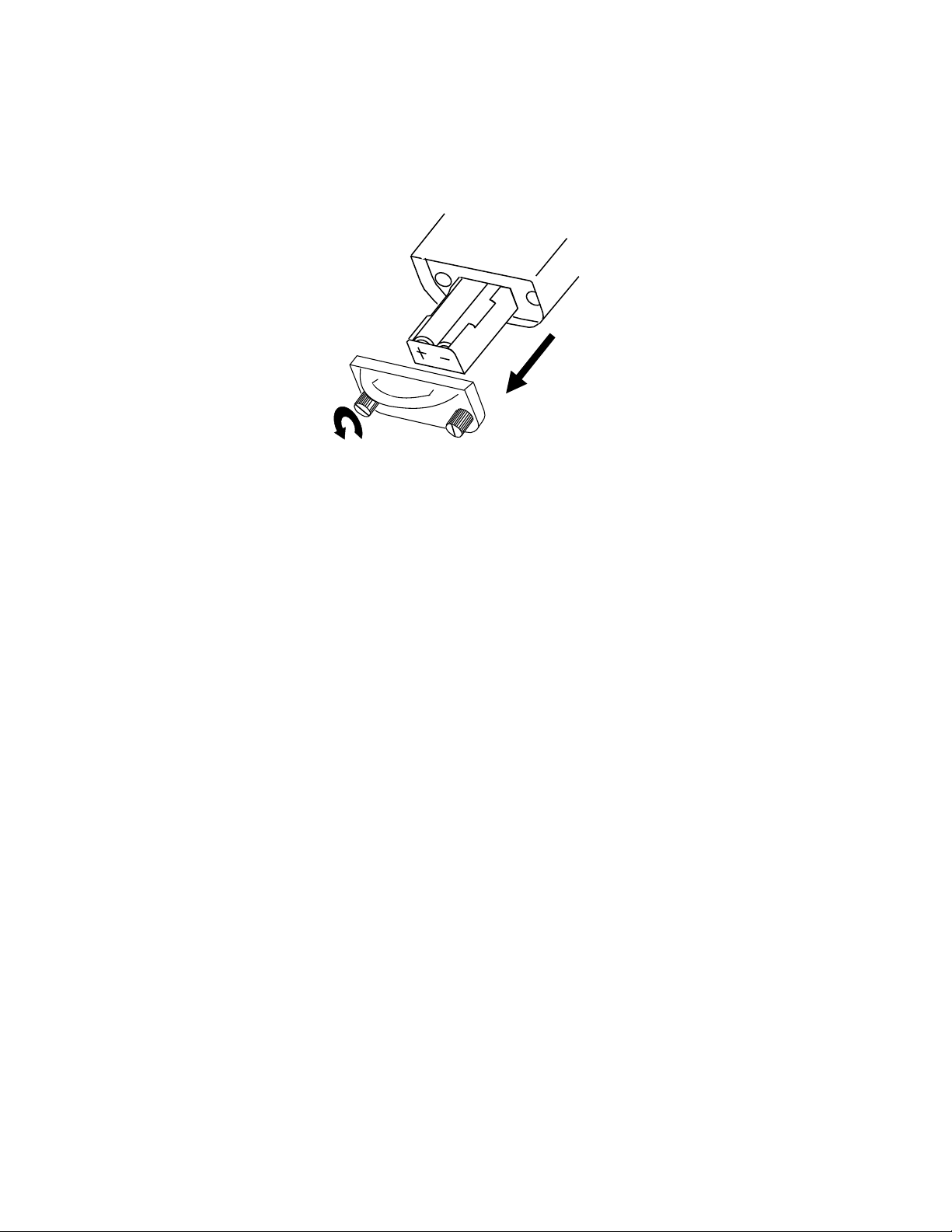
telePilot Battery Replacement.
On the telePilot if the yellow battery indicator light starts to flash replace the battery at th e
earliest opportunity. If the light is on solid replace the battery immediately.
NOTE
THERE IS NO NEED TO RUSH BATTERY REPLACEMENT. THE PROGRAMMING IN THE
telePilot WILL NOT BE LOST BY REMOVAL OF THE BATTERY OR PROLONGED LOSS OF
POWER.
Turn the transmitter OFF, loosen the two thumbscrews on the bottom of the unit and open the unit by
pulling on the belt loop. (See below). Pull out the battery holder until the batteries can be accessed. Do not
pull hard on the battery holder as it is attached to the logic board by a cable. Unsnap the battery cable (for
26 11/11/2014
Section 5 – Operation (Continued)
battery packs) or replace the two “AA” cells (for a battery carrier) and replace the battery(s) with a new
battery(s), noting the polarity for “AA” cells. (Best life can be obtained if the two “AA” batteries used are a
good quality alkaline type, both cells of the same type and from the same manufacturer). Replace the
battery holder, belt loop and tighten the thumbscrews. See Section 9 – Spare Parts for battery part numbers.
Figure 5-3. telePilot Battery Replacement.
27 11/11/2014

Section 6 – Wiring
6-1. Wiring Diagrams.
Your TELEPILOT system comes pre-programmed the following pages in this section have individual
wiring diagrams for different crane configurations. Find the appropriate wiring diagram and if necessary set
the Configuration Switch (SW3 in the transmitter) to match the SW3 Tran smitter Switch Settings shown in
the appropriate diagram. The location of the SW3 for Membrane and Pendant transmitters is shown in
Section 8-1. Servicing. Terminal designators are marked on the wiring diagram corresponding to
designators found on the Receiver Board. For terminal locations see Figure 9-1. Receiver Layout.
After selecting the appropriate motors for each function remember to use the appropriate label on your
telePilot transmitter for describing the appropriate command.
For the Pendant and Membrane transmitters the proper connections to use for the bridge and for the trolley
are best determined by that pair of directional designators (North/South or East/West) best describes the
crane’s movement. Does the bridge travel East/West or North/South? The trolley would use the other
directional pair as the bridge. Care should be taken after a directional pair is selected to make sure the
specific motor directional inputs match the desired direction of the bridge or trolley, i.e., if North/South is
picked for the bridge make sure the South traveling bridge motor directional is wired to the Sou th terminal
of the unit.
Typically in the following wiring diagrams, the bridge is shown as Motor 3 and Trolley as Motor 2. Since
the labeling cannot be easily moved on the Membrane Transmitter keypad, the two directional pairs Motor
2 and 3 can be easily exchanged by turning the dip switch SW3 position 1 in the Membrane Transmitter to
“ON”. See Section 7-6.8. Repositioning of Membrane Transmitter Motion Switch Functions for more
details.
6-2. Installation.
Follow Section 4. Installation Information for instructions on how to install the receiver.
6-3. Alarms And Horns.
Make sure that the installation includes the proper alarms, horns, indicator lights and their associated
controls as required by local and governmental regulations.
6-4. Single-Speed Pendant Transmitter Wiring.
For the Single-Speed Pendant Transmitter the only wiring configuration is the diagram in Section 6.
Wiring. Table 1, TR12 Single-Speed Standard Configuration Hoist, Trolley and Bridge.
6-5. 2-Speed Pendant Transmitter Wiring.
For the 2-Speed TR12 Pendant Transmitter the functional labeling is different than the 2-Sp eed Membrane.
E/W and N/S are exchanged. By setting dip switch SW3 position 1 in the “ON” position the pushbuttons of
the Pendant Transmitter match the directional notations on the 2-speed wiring diagrams in Section 6.
Wiring. Failure to turn switch SW3 position 1 to “ON” will cause EAST/WEST and NORTH/SOUTH to
be exchanged respectively. All other functions will remain the same.
6-6. Relay Sequencing.
When the second speed position is activated the appropriate directional relay is still engaged.
28
 Loading...