

Magnetek Telemotive TR12 inteleSmart Instruction Manual
Telemotive
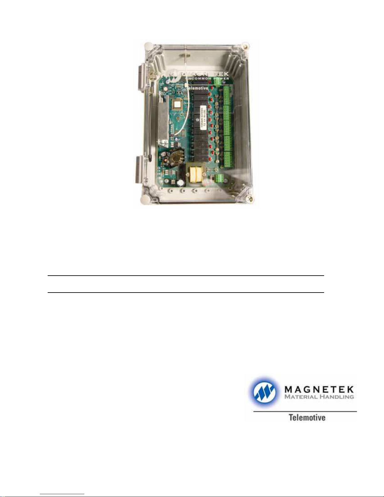
TR12 inteleSmart™ Receiver
Radio Control Equipment
Instruction Manual
TCTR12-PDA Rev. J March 2007
Part Num
©Copyright 2007 Magnetek Material Handling
ber 30033T

Table of Contents
Service Information.....................................................................................................1
Radio Controlled Crane Safety...............................................................................2-8
General System Information.......................................................................................9
Installation............................................................................................................10-12
Operation.......................................................See Appropriate Transmitter Manual
Wiring................................................................................................................... 14-39
Programming........................................................................................................40-53
Servicing................................................................................................................53-57
Spare Parts .................................................................................................................58
Telemotive TR12 inteleSmart Receiver Instruction Manual – 03/01/07

Section 1 – Service Information
Your New Radio Receiver
Thank you for your purchase of Magnetek’s Telemotive® brand TR 12 inteleSmart Receiver. Magnetek
has set a whole new standard in radio-remote performance, dependability, and value with this unique line
of products. Without a doubt, our Telemotive TR 12 inteleSmart Receiver is the ultimate solution for
having precise, undeterred, and safe control of your material.
If your product ever needs modification or service, please contact one of our representatives at the
following locations:
U.S. Service Information
For questions regarding service or technical information, contact 1-866-MAG-SERV
(1-866-624-7378).
Magnetek Material Handling
N49 W13650 Campbell Drive
Menomonee Falls, WI 53051
Telephone: 800-288-8178
Website: www.magnetekmh.com
e-mail: info@magnetekmh.com
Fax Numbers
Main: 800-298-3503
Sales: 262-783-3510
Service: 262-783-3508
For Canada Service Information Contact Berlet Electronics:
Phone: 1-905-564-2710
Fax: 1-905-564-2755
1
Telemotive TR12 inteleSmart Receiver Instruction Manual – 03/01/07
Section 2 - Radio Controlled Crane Safety
Telemotive Industrial Control trademarks:
Boommate, GateMate, 10K, inteleSmart,
Telemotive, telePilot, telePendant, Laser Guard,
Teledrive, Teltec, and TeleMotion are either
trademarks or registered trademarks of Telemotive
Industrial Controls.
Third-party trademarks: All other trademarks, trade
names or company names referenced herein are used
for identification only and are the property of their
respective owners.
CAUTION
ONLY TRAINED QUALIFIED INDIV ID UALS
SHOULD DO SERVICING.
STRICT ANTI-STATIC HANDLING
PROCEDURES MUST BE FOLLOWED.
FAILURE TO FOLLOW THIS CAUTION COULD
RESULT IN SERIOUS DAMAGE TO EQUIPMENT AND/OR VOID THE WARRANTY.
Warnings, Cautions And Notes.
Throughout this document WARNING, CAUTION
and NOTE statements have been deliberately placed
to highlight items critical to the protection of
personnel and equipment.
WARNING – A warning highlights an essential
operating or maintenance procedure, practice, etc.
which if not strictly observed, could result in injury
or death of personnel, or long term physical hazards.
Warnings are highlighted as shown below:
NOTE
WARNINGS, CAUTIONS AND NOTES SHOULD
NEVER BE DISREGARDED.
The safety rules in this section are not
intended to replace any rules or regulations
of any applicable local, state, or federal
governing organizations. The following
information is intended to be used in
conjunction with other rules or regulations
already in existence. It is important to read
all of the safety information contained in this
section before installing or operating the
Radio Control System.
2-1. Critical Installation Considerations.
WARNING
ALL EQUIPMENT MUST HAVE A MAINLINE
CONTACTOR INSTALLED AND ALL TRACKED
CRANES AND SIMILAR EQUIPMENT MUST
HAVE A BRAKE INSTALLED. FAILURE TO
FOLLOW THIS WARNING COULD RESULT IN
SERIOUS INJURY OR DEATH AND DAMAGE
TO EQUIPMENT.
WARNING
CAUTION – A caution highlights an essential
operating or maintenance procedure, practice, etc.
which if not strictly observed, could result in damage
to, or destruction of equipment, or loss of functional
effectiveness. Cautions are highlighted as shown
below:
CAUTION
NOTE – A not
maintenance procedure, condition or statement. Notes
are shown as below:
e highlights an essential operating or
2
WARNING
ON ALL REMOTE CONTROLLED CRANES AN
AUDIBLE AND/OR VISUAL WARNING MEANS
MUST BE PROVIDED. THESE AUDIBLE
AND/OR VISUAL WARNING DEVICES MUST
MEET ALL GOVERNMENTAL REQUIREMENTS. FAILURE TO FOLLOW THIS WARNING COULD RESULT IN SERIOUS INJURY OR
DEATH AND DAMAGE TO EQUIPMENT.
Telemotive TR12 inteleSmart Receiver Instruction Manual – 03/01/07
Section 2 - Radio Controlled Crane Safety (continued)
WARNING
REMOVE ALL ELECTRICAL POWER FROM
THE CRANE OR MACHINERY BEFORE ATTEMPTING ANY INSTALLATION PROCEDURES. DE-ENERGIZE AND TAG OUT ALL
SOURCES OF ELECTRICAL POWER BEFORE
TOUCH TESTING ANY EQUIPMENT. FAILURE
TO FOLLOW THIS WARNING COULD RESULT
IN SERIOUS INJURY OR DEATH AND DAMAGE TO EQUIPMENT.
WARNING
THE DIRECT OUTPUTS OF THIS PRODUCT
ARE NOT DESIGNED TO INTERFACE DIRECTLY TO TWO STATE SAFETY CRITICAL
MAINTAINED FUNCTIONS, I.E., MAGNETS,
VACUUM LIFTS, PUMPS, EMERGENCY
EQUIPMENT, ETC. A MECHANICALLY LOCKING INTERMEDIATE RELAY SYSTEM WITH
SEPARATE POWER CONSIDERATIONS MUST
BE PROVIDED. FAILURE TO FOLLOW THIS
WARNING COULD RESULT IN SERIOUS INJURY OR DEATH AND DAMAGE TO EQUIPMENT.
2-2. General.
2-3. Persons Authorized To Operate Radio
Controlled Cranes.
Only properly trained persons designated by
management should be permitted to operate radiocontrolled cranes.
Radio controlled cranes should not be operated by
any person who cannot read or understand signs,
notices and operating instructions that pertain to the
crane.
Radio controlled cranes should not be operated by
any person with insufficient eyesight or hearing or by
any person who may be suffering from a disorder or
illness or is taking any medication that may cause
loss of crane control.
2-4. Training Checklist For Crane Operators.
Anyone being trained to operate a radio-controlled
crane should possess as a minimum the following
knowledge and skills before operating the crane:
The operator should have knowledge of hazards
peculiar to crane operation.
The operator should have knowledge of the safety
rules for radio-controlled cranes.
The operator should have the ability to judge distance
or moving objects.
The operator should have knowledge of the radio
transmitter.
The operator should know the limit switch test
procedure.
Radio controlled overhead cranes and other material
handling equipment operate in several directions.
They are large, bulky pieces of equipment that handle
heavy loads efficiently at high speeds. Quite
frequently, the equipment is operated in areas where
people are working on the floor below. The crane
operator must exercise extreme caution at all times.
Workers must constantly be alert to avoid accidents.
The following rules have been included to indicate
how your careful and thoughtful action s may prevent
injuries, damage to equipment, or even save a life. If
radio controlled material-handling equipment is
operated from the cab, special care must be taken to
secure the transmitter. Refer to section titled Section
2-9. Boarding The Crane for specific safety rules.
3
The operator should know, where authorized,
instructions for plugging motions.
The operator should have knowledge of the use of
crane warning lights and alarms.
The operator should have knowledge of observing
crane signal lights.
The operator should be trained to avoid striking any
obstructions.
The operator should have knowledge of the proper
clearance of lifts or hooks before moving bridge or
trolley.
The operator should have knowledge of the proper
storage space for radio transmitter when not in use.
Telemotive TR12 inteleSmart Receiver Instruction Manual – 03/01/07

Section 2 - Radio Controlled Crane Safety (continued)
The operator should be trained in transferring radio
transmitter to another person.
The operator should be trained how and when to
report unsafe or unusual operating conditions.
The operator should be trained how to exhibit caution
in approaching bridge or trolley bumpers.
Before putting the transmitter in service the
transmitter unit should be inspected for any damage
or excessive wear. Units with, but not limited to, any
of the following: broken housings, switches or
handles, missing battery doors, switch boots or
switch knobs should be repaired before putting into
service.
2-7. Operating The Crane.
The operator should know equipment capacity.
The operator should be trained in making lifts below
floor level.
The operator should be trained in making side pulls.
The operator should know how to keep himself and
other people clear of lifts and to avoid "pinch" points.
The operator should know cable and hook inspection
procedures.
The operator should know procedures for testing
hoist, trolley, and bridge brakes.
2-5. Operating Area.
Aisles between equipment, stock, etc., should be free
of obstructions so the crane operator can move freely.
These aisles should be a minimum of three feet (one
meter) wide, or meet local regulations.
Crane operators should always position themselves
for the best view of the crane they are controlling.
The crane should never be operated blindly. The
operator should stay as close to the crane load as
possible. Operators should never position themselves
in a "pinch" point.
2-6. Transmitter Unit.
Transmitter switches should never be mechanically
blocked ON or OFF for any crane motion. When not
in use turn the transmitter OFF. A secure storage
space should be provided for the transmitter unit and
the transmitter unit should always be placed there
when not in use. This precaution will prevent
unauthorized people from operating the crane.
2-7.1. Pre-operation Test.
At the start of each work shift, or when a new operator takes control of the crane, operators shall do as
a minimum the following steps before making lifts
with any crane or hoist:
Test the upper-limit switch. Slowly raise the
unloaded hook block until the limit switch trips.
When checking limit switches the hoist should be
centered over an area free of personnel and
equipment.
Visually inspect the hook, load lines, trolley, and
bridge as much as possible from the operator's
station; in most instances, this will be the floor of the
building.
The bridge and trolley brakes should be tested. On
transmitter units equipped with two or more speeds,
use the "lowest" speed when testing braking devices.
When lifting maximum loads, the crane operator
should test the hoist brakes by raising the load a few
inches from the floor. If the brakes do not hold, the
load should immediately be lowered to the floor.
If provided, test the lower-limit switch.
Test all warning devices.
Test all direction and speed controls for both bridge
and trolley travel.
Test all bridge and trolley limit switches, where
provided, if operation will bring the equipment in
close proximity to the limit switches.
Test the transmitter emergency stop.
Spare transmitters should be stored in a secure
storage space and only removed from the storage
space after the current transmitter in use has been
turned OFF, taken out of the service area and
secured.
4
Test the hoist brake to verify there is no drift without
a load.
If any crane or hoist fails any of the above tests notify
the supervisor and lock out and tag for repair.
Telemotive TR12 inteleSmart Receiver Instruction Manual – 03/01/07

Section 2 - Radio Controlled Crane Safety (continued)
2-7.2. General Rules For Operation.
Consult the crane manufacturer, local and
governmental regulations for complete rules of
operation. In general the following rules apply to
remotely controlled cranes:
The limit switches should never be used as a
regular stopping device. They are intended to be
protective devices.
When moving the crane, the crane operator should
be sure that the hook block and attachments or
cables would not catch on nearby equipment.
Slings, chains, or cables should never be dragged
along the floor.
Unless required for operator safety, gloves should
not be worn when operating the transmitter unit.
All loose materials or parts should be removed
from the load before starting the lift.
Do not make lifts in excess of the equipment rated
capacity.
The bridge and trolley should be centered directly
over the load when the load is raised to prevent
swinging when making lifts.
A crane designed for this purpose and only with
supervisor permission should make side pulls.
When a lift is being made, the crane operator
should not be positioned in the line of travel. The
crane or hoist should be operated from a position
either to the side or opposite from the direction of
travel.
When raising or lowering a load, proceed slowly
and make certain the load is under control. Tag
lines should be used for handling unusual lengths
or bulky loads. Remove slack from chains or slings
gradually. Make certain all personnel are clear
before making a lift.
The crane operator should keep all body parts away
from the lift and should never be positioned under
the lift.
Do not make a lift or move a load if anyone is in a
location where they could be struck by the crane or
the load.
If the crane operator is being helped, the crane
should not be moved until the helper signals they
are clear of the crane and its load.
When a load is hanging from the crane hook and
the crane is being moved, the crane operator should
sound all warning devices frequently .
The crane operator should always hoist lifts high
enough to clear all equipment and workers.
The crane operator should never permit anyone to
ride on the load or hook except when authorized by
the supervisor.
When another crane on the same runway is stationary with a load hanging, the crane operator
should maintain a safe distance between the stationary crane and the one under their control.
Never leave suspended loads unattended. In an
emergency, if the crane is inoperative and a load
suspended, notify the supervisor immediately,
barricade and post signs on the floor beneath crane
and load.
If power to the crane is removed, the crane operator should turn the transmitter unit OFF and
keep it OFF until power is restored.
If the crane fails to respond properly, the crane
operator should stop operation, turn the transmitter
unit OFF and immediately report the condition to
their supervisor.
Outdoor cranes, which are subject to movement by
wind, should be securely anchored when left
unattended. If the crane is equipped with bridge
brakes, the parking brake should be set immediately.
2-8. Boarding The Crane.
The crane should not be boarded without permission of the supervisor.
Loads should not be carried over workers heads. If
a worker is in the path of crane travel, the crane
operator should stop the crane and clear the area
before proceeding.
Runway stops or other cranes should never be
bumped into.
5
The crane operator should turn off the transmitter
and take it with them when boarding the crane.
If more than one person is boarding the crane, one
person should be made responsible for ensuring all
personnel are off the crane before the system is
returned to operation.
Telemotive TR12 inteleSmart Receiver Instruction Manual – 03/01/07

Section 2 - Radio Controlled Crane Safety (continued)
2-9. Crane Maintenance And Repair.
Qualified personnel must maintain a regularly, i.e.,
such as monthly, scheduled crane inspection.
During this crane inspection the functionality and
safety of the crane remote control must also be
tested. The inspection shall include, but be not
limited to items listed in Section 2-12 Condition Of
The Radio Controlled Crane. Consult crane
manufacturer, local and governmental regulations
for recommended inspection intervals and proper
inspection procedures. Problems noted during this
inspection must be repaired before using the crane
or the remote control.
Minor repairs include routine maintenance and
repairs such as greasing, cleaning and control
troubleshooting. All other repairs should be considered major. If the repair crew consists of more
than one person, one person should be designated
as the repair crew leader with the following
responsibilities. If the repair crew consists of only
one person, that person has the following
responsibilities:
For minor repairs warning signs should be placed
on the floor beneath the crane or suspended from
the crane. For major repairs, the floor area below
the crane should be roped off.
When major repairs are to take place, all persons
operating other cranes on the same or adjacent
runways, if any, must be notified prior to starting
repairs. Notification should include the nature of
the repair, safeguards provided, and movement
limitations while repairs are in progress.
When practical, radio controlled cranes which
cannot be moved during repairs must be protected
against being bumped by other cranes on the
runway. Bumpers should be installed on the
exposed side or sides of the crane under repair.
They should be placed as far away as possible. The
location of these bumpers should be indicated by
red lights placed so that they are clearly visible to
other crane operators traveling on the same runway.
When it is not possible to use bumpers, red lights
must be placed so they are clearly visible to other
crane operators traveling on the same runway to
indicate the restricted travel zone. All crane operators on the same runway must be informed of the
repair effort and thoroughly instructed to what their
operations are limited to and informed they will be
notified when repairs are completed.
If any hazard involving the repairperson exists
when there is a runway adjacent to the crane under
repair, the adjacent runway should be blocked off
as described above. When it is necessary to
Telemotive TR12 inteleSmart Receiver Instruction Manual – 03/01/07
6
continue crane operation on the adjacent runways
warning lights must be installed and be visible to
operators of cranes on those runways. All cranes
should come to a complete stop prior to entering
the restricted area and should proceed through this
area only after receiving permission from a signal
person designated for this purpose. Access of
persons to and from the crane being repaired should
be under control of the repair crew leader.
When boarding the crane, the transmitter should be
turned OFF and the transmitter should remain with
the repair crew leader. The leader should board the
crane first, open and lock out the main switch, and
then signal the other members of the crew it is safe
to board the crane.
If work on the crane is to be done in areas not
protected by standard handrails, the repair crew
should wear approved safety belts.
All tools and equipment should be moved onto the
crane by the use of hand lines. The tools and
equipment should be adequately secured to the
hand lines.
If it is necessary to have the crane control circuits
energized, all power circuits for crane movement
must be opened prior to energizing the control
circuits.
All personnel and tools should be moved to a safe
spot before moving the crane during repairs.
Headroom is at a minimum in some crane cabs and
on some crane walkways. Caution should be
exercised when boarding or working on cranes.
Hard hats should be worn whenever possible.
When repairs are finished, all personnel, tools and
repair equipment should be removed before
energizing the crane circuits.
2-10. Using The Crane As A Work Platform.
When the crane is to be used as a stationary work
platform, follow all rules provided in Section 2-8
Crane Maintenance and Repair. When it is
necessary for the crane to be moved from time to
time, the crane operator should board the crane
with the transmitter unit. The crane operator should
ensure all personnel working on the crane are in a
secure position before moving the crane to the next
workstation. It should also be the crane operators
responsibility to ensure the main switch is open and
locked down before work is resumed.
Section 2 - Radio Controlled Crane Safety (continued)
Broken, cracked, or chipped rails on trolley or
runway.
WARNING
THE CRANE OPERATOR SHOULD NOT
ATTEMPT TO REPAIR ANY OF THE ITEMS
STATED BELOW. THE CRANE CONDITION
SHOULD BE REPORTED TO THE
SUPERVSOR. FAILURE TO FOLLOW THIS
WARNING COULD RESULT IN SERIOUS
INJURY OR DEATH AND DAMAGE TO
EQUIPMENT.
2-11. Condition Of The Radio Controlled Crane.
If the crane fails to respond properly, the crane
operator(s) should notify their supervisor. When
serious conditions are noticed (conditions that
make the crane unsafe to operate), the crane should
be shut down immediately and the supervisor
notified. The following is a list of some of the items
that should be included in the report. (See the crane
manufacturer for specifics and possible additional
items):
Condition of hoisting cable and hook block (broken
strands, clipped sheave wheels, etc.).
Condition of brakes (hoist, trolley, and bridge). (No
bluing, rivets on shoes showing, glazing, etc.).
Condition of limit switches.
Condition of electrical and mechanical control
(electrical or mechanical defects which cause faulty
operation such as un-commanded stopping or
starting of any crane motions, warning devices,
lights, or auxiliary functions).
Condition of gears (grinding or squealing may
indicate foreign materials in gear teeth or a lack of
lubrication.
All controls especially ESTOPs are in place and in
working order.
Frequent relay tripping of power circuits.
Mechanical parts loosened by vibration (loose
rivets, covers, bolts, etc.).
Uneven riding (worn or damaged wheels) .
Condition of collector shoes or bars.
Condition of warning or signal lights and horns.
(Burned out or broken).
2-12. Batteries
Condition of trolley and rail stops.
Condition of bridge structure.
Condition of festoon system.
Broken welds in any part of the crane structure.
Proper fluid levels and lubrication.
Condition of bridge and trolley stops.
Carbon dust or signs burning on the covers of
motors.
Indication of fluid, oil or grease leaks.
Condition of rail sweeps.
Walkways required handrails and ladders are in
place, sturdy and not loose.
Protective guards are in place for all moving parts.
Alignment of bridge (screeching or squealing
wheels indicate bridge is out of line).
WARNING
KNOW AND FOLLOW PROPER BATTERY
HANDLING, CHARGING AND DISPOSAL
PROCEDURES. IMPROPER BATTERY PROCEDURES CAN CAUSE BATTERIES TO
EXPLODE OR DO OTHER SERIOUS DAMAGE.
FAILURE TO FOLLOW THIS WARNING
COULD RESULT IN SERIOUS INJURY OR
DEATH AND DAMAGE TO EQUIPMENT.
2-12.1. Battery Handling.
Use only batteries approved by Telemotive for the
specific product.
Do not dispose of a battery pack in fire; it may
explode.
Do not attempt to open the battery pack.
7
Telemotive TR12 inteleSmart Receiver Instruction Manual – 03/01/07

Section 2 - Radio Controlled Crane Safety (continued)
Do not short circuit battery.
Do not attempt to use a battery that is leaking,
swollen or corroded.
For intrinsically safe environments only use
specified Telemotive intrinsically safe batteries.
Keep the battery pack environment cool during
charging operation and storage, (i.e., not in direct
sunlight or close to a heating source).
Do not attempt to charge non-rechargeable battery
packs.
Avoid charging the battery pack for more than 24
hours.
Do not charge batteries in a hazardous
environment.
Do not short the charger.
2-12.2. Battery Charging.
For those transmitters equipped with battery
chargers, please familiarize all users with the
instructions of the charger before attempting to use.
Use only Telemotive approved chargers for the
appropriate battery pack.
Do not attempt to charge a damaged battery.
Charger units are not intended for outdoor use. Use
only indoors.
2-12.3. Battery Disposal.
Before disposing of batteries consult local and
governmental regulatory requirements for proper
disposal procedures.
8
Telemotive TR12 inteleSmart Receiver Instruction Manual – 03/01/07

Section 3 - General System Information
3-1. General System Information.
The Telemotive Radio Control System (system)
provides remote control of overhead cranes using
radio signals. The system consists of a hand held
portable battery operated transmitter unit and a
fixed station receiver unit.
A unique 16-bit code (Access Code) for each
system is preset in every transmitter and receiver.
The receiver considers any received signal, which
does not match the receiver access code setting,
invalid. The Access Code is made up of 16-bits
(65,000 combinations) and no two similar codes are
assigned to any two Telemotive systems.
Up to four systems may be used with the same
frequency in a 600-foot area (220 meters). Each
transmitter operating on the same frequency may be
operated in close proximity, not less than six feet
(1.9 meters) to each other.
3-2. TMS Low Power Signaling.
TMS (Time Multiplexed Signaling) is a Telemotive
proprietary high-speed packet data system. The
system software is structured to minimize "on the
air" transmission time of any transmitter. This
allows for multiple transmitters to share a common
frequency. The TMS system is designed so that a
transmitter will send a signal for a predetermined
ON time, and then will turn OFF. The length of
transmitter ON time is referred to as data burst or
packet. The packet length is a function of the
quantity of data to be sent, and the data rate (baud).
Once the packet is sent, the transmitter will turn
OFF. This allows for other transmitters to timeshare the same frequency when a transmitter has
turned OFF. The TMS system software determines
the OFF period and repetition rate of the ON
period. Since each system has its own access code,
up to 4 transmitters can share and have equal access
to the same frequency. TMS also allows for
reduced battery consumption and extended battery
life.
These systems have low power pulsed signaling,
FCC certified under Part 15 Telecommunications
Code of Regulations, no license is required. The
transmitter unit is frequency modulated, low power
and is certified under the appropriate regulations. A
license is not required for the transmitter or
operator. Modifications to the RF section of this
system are not permitted and could void FCC
certification.
3-3. Channel Designations:
Indicator Channel Actual
Count Designator Frequency
01. AK01 439.8 MHz
02. AK02 439.6 MHz
03. AK03 439.4 MHz
04. AK04 439.2 MHz
05. AK05 439.0 MHz
06. AK06 438.8 MHz
07. AK07 438.6 MHz
08. AK08 438.4 MHz
09. AK09 438.2 MHz
10. AK10 438.0 MHz
11. AK11 437.8 MHz
12. AK12 437.6 MHz
13. AK13 437.4 MHz
14. AK14 437.2 MHz
15. AK15 437.0 MHz
16. AK16 436.8 MHz
Indicator Channel Actual
17. AK17 436.6 MHz
18. AK18 436.4 MHz
19. AK19 436.2 MHz
20. AK20 436.0 MHz
21. AKA00 433.125 MHz
22. AKA01 433.325 MHz
23. AKA02 433.525 MHz
24. AKA03 433.725 MHz
25. AKA04 433.925 MHz
26. AKA05 434.125 MHz
27. AKA06 434.325 MHz
28. AKA07 434.525 MHz
29. AKA08 434.725 MHz
30. AK38 432.4 MHz
31. AK50 430.0 MHz
3-4. Receiver Specifications.
Receiver housing: NEMA 4X, IP67
Operating Temperature: –22° F to +158° F (-30
degrees C to +70 degrees C) ambient.
Humidity: up to 95 % (non-condensing).
Typical Operating Range: 300 feet (91 meters).
Relays are rated for 16 Amps 277VAC/24VDC, 1
HP 240VAC for maximum life and surge
protection, they are fused with 2AG Slow Blo fuses
and protected with MOV’s.
3-5. Receiver Unit.
The receiver unit consists of a synthesized RF
module, antenna, integral power supply,
microprocessor controlled output motor control and
auxiliary function relays and mainline contactor
relay. The receiver unit contains circuitry, which
matches the frequency and access code of the
transmitter.
9
Telemotive TR12 inteleSmart Receiver Instruction Manual – 03/01/07
Section 4 - Installation
4-1. Pre-Installation Considerations.
To ensure reliable and safe operation of the system,
the following items must be considered before
installing the receiver unit.
WARNING
THE RECEIVER UNIT OR RELAYS ARE NOT
RATED AS EXPLOSION PROOF. THE
RECEIVER UNIT MUST NOT BE INSTALLED
IN EXPLOSIVE ENVIRONMENTS UNLESS
APPROPRIATE SECONDARY ENCLOSURE
MEASURES ARE TAKEN. FAILURE TO
FOLLOW THIS WARNING COULD RESULT IN
SERIOUS INJURY OR DEATH AND DAMAGE
TO EQUIPMENT.
4-2. Receiver Unit Mounting Location
Considerations.
Ensure the mounting location is as far as possible
from exposed trolley wires and sources of
electromagnetic or radiated noise
The receiver cabinet is approximately 8" (20 cm)
wide by 12" (30 cm) high. A depth of at least 13"
(35 cm) must be provided to allow the cabinet door
to open.
The mounting surface must be smooth and
continuous. Mounting the cabinet on uneven
surfaces could cause warpage or stress internal
components.
The receiver unit may be mounted in any position.
The greatest radio control range is obtained when
the receiver unit is mounted with the antenna at the
top.
4-4. Line Input Considerations.
WARNING
THE UNIT MUST BE WIRED TO THE CORRECT VOLTAGE, AND BE CONNECTED TO
THE CORRECT TERMINAL AS REQUIRED BY
THE ACTUAL LINE VOLTAGE. FAILURE
FOLLOW THIS WARNING COULD RESULT IN
SERIOUS INJURY OR DEATH AND DAMAGE
TO EQUIPMENT.
The receiver unit has direct connect provisions for
operation from 115 VAC (nominal), 60 Hz power.
For applications where the line voltage is not
between 95-130 VAC or if 260 VAC or 440 VAC
power is used, a step up or step down transformer
must be used.
NOTE
THE RECEIVER UNIT SHOULD NOT BE CONNECTED TO LINES CONTAINING EXCESSIVE
POWER UP TRANSIENTS OR CONTINUOUS
COMMUTATOR NOISE. A LINE
CONDITIONER MAY BE NECESSARY IN
SOME INSTALLATIONS.
4-5. Wiring Considerations.
1. Read this manual before installation.
2. Please observe appropriate local and National
Electrical Codes when wiring electrical devices.
3. Do not connect or disconnect wiring, or
perform circuit checks while the power is turned
on.
If possible, avoid installing receiver unit to a
surface where high vibration or shock is present. If
this cannot be avoided, use appropriate shock
mounts.
4-3. Antenna Mounting Considerations.
It is best to mount the antenna so that it is visible to
the operator. Usually, this is accomplished by
mounting the antenna under the crane and pointed
down. You should always try and avoid power
sources, motors, drives, brakes, etc. If necessary
we offer an external antenna kit.
10
4. The motor wiring should be in a separate
metal conduit from the power wiring, which should
also be in metal conduit.
5. Low voltage wires shall be wired with proper
low voltage class wiring procedures.
Telemotive TR12 inteleSmart Receiver Instruction Manual – 03/01/07

Section 4 – Installation (continued)
6. Control wiring as well as antenna wiring
shall be in separate conduit and shall be kept as
short as possible.
7. All terminals shall be tightened to sp ecified
terminal torque 4.4 IN-LBS (.5 N·m). Unless
otherwise specified.
8. Remove excess metal screws, metal filings
and wire clippings from inside of unit.
9. Inspect to make sure no exposed wire has
contact with any other wiring or termi nals.
10. Suppressors are strongly recommended on
all contactors.
4-6. Receiver/Equipment Interface
Considerations.
All output relay contacts are rated for 16 Amps
277VAC/24VDC, 1 HP 240VAC for maximum
life and surge protection, they are fused with
2AG Slow Blo fuses and protected with MOV’s.
Connection to equipment or contactors with
higher voltage or current requirements will
require intermediate relays.
All relay outputs are normally open, momentary
contact. Since a relay closure is only active while
the transmitter unit key is pressed and held,
devices such as lights or lifting magnet must use
a mechanical auxiliary latching relay.
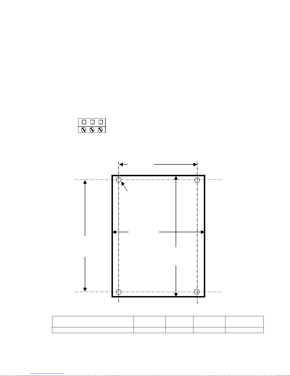
4-7. Receiver Unit Cabinet Mounting.
See next page Figure 4-2. Receiver Mounting
Details. Allow room in mounting the receiver for
the door to swing open
Mount receiver unit cabinet securely to mounting
surface. Actual cabinet mounting dimensions are
shown on next page Figure 4-2. Receiver
Mounting Details.
4-8. Receiver Installation.
NOTE
CONNECTING OUTPUTS TO DRIVES.
MOV’S (TRANSIENT PROTECTORS) ARE
ON ALL THE OUTPUT RELAYS TO
PROTECT THE RELAYS FROM POWER
SURGES. MOV’S ALLOW A SMALL
LEAKAGE CURRENT THAT CAN AFFECT
SOME HIGH IMPEDANCE CIRCUITS.
WHEN CONNECTING OUTPUT RELAYS TO
DRIVES, IT MAY BE REQUIRED TO
REMOVE THE MOV TO PREVENT THE
LEAKAGE CURRENT THROUGH THE MOV
FROM HOLDING IN THE DRIVE. SEE
FIGURE 8-1. RECEIVER LAYOUT FOR THE
LOCATION OF THE MOV'S. THE MOV’S
ARE NEXT TO THE RELAYS THEY
PROTECT. THE MOV’S CAN BE CUT OUT
OF THE CIRCUIT WITH A WIRE CUTTER.
REMEMBER TO DO THIS WITH ALL
POWER OFF ON THE CRANE AND ALL
ASSOCIATED CONTROLS.
1. Normally it should not be necessary to
set the Access Codes, they are preset. If
special field programming is needed.
Power the unit up on the bench and preprogram the unit for any special crane
configurations or other parameters, if
desired, see Section 7 - Programming
for details. The unit can be reprogrammed after it is installed also.
2. Position the receiver. Locate as far as
possible from exposed trolley wire and
sources of electromagnetic or radiated
noise. Cabinet mounting dimensions
and mounting template is on next page
see Figure 4-2. Receiver Mounting
Details. Antenna should be kept as clear
as possible of any metal object.
3. Mount the receiver. The four deep
mounting holes in corners of the
receiver use quantity four #10-24
combo drive round head screws 1.5 “ in
length, four #10 lock washers and four
#10-24 hex nuts to mount. Lock
washers should be used in front of hex
nuts.
4. Wire the unit using the appropriate
electrical drawings for the specific
transmitter and crane orientation
selected, see Section 6 - Wiring. If you
need to remove the main board (4
screws) the antenna unplugs from the
RF Receiver, be sure to dress the
antenna cable on the RF Receiver when
reinstalling the antenna cable.
5. Wire the power to J1 input power
connector. The connections are Ground
(GND), Neutral (N) and 115 VAC 60
Hz (115V).
Connections.
See Figure 4-1. Input Power
11
Telemotive TR12 inteleSmart Receiver Instruction Manual – 03/01/07
Section 4 – Installation (continued)
m
6. Wiring of the system should now be
complete. Install antenna.
7. Turn switch SW2 OFF (MR relay
control) and SW1 ON (main power
switch). Stand clear of the crane and
apply AC power to receiver unit. Check
to see if at least the three green LEDs
DS1, DS2 and DS3 are ON, as well the
red RF Receiver ON LED (other LEDs
may be ON also). If none are lit check
AC power and power switch SW1. See
Figure 8-1. Receiver Layout for switch
and LED locations.
Figure 4-1. Input Power Connections.
1
120V N GRN
J1
11.02”
279.9 mm
7.09”
180 m
.30” DIA.
7.5 mm
hole 4 places
7.87”
200 mm
WHEN FIRST APPLING POWER TO THE
UNIT YOU MUST WAIT 10 SECONDS FOR
THE RECEIVER TO GO THROUGH THE
PROGRAMMING MODE.
8. Wait 10 seconds and turn the
transmitter ON. Check to see if the red
LEDs DS30 and DS32 are now ON. At
this point the MR relay is disabled; the
functions of the transmitter can be
checked by noting the turning ON of the
appropriate red LEDs next to the
control relays (K1-K12). After checking
out the functions, turn switch SW2 ON
to enable the MR relay (red LED DS31
should now turn ON), check function
and direction by jogging each motion.
Installation should now be complete.
9. If there are any problems see Section 8 Servicing.
11.81”
300 mm
NOTE
Drawing not to scale.
Overall Cabinet Depth With door
closed inches
Cabinet 5.26 13
With door
closed mm
3.60 12.12 307.98
With door
open inches
With door open
mm
Figure 4-2. Receiver Mounting Details
Telemotive TR12 inteleSmart Receiver Instruction Manual – 03/01/07
12

Section 5
See Appropriate Transmitter Manual
13
Telemotive TR12 inteleSmart Receiver Instruction Manual – 03/01/07

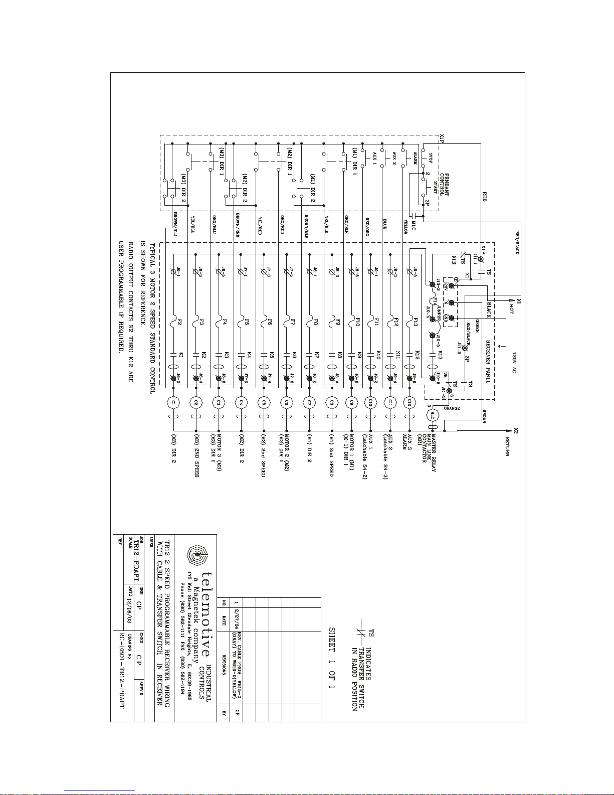
Section 6 - Wiring
6-1. Wiring Diagrams.
The system comes pre-programmed; the
following pages in this section have individual
wiring diagrams for different crane
configurations. Find the appropriate wiring
diagram and if necessary program the receiver
and transmitter switch settings shown for the
appropriate diagram. Terminal designators are
marked on the wiring diagram corresponding to
designators found on the Receiver Board. For
terminal locations see Figure 8-1. Receiver
Layout. After selecting the appropriate motors
for each function remember to place the
appropriate label on your transmitter for
describing the appropriate command.
Typically in the following wiring diagrams, the
Hoist is shown as Motor 1, Trolley as Motor 2
and Bridge is shown as Motor 3. Make sure the
transmitter is labeled with the correct functions.
Stick on or movable button labels are provided
with the transmitter for proper labeling.
6-2. Installation.
Follow the procedure in Section 4 - Installation
for installing the receiver.
6-3. Alarms And Horns.
Make sure that the installation includes the
proper alarms, horns, indicator lights and their
associated controls as required by local and
governmental regulations.
6-4. Relay Sequencing.
The Diagrams in this section show actual relay
sequencing. Typically the directional stays in
when the second and third speed is actuated.
6-5. Alarm After ESTOP.
When connecting output relays to drives, it may
be required to remove the MOV to prevent the
leakage current through the MOV from holding
in the drive. See Figure 8-1. Receiver Layout for
the location of the MOV's. The MOV’s are next
to the relays they protect. The MOV’s can be cut
out of the circuit with a wire cutter. Remember
to do this with ALL power OFF on the crane and
all associated controls.
6-7. Single-Speed Transmitter Wiring.
For a Single-Speed Transmitter the only wiring
configuration is the diagram in Section 6 Wiring. Table 1, Single-Speed Standard
Configuration Hoist, Trolley and Bridge.
6-8. 2-Speed and 3-Speed telePendant
operation.
A 3-Speed telePendant will work on a 2-Speed
receiver; the 3
the motion buttons will not activate any
functions or speed changes. To use a 3-Speed
telePendant on a 2-Speed receiver the
particular transmitter Bank to be used must have
matching frequency, Access Codes and its Tx
Type” set to “3 SPD telePendant”. For the 3Speed telePendant transmitter there are no
configuration switches to set, the default for the
configuration switches is all OFF. The number of
Motors must be selected.
6-9. Commons.
Each receiver relay output (normally open) is
independent (floating) both input and output.
Relay commons (Hot) are not wired together on
the Receiver Board nor connected to the input
power. Relay common wiring must be provided.
This is to give total flexibility. Different motors
and/or functions can use different phases or
independent (even DC) power sources.
rd
speed position (switch detent) on
This is only for wiring configurations where the
Aux 3 (relay K12, output J8-6) is being used for
the Alarm function, placing a jumper on JU1 on
the Receiver Board will allow the alarm to
function after an ESTOP command. See Figure
8-1. Receiver Layout for jumper location.
6-6. Connecting Outputs To Drives.
MOV’s (transient protectors) are on all the
output relays to protect the relays from power
surges. MOV’s allow a small leakage current
that can affect some high impedance circuits.
14
6-10. Power or Hot routing.
The Diagrams in this Section show independent
power “HOT” routed to each relay. An alternate
way of routing power is to route all power to
each function from the MR (Master Relay) relay.
This wiring can only be used if the total current
does not exceed the MR relay ratings.
Telemotive TR12 inteleSmart Receiver Instruction Manual – 03/01/07

Section 6 - Wiring (Continued)
H
B
H
*
B
6-11. Legend.
The following is the legend for the wiring diagrams below:
#
An input with the terminal
number # matching the connector in the receiver.
Auxiliary
Controls
AUX 1
AUX 2
AUX 3
ON/
OFF
K#
Matching relay contacts
in radio receiver panel
by number.
ON/OFF & Low Battery Indicators
Figure 6-1. Legend.
Motor 1
Dir 1
Dir 2
Motor 2
Dir 1
Dir 2
Motor 3
Dir 1
Dir 2
OIST*
TROLLE
RIDGE
ON/
OFF
Y
A B
AUX 1
AUX 2
AUX 3
AUX 4
AUX 5
AUX 6
Aux
Controls
#
An output with the terminal
number # matching the connector in the receiver.
iliary
C#
Customer supplied
contactor coil with arc
suppressor in parallel.
Motor 1
Dir 1
Dir 2
Motor 2
Dir 1
Dir 2
Motor 3
Dir 1
OIST*
TROLLE
RIDGE*
Dir 2
Y
TX12M-2
A B
Optional
4th Motor or Select Indicators
2-Speed telePilot
*
NOTE: Hoist, Trolley and Bridge are listed here as traditional configurations,
the installer may choose to define the motors differently.
Figure 6-2. telePilot and telePendant, Output Controls
15
E-STOP
E-STOP
Programmable
Motor Control and Select Indicators
2-Speed telePendant
Telemotive TR12 inteleSmart Receiver Instruction Manual – 03/01/07
Wiring for Internal Transfer Switch using Optional Pigtail.
Section 6 - Wiring (continued)
Telemotive TR12 inteleSmart Receiver Instruction Manual – 03/01/07
16
 Loading...