

Magnetek inteleSmart2 User Manual

inteleSmart2 RECEIVER
Engineered
AC/DC Relay Receiver
Part Number: 198-80102-0002 R1
June 2016
© 2016 Magnetek

Your New Radio Receiver
Thank you for your purchase of Magnetek’s inteleSmart2 Receiver Radio Remote Equipment Control.
Magnetek has set a whole new standard in radio-remote performance, depen dability, and value with this
line of modular receivers.
If your product ever needs modification or service, please contact one of our representatives at the
following locations:
U.S. Service Information
For questions regarding service or technical information contact:
1.866.MAG.SERV
1.866.624.7378
International Service:
+1.262.783.3500
Magnetek, Inc.
N49 W13650 Campbell Drive
Menomonee Falls, WI 53051
Telephone: +1.800.288.8178
Website: www.magnetek.com
E-mail: mhcustomerservice@magnetek.com
Fax Numbers:
Main: +1.800.298.3503
Sales: +1.262.783.3510
Service: +1.262.783.3508
Canada Service Information:
161 Orenda Road
Unit 1
Brampton, Ontario
L6W 1W3 Canada
Phone: +1.800.792.7253
Fax: +1.905.828.5707
©2016 MAGNETEK
All rights reserved. This notice applies to all copyrighted materials included with this produ ct, including,
but not limited to, this manual and software embodied within the product. This manual is intended for the
sole use of the person(s) to whom it was provided, and any unauthorized distribution of the manual or
dispersal of its contents is strictly forbidden. This manual may not be reproduced in whole or in part by
any means whatsoever without the expressed written permission of MAGNETEK.
EU Market Contact:
Brian Preston
Magnetek (UK) Ltd.
Unit 3 Bedford Business Centre, Mile Road
Bedford, MK42 9TW UK
Phone: +44.1234.349191
Fax: +44.1234.268955

TABLE OF CONTENTS
1. PRODUCT MANUAL SAFETY INFORMATION ................................................................................ 5
2. CRITICAL INSTALLATION CONSIDERATIONS ............................................................................... 7
2.1 GENERAL ..................................................................................................................................... 7
2.2 PERSONS AUTHORIZED TO OPERATE RADIO CONTROLLED EQUIPMENT ....................... 7
2.3 SAFEY INFORMATION & RECOMMENDED TRAINING FOR OPERATORS ............................ 7
2.4 PRE-OPERATION TEST .............................................................................................................. 9
2.5 CRANE-SPECIFIC DEVICE WARNINGS .................................................................................... 9
3. INTELESMART2 INSTALLATION ................................................................................................... 11
3.1 PRE-INSTALLATION .................................................................................................................. 11
3.2 RECEIVER UNIT MOUNTING LOCATION CONSIDERATIONS ............................................... 11
3.3 ANTENNA MOUNTING CONSIDERATIONS ............................................................................. 11
3.4 LINE INPUT CONSIDERATIONS ............................................................................................... 12
3.5 WIRING CONSIDERATION ........................................................................................................ 12
3.6 RECEIVER/EQUIPMENT INTERFACE CONSIDERATIONS .................................................... 13
3.7 RECEIVER UNIT ENCLOSURE MOUNTING ............................................................................ 13
3.8 RECEIVER INSTALLATION ....................................................................................................... 13
3.9 MECHANICAL DRAWINGS ........................................................................................................ 14
4. WIRING ............................................................................................................................................ 16
4.1 ALARMS AND HORNS ............................................................................................................... 16
4.2 POWER ....................................................................................................................................... 16
4.2.1 DC Power ............................................................................................................................ 16
4.2.2 AC Power ............................................................................................................................ 16
4.3 COMMONS ................................................................................................................................. 17
4.4 POWER OR HOT ROUTING ...................................................................................................... 17
4.5 MACHINE STOP (MC) RELAYS ................................................................................................. 17
4.6 WIRING DIAGRAMS ................................................................................................................... 17
4.6.1 Wiring Isolation Options ...................................................................................................... 19
4.7 CONNECTING OUTPUTS TO DRIVES ..................................................................................... 19
4.8 ANALOG INPUT.......................................................................................................................... 19
4.9 DIGITAL INPUTS ........................................................................................................................ 20
4.10 EXPANSION MODULES ............................................................................................................ 20
5. NORMAL OPERATION .................................................................................................................... 21
5.1 INITIALIZATION .......................................................................................................................... 21
6. INTELESMART2 EXPANSION MODULE TYPES ........................................................................... 23
6.1 RELAY EXPANSION MODULE .................................................................................................. 23
7. PROGRAMMING WITH RCP .......................................................................................................... 26
7.1 ACCESS CODES ........................................................................................................................ 26
7.2 CHANGING ACCESS CODES ................................................................................................... 26
7.3 CONNECTING THE INTELESMART2 TO A COMPUTER ........................................................ 27
7.4 PROGRAMMING WITH RCP ..................................................................................................... 27
7.4.1 inteleSmart2 Configuration Page ........................................................................................ 30
7.4.2 Programming Page ............................................................................................................. 34
7.4.3 FDP Page ............................................................................................................................ 35
7.4.4 Saving, Downloading, And Reading The Programs And Other RCP Software Functions . 36
8. RECEIVER CHANNEL CONFIGURATION SETTINGS .................................................................. 38
8.1 FCC STATEMENTS .................................................................................................................... 38
8.2 433MHz CHANNEL SET ............................................................................................................. 39

8.3 433 MHz Telemotive Legacy Channel Set .................................................................................. 40
8.4 900MHz CHANNEL SET ............................................................................................................. 41
8.5 419MHz CHANNEL SET ............................................................................................................. 42
8.6 2.4 GHz: FHSS ............................................................................................................................ 43
9. TROUBLESHOOTING ..................................................................................................................... 44
9.1 TROUBLESHOOTING TABLE .................................................................................................... 45
9.2 RECEIVER SPECIFICATIONS ................................................................................................... 48
9.3 ASSEMBLY AND REPLACEMENT PARTS ............................................................................... 48
10. NOTES ............................................................................................................................................. 49

1. PRODUCT MANUAL SAFETY INFORMATION
Magnetek, Inc. (Magnetek) offers a broad range of radio remote control products, control products and
adjustable frequency drives, and industrial braking systems for overhead material handling applications.
This manual has been prepared by Magnetek to provide information and recommendations for the
installation, use, operation and service of Magnetek’s material handling products and systems (Magnetek
Products). Anyone who uses, operates, maintains, services, installs or owns Magnetek Products should
know, understand and follow our instructions and safety recommendations in this manual for Magnetek
Products.
The recommendations in this manual do not take precedence over any of the following requirements
relating to cranes, hoists and lifting devices:
Instructions, manuals, and safety warnings of the manufacturers of the equipment where the
radio system is used,
Plant safety rules and procedures of the employers and the owners of facilities where the
Magnetek Products are being used,
Regulations issued by the Occupational Health and Safety Administration (OSHA),
Applicable local, state or federal codes, ordinances, standards and requirements, or
Safety standards and practices for the overhead material handling industry.
This manual does not include or address the specific instru ctions and safety warnings of these
manufacturers or any of the other requirements listed above. It is the responsibility of the owners, users
and operators of the Magnetek Products to know, understand and follow all of these requirements. It is
the responsibility of the owner of the Magnetek Products to make its employees aware of all of the above
listed requirements and to make certain that all operators are properly trained. No one should use
Magnetek Products prior to becoming familiar with and being trained in these requirements.
WARRANTY INFORMATION
FOR INFORMATION ON MAGNETEK’S PRODUCT WARRANTIES BY PRODUCT TYPE, PLEASE VISIT
WWW.MAGNETEK.COM.
inteleSmart2 Instruction Manual
June 2016
Page 5 of 49
WARNINGS and CAUTIONS
Throughout this document WARNING and CAUTION statements have been deliberately plac ed to
highlight items critical to the protection of personnel and equipment.
WARNING – A warning highlights an essential operating or maintenance procedure, practice, e tc.
which if not strictly observed, could result in injury or death of personnel, or long term physical
hazards. Warnings are highlighted as shown below:
WARNING
CAUTION – A caution highlights an essential operating or maintenance procedure, pr actice, etc.
which if not strictly observed, could result in damage to, or destruction of equipment, or loss of
functional effectiveness. Cautions are highlighted as shown below:
CAUTION
WARNINGS and CAUTIONS SHOULD NEVER BE DISREGARDED
The safety rules in this section are not intended to replace any rules or regulations of any applicabl e local,
state, or federal governing organizations. Always follow your local lockout and tagout procedure when
maintaining any radio equipment. The following information is intended to be used in conjunction with
other rules or regulations already in existence. It is important to read all of the safety information
contained in this section before installing or operating the Radio Control System.
inteleSmart2 Instruction Manual
June 2016
Page 6 of 49

2. CRITICAL INSTALLATION CONSIDERATIONS
WARNING
PRIOR TO INSTALLATION AND OPERATION OF THIS EQUIPMENT, READ AND DEVELOP AN
UNDERSTANDING OF THE CONTENTS OF THIS MANUAL AND THE OPERATION MANUAL OF THE
EQUIPMENT OR DEVICE TO WHICH THIS EQUIPMENT WILL BE INTERFACED. FAILURE TO FOLLOW THIS
WARNING COULD RESULT IN SERIOUS INJURY OR DEATH AND DAMAGE TO EQUIPMENT.
FOLLOW YOUR LOCAL LOCKOUT TAGOUT PROCEDURE BEFORE MAINTAINING ANY REMOTE
CONTROLLED EQUIPMENT. ALWAYS REMOVE ALL ELECTRICAL POWER FROM THE EQUIPMENT BEFORE
ATTEMPTING ANY INSTALLATION PROCEDURES. DE-ENERGIZE AND TAGOUT ALL SOURCES OF
ELECTRICAL POWER BEFORE TOUCH-TESTING ANY EQUIPMENT. FAILURE TO FOLLOW THIS WARNING
COULD RESULT IN SERIOUS INJURY OR DEATH AND DAMAGE TO EQUIPMENT.
AFTER INSTALLATION BE SURE TO VERIFY THAT THE TRANSMITTER IS NOT INTERFERING WITH OTHER
EQUIPMENT IN THE AREA. ALSO VERIFY THAT OTHER EQUIPMENT IS NOT INTERFERING WITH THE
TRANSMITTER AND ITS ASSOCIATED EQUIPMENT. FAILURE TO FOLLOW THESE WARNINGS COULD
RESULT IN SERIOUS INJURY OR DEATH AND DAMAGE TO EQUIPMENT.
2.1 GENERAL
Radio controlled equipment operates in several directions. Quite frequently, the equipment is operated i n areas
where people are working in close proximity to the equipment. The operator must exercise extreme caution at all
times. Workers must constantly be alert to avoid accidents. The following recommendations have been included to
indicate how careful and thoughtful actions may prevent injuries, damage to equipment, or even save a life.
2.2 PERSONS AUTHORIZED TO OPERATE RADIO CONTROLLED
EQUIPMENT
Only properly trained persons designated by management should be permitted to operate radio controlled equipment.
Radio controlled equipment should not be operated by any person who cannot read or understand signs, notices and
operating instructions that pertain to the equipment.
Radio controlled equipment should not be operated by any person with insufficient eyesight or hearing or by any
person who may be suffering from a disorder or illness, is taking any medication that may cause loss of equipment
control, or is under the influence of alcohol or drugs.
2.3 SAFEY INFORMATION & RECOMMENDED TRAINING FOR
OPERATORS
Anyone being trained to operate radio controlled equipment should possess as a minimum the following knowledge
and skills before using the radio controlled equipment.
The operator should:
have knowledge of hazards pertaining to equipment operation
have knowledge of safety rules for radio controlled equipment
inteleSmart2 Instruction Manual
June 2016
Page 7 of 49
have the ability to judge distance of moving objects
know how to properly test prior to operation
be trained in the safe operation of the radio transmitter as it pertains to the equipment being operated
have knowledge of the use of equipment warning lights and alarms
have knowledge of the proper storage space for a radio control transmitter when not in use
be trained in transferring a radio control transmitter to another person
be trained how and when to report unsafe or unusual operating conditions
test the transmitter emergency stop and all warning devices prior to operation; testing should be done on
each shift, without a load
be thoroughly trained and knowledgeable in proper and safe operation of the equipment that utilizes the
radio control
know how to keep the operator and other people clear of hazardous areas
know and follow the local lockout and tagout procedures when servicing radio controlled equipment
know and follow all applicable operating and maintenance manuals, safety procedures, regulatory
requirements, and industry standards and codes
The operator shall not:
operate the equipment if the direction of travel or function engaged does not agree with what is indicated on
the controller
operate any damaged or malfunctioning equipment
change any settings or controls without authorization and proper training
remove or obscure any warning or safety labels or tags
leave power on the radio controlled equipment when the equipment is not in operation
operate any equipment using a damaged controller because the unit may be unsafe
operate manual motions with other than manual power
operate radio controlled equipment when low battery indicator is on
WARNING
THE OPERATOR SHOULD NOT ATTEMPT TO REPAIR ANY RADIO CONTROLLER. IF ANY PRODUCT
PERFORMANCE OR SAFETY CONCERNS ARE OBSERVED, THE EQUIPMENT SHOULD IMMEDIATELY
BE TAKEN OUT OF SERVICE AND BE REPORTED TO THE SUPERVISOR. DAMAGED AND INOPERABLE
RADIO CONTROLLER EQUIPMENT SHOULD BE RETURNED TO MAGNETEK FOR EVALUATION AND
REPAIR. FAILURE TO FOLLOW THIS WARNING COULD RESULT IN SERIOUS INJURY OR DEATH AND
DAMAGE TO EQUIPMENT.
inteleSmart2 Instruction Manual
June 2016
Page 8 of 49
2.4 PRE-OPERATION TEST
At the start of each work shift, or when a new operator takes control of the equipment, operators should do,
as a minimum, the following steps before making lifts with any equipment:
Test all warning devices.
Test all functions.
Test the transmitter machine stop.
2.5 CRANE-SPECIFIC DEVICE WARNINGS
WARNING
ALL EQUIPMENT MUST HAVE A MAINLINE CONTACTOR INSTALLED AND ALL TRACKED CRANES, HOISTS,
LIFTING DEVICES AND SIMILAR EQUIPMENT MUST HAVE A BRAKE INSTALLED. FAILURE TO FOLLOW THIS
WARNING COULD RESULT IN SERIOUS INJURY OR DEATH AND DAMAGE TO EQUIPMENT.
AN AUDIBLE AND/OR VISUAL WARNING MEANS MUST BE PROVIDED ON ALL REMOTE CONTROLLED
EQUIPMENT AS REQUIRED BY CODE, REGULATION, OR INDUSTRY STANDARD. THESE AUDIBLE AND/OR
VISUAL WARNING DEVICES MUST MEET ALL GOVERNMENTAL REQUIREMENTS. FAILURE TO FOLLOW
THIS WARNING COULD RESULT IN SERIOUS INJURY OR DEATH AND DAMAGE TO EQUIPMENT.
THE DIRECT OUTPUTS OF THIS PRODUCT ARE NOT DESIGNED TO INTERFACE DIRECTLY TO TWO STATE
SAFETY CRITICAL MAINTAINED FUNCTIONS, I.E., MAGNETS, VACUUM LIFTS, PUMPS, EMERGENCY
EQUIPMENT, ETC. A MECHANICALLY LOCKING INTERMEDIATE RELAY SYSTEM WITH SEPARATE POWER
CONSIDERATIONS MUST BE PROVIDED. FAILURE TO FOLLOW THIS WARNING COULD RESULT IN
SERIOUS INJURY OR DEATH OR DAMAGE TO EQUIPMENT.
Cranes, hoists, lifting devices and other material handling equipment can be large, and operate at high speeds.
The operator should:
continuously watch and monitor status of lifted loads
know and follow cable and hook inspection procedures
The operator shall not:
lift or move more than the rated load
use the crane, hoist or lifting device to lift, support or transport people
lift or carry any loads over people
operate the crane, hoist or lifting device unless all persons, including the operator, are and remain clear of
the supported load and any potential pinch points
operate a crane, hoist or lifting device when the device is not centered over the load
inteleSmart2 Instruction Manual
June 2016
Page 9 of 49

operate a crane, hoist or lifting device if the chain or wire rope is not seated properly in the sprockets, drum
or sheave
leave any load unattended while lifted
inteleSmart2 Instruction Manual
June 2016
Page 10 of 49
3. INTELESMART2 INSTALLATION
WARNING
BEFORE OPERATING THE RECEIVER FAMILIARIZE YOURSELF WITH ALL SAFETY INFORMATION IN
THIS MANUAL, APPROPRIATE MANUAL SUPPLEMENT S AND ANY OTHER LOCAL, STATE, OR FEDERAL
RULES OR REGULATIONS ALREADY IN EXISTENCE. FAILURE TO FOLLOW THIS WARNING COULD
RESULT IN SERIOUS INJURY OR DEATH AND DAMAGE TO EQUIPMENT.
3.1 PRE-INSTALLATION
1. Transmitter and receiver access code, channel, and project ID must match before the system will
communicate.
2. Be aware of other radio channels in the surrounding area - set your system to a unique channel.
3. Make sure that your equipment is working properly in manual mode prior to system installation.
4. Make sure the power to the receiver is the correct voltage.
5. Disconnect equipment power prior to system installation.
3.2 RECEIVER UNIT MOUNTING LOCATION CONSIDERATIONS
Ensure the mounting location is as far as possible from exposed trolley wires and sources of
electromagnetic or radiated noise as possible.
The receiver enclosure is approximately 20cm (8 in) wide by 30cm (12 in) high by 13cm (5.1 in) deep.
The mounting surface must be smooth and continuous. Mounting the cabinet on uneven surfaces could
cause warping or stress internal components.
If possible, avoid installing receiver unit to a surface where high vibration or shock is present. If this
cannot be avoided, use appropriate shock mounts.
3.3 ANTENNA MOUNTING CONSIDERATIONS
It is best to mount the antenna so that it is visible to the operator. This is usually accomplished by
mounting the antenna under the crane. However, it is not recommended to point the antenna straight
down, as this will cause a “dead” spot directly under the antenna. The antenna should be mounted at a
45 degree angle perpendicular to the operator. Always try to avoid power sources, motors, drives,
brakes, etc., when installing the antenna. If necessary, Magnetek offers an external antenna kit.
inteleSmart2 Instruction Manual
June 2016
Page 11 of 49
3.4 LINE INPUT CONSIDERATIONS
WARNING
THE UNIT MUST BE WIRED TO THE CORRECT VOLTAGE, AND BE CONNECTED TO THE CORRECT
TERMINAL AS REQUIRED BY THE ACTUAL LINE VOLTAGE. FAILURE TO FOLLOW THIS WARNING
COULD RESULT IN SERIOUS INJURY OR DEATH AND DAMAGE T O EQUIPMENT.
Refer to Section 4.2 for information on how to configure the unit’s input power.
NOTE: The receiver unit should not be connected to lines containing excessive power up transients or
continuous commutator noise. A line conditioner may be necessary in some installations.
3.5 WIRING CONSIDERATION
1. Read this manual before installation.
2. Please observe appropriate local and National Electrical Codes when wiring electrical devices.
3. Do not connect or disconnect wiring, or perform circuit checks while the power is turned on.
4. The motor wiring and the power wiring should also be in separate metal conduits.
5. Low voltage wires shall be wired with proper low voltage class wiring procedures.
6. Control wiring as well as antenna wiring shall be in separate conduit and shall be kept as short as
possible.
7. All terminals shall be tightened to specified terminal torque 4.4 IN-LBS (.5 N·m), unless otherwise
specified.
8. Remove excess metal screws, metal filings, and wire clippings from inside of u nit.
9. Inspect to make sure no exposed wire has contact with any other wiring or terminals.
10. RC type suppressors are strongly recommended on all contactors.
inteleSmart2 Instruction Manual
June 2016
Page 12 of 49

3.6 RECEIVER/EQUIPMENT INTERFACE CONSIDERATIONS
All output relay contacts are rated for 10 Amps 277VAC/30VDC, 1 HP 240VAC for maximum life and
surge protection, and protected with MOVs. Connection to equipment or contactors with higher voltage or
current requirements will require intermediate relays.
Relay outputs K1-K11 are normally open, single pole single throw (SPST) relays. Relay output K12 is a
normally open, dual pole single throw (DPST) relay. Relay outputs K13-K14 are Form C “flip-flop” relays
(flip-flop relays contain both normally open and normally closed outputs). Since a relay closure is only
active while the transmitter unit key is pressed and held, devices such as lights or lifting magnets must
use a mechanical auxiliary latching relay.
3.7 RECEIVER UNIT ENCLOSURE MOUNTING
When mounting the receiver, make sure to allow room for the door to swing open. Mount the receiver
unit cabinet securely to the mounting surface. Actual cabinet mounting dimensions are shown in Section
3.9.
3.8 RECEIVER INSTALLATION
1. Be sure to mount the receiver antenna in direct line-of-sight of the operator and free from all
obstructions.
2. Do not mount the receiver near high levels of electrical noise, such as unshielded variable frequency
drives, as they may cause minor interference. When mounting the inteleSmart2 near unshielded
variable frequency drives Magnetek typically recommends that the inteleSmart2 and all antenna cable
routing be mounted a minimum of 24 inches from all unshielded variable frequency drives and cabl es.
3. Allow adequate room for mounting the receiver. Be sure to allow a minimum of 12.7cm (5 in) between
the connector and nearest surface to allow for cable harness connections.
4. For best reception, and to help protect connectors from moisture and water damage, mount the
receiver such that the external antenna connector is pointing straight up and the connections come
out the bottom of the unit. Placement of the antenna needs to be in a location such that there is line
of sight between the antenna and the transmitter. Refer to Section 3.3 for additional antenna
mounting considerations.
5. If obstructions cannot be cleared, or if the unit must be mounted inside of a metal enclosure, the
remote antenna should be used.
6. Do not enclose the antenna in steel. If the receiver is mounted within an enclosure, an external
antenna MUST be used. For the best reception, keep all metal objects away from the antenna.
Consult the factory for more information regarding your application.
7. The supply power to the inteleSmart2 system must have a master disconnect and should be fused.
8. It should not be necessary to set the Access Code or channel, as they are preset. If special field
programming is needed, power the unit up on the bench and program the unit for any special
configurations or other parameters (see Section 7 for details). The unit can be re-programmed after it
is installed if necessary.
9. Position the receiver; make sure to locate it as far as possible from exposed trolley wire and sources
of electromagnetic or radiated noise. Enclosure mounting dimensions and mounting can be found in
Figure 1.
10. Mount the receiver. Refer to Section 3.9 for further information regarding mounting.
11. Wire the unit using the electrical drawings shown in Section Error! Reference source not found..
12. Wire the power input for the input power type as described in Section 4.2.
inteleSmart2 Instruction Manual
June 2016
Page 13 of 49
13. Wiring of the system should now be complete. Install antenna.
14. If there are any problems, refer to Section 9.
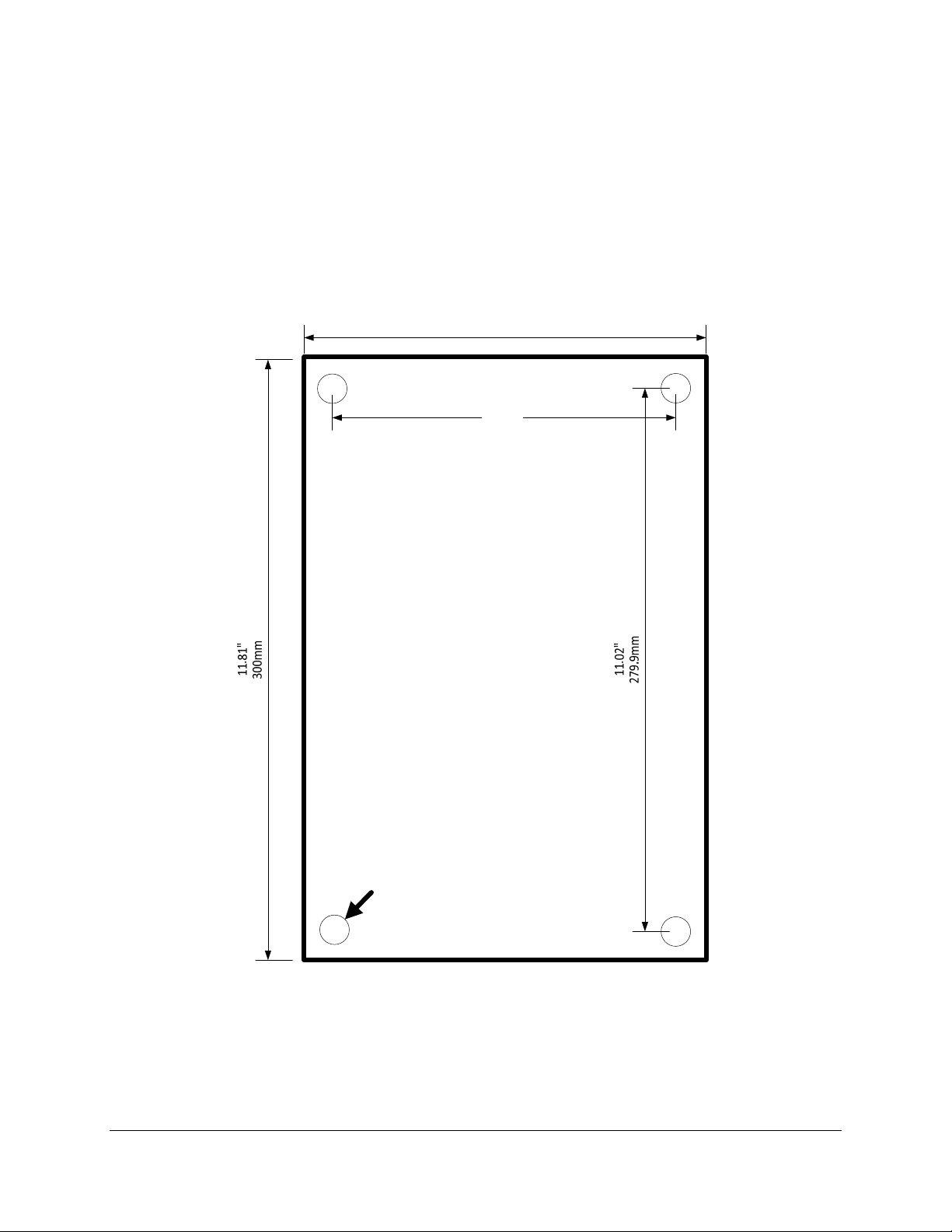
3.9 MECHANICAL DRAWINGS
The receiver housing provides four mounting holes. The mounting hardware should consist of M5 (#10 -
24) combo drive round head screws that are 40mm (1.5 in) in length, four M5 (# 10) lock washers, and
four M5 (#10-24) hex nuts to mount. Lock washers should be used in front of hex nuts.
7,87"
200mm
7.09"
180mm
NOTE: Figure 1 is not to scale.
.30"DIA.
7.5mm
Hole4places
Figure 1: Housing Mounting
inteleSmart2 Instruction Manual
June 2016
Page 14 of 49
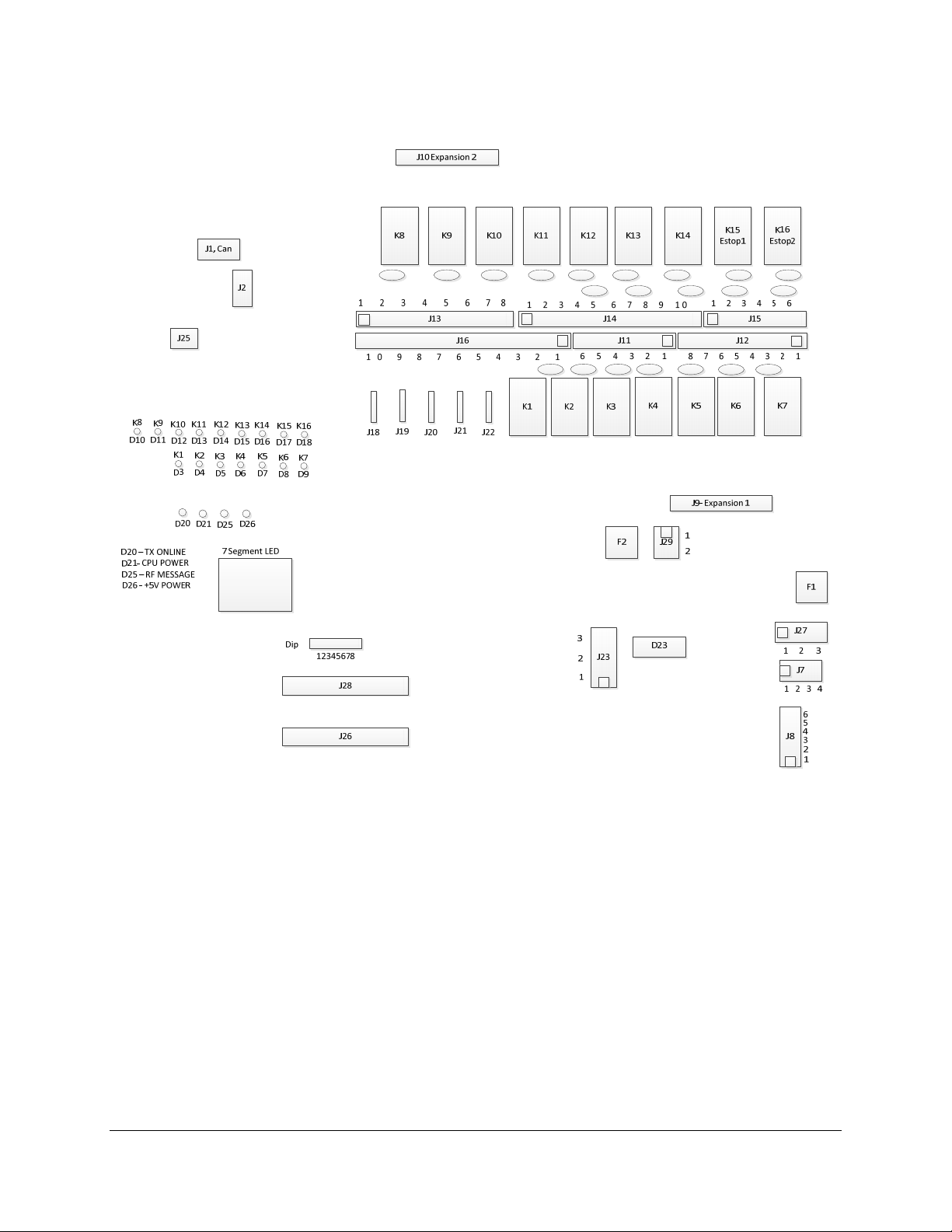
Figure 2 shows the placement of the major components used within the receiver.
Figure 2: Main Board Component Placement
inteleSmart2 Instruction Manual
June 2016
Page 15 of 49
 Loading...