

Magnetek IMPULSE G+ Series 3, IMPULSE VG+ Series 3, IMPULSE G+ Series 4, IMPULSE VG+ Series 4 Product Manual
Product Transition Guide
IMPULSE
®
•G+ & VG+ Series 3 to
Series 4
IMPULSE®•G+ & VG+ Series 4 Transition Guide

Product Transition Guide
IMPULSE
®
•G+ & VG+ Series 4
Page Intentionally Left Blank
IMPULSE®•G+ & VG+ Series 3 to Series 4 Transition Guide August 2011
Page 2 of 54
Magnetek, Inc.

Product Transition Guide
Table of Contents
1.1 Overview ..........................................................................................................................4
1.2 Drive Replacement Checklist ..........................................................................................4
1.3 Ratings Summary ............................................................................................................6
1.4 Digital Operator Comparison ...........................................................................................8
1.5 Terminals .........................................................................................................................9
Main Circuit Terminals ...............................................................................................9
Control Circuit Terminals ..........................................................................................10
1.6 Terminal Size and Wire Gauge Comparison .................................................................12
1.7 Dimensions, Installation Space and Substitution Material ............................................25
Drive Dimension Comparison ..................................................................................25
IMPULSE® G+/VG+ Series 4 Drive Options ............................................................27
1.8 Parameter Cross Reference ..........................................................................................31
IMPULSE®•G+ & VG+ Series 3 to Series 4 Transition Guide August 2011
Page 3 of 54
Magnetek, Inc.
Product Transition Guide
IMPULSE
®
•G+ & VG+ Series 4
1.1 Overview
This purpose of this document is to provide an easy transition from the G+/VG+ Series 3 to the G+/VG+ Series 4.
For the advanced portion, please refer to the G+/VG+ Series 4 Instruction Manual (P/N 144-23910).
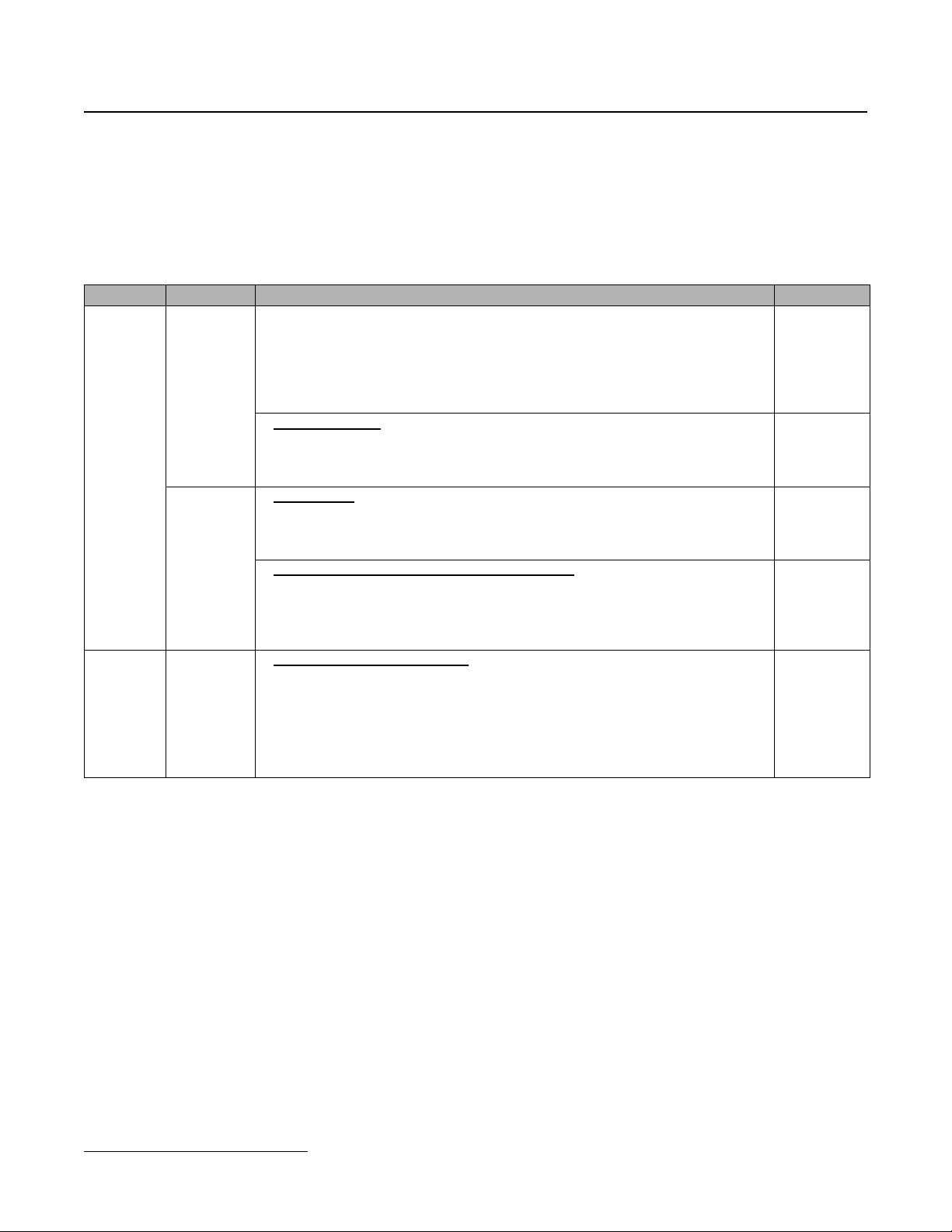
1.2 Drive Replacement Checklist
Item Checkpoints Checked?
• Can the existing mounting holes be used? Check if the new drive dimensions
are different than the current drive.
– Verify that the existing dimensions reference in Section 1.7, “Dimensions,
installation space and substitution material” of this manual compares the
Basic
Hardware
Main and
Control
Terminals
Software Parameter
sizes of the current and new unit. If a mechanical substitution kit is necessary,
it is referenced in Section 1.7.
< Digital operator >
• Was a remote operator connected to the current unit?
– If so, do not attempt to connect the G+ Series 3 remote operator to the G+
Series 4, as they are incompatible.
< Wire Length
• In the replacement drive, the main and control circuit terminals may be mounted
in different positions. Check to ensure all cables are long enough to be
connected to the new unit.
< Main circuit wires and terminal specifications >
• Compare the occupied terminals of the current unit with the new drive’s
terminals (shape, size, etc.), and verify that the wires fit in the new unit’s
terminals, using Section 1.5 “Terminals”, specifically “Control Terminal Sizes
and Wire Sizes” of this document.
< Check the parameter settings
• Read the parameter settings of the current unit and perform a parameter
conversion to the new parameters.
– Use IMPULSE
– Consult Magnetek Service for conversion assistance.
– If there is special software installed or parameters appear that are not
mentioned in this document, contact your Magnetek representative.
>
®
Link for conversion.
>
IMPULSE®•G+ & VG+ Series 3 to Series 4 Transition Guide August 2011
Page 4 of 54
Magnetek, Inc.
Product Transition Guide
IMPULSE
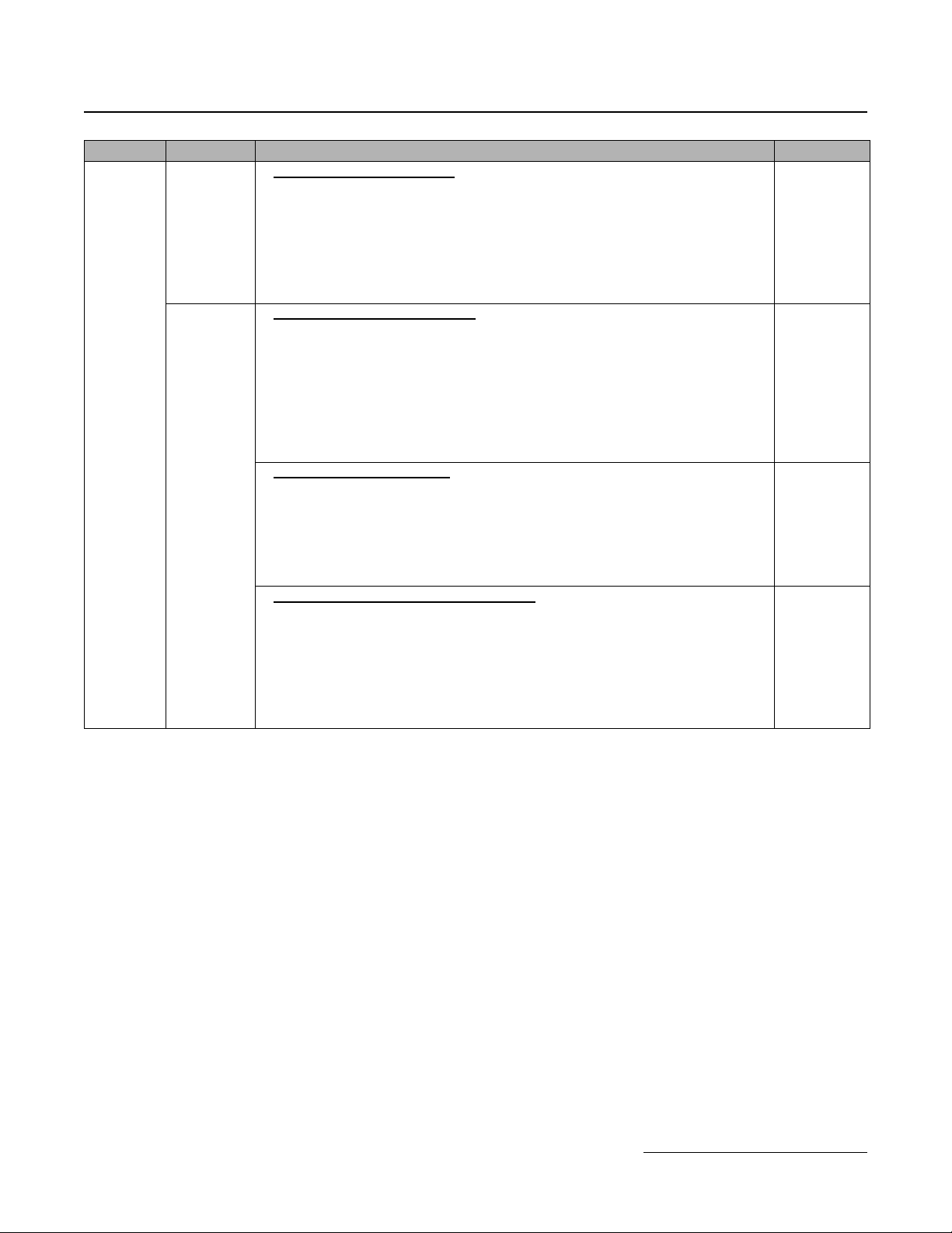
Item Checkpoints Checked?
< Is an option card installed?
• Check if any option card is installed.
– If an option card is installed, get the equivalent option card for the G+ Series
Option
Cards
Options,
Others
Others
• Refer to the instruction manual for questions about installation, parameter settings or detailed parameter/function
descriptions.
4.
– Never attempt to apply G+ Series 3 option cards to the G+ Series 4 unit.
– The option card on the G+ Series 4 may have a different connector on the G+
Series 3. Make sure that the connectors fit into the new option card before
using it.
< Is a braking resistor installed?
• Check if a braking resistor is installed on the current drive.
– Inspect the braking resistor for physical damage or wear before connecting it
to the new drive.
– Inspect the DB wiring for cracking and possible shorts.
– Connect the braking resistor to the equivalent terminals on the new unit.
– The terminals might have a different location in the new drive; check to ensure
that existing wiring is long enough to reach the new terminal location.
– Verify terminal differences.
< Is a braking unit installed?
• Check if a braking unit is used in the current installation.
– Inspect the braking unit for physical damage or wear before connecting it to
the new drive.
– Connect the braking unit to the equivalent terminals on the new unit.
– The terminals might have a different location in the new drive; check to ensure
that existing wiring is long enough to reach the new terminal location.
< Is an AC reactor or DC choke installed?
• Check if an AC reactor or DC choke is used in the current installation.
– Inspect the reactor or choke and wiring for physical damage or wear before
connecting it to the new drive.
– Make sure that the reactor or choke data are appropriate for the replacement
drive.
– The terminals might have a different location in the new drive; check to ensure
that existing wiring is long enough to reach the new terminal location.
>
>
>
>
®
•G+ & VG+ Series 4
IMPULSE®•G+ & VG+ Series 3 to Series 4 Transition Guide August 2011
Page 5 of 54
Magnetek, Inc.
Product Transition Guide
IMPULSE
®
•G+ & VG+ Series 4
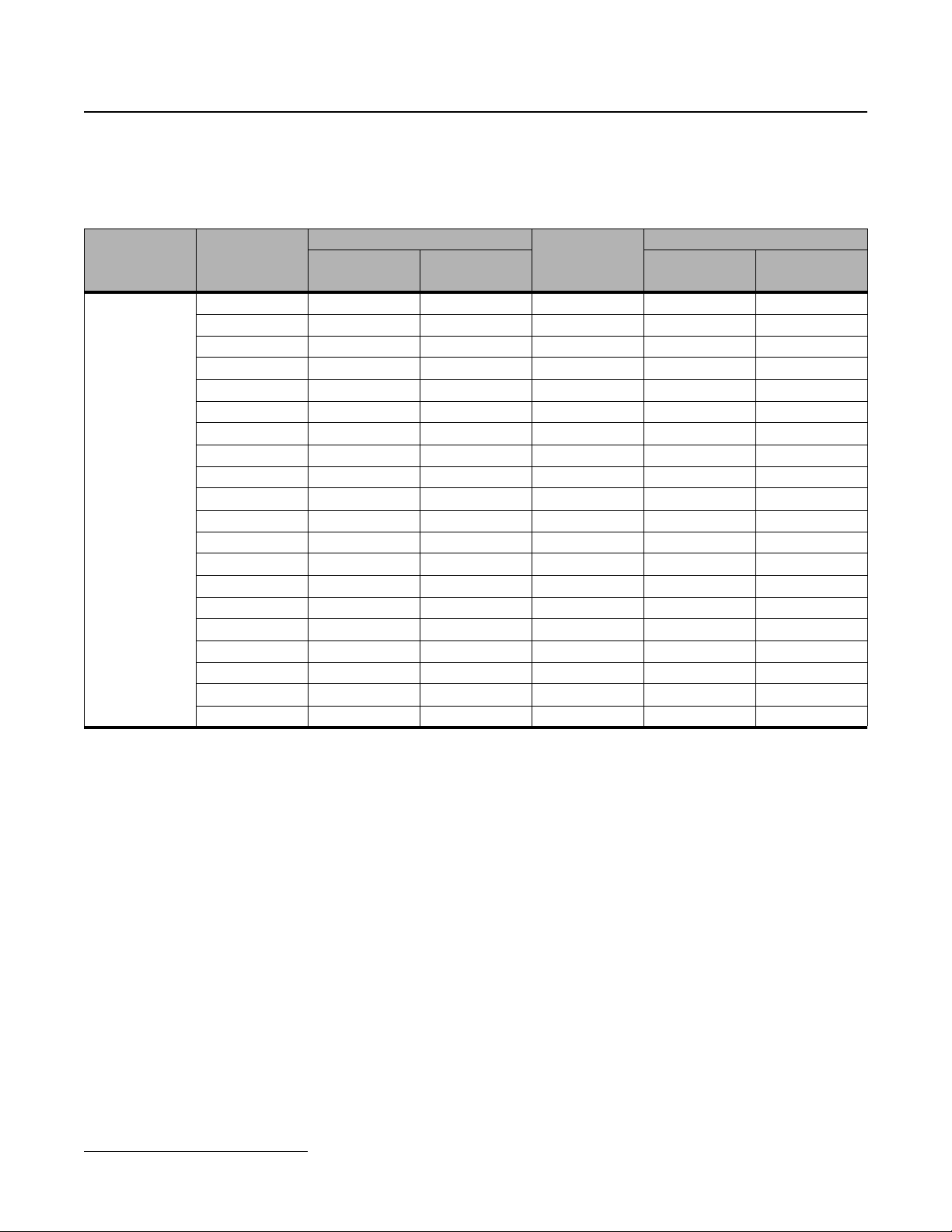
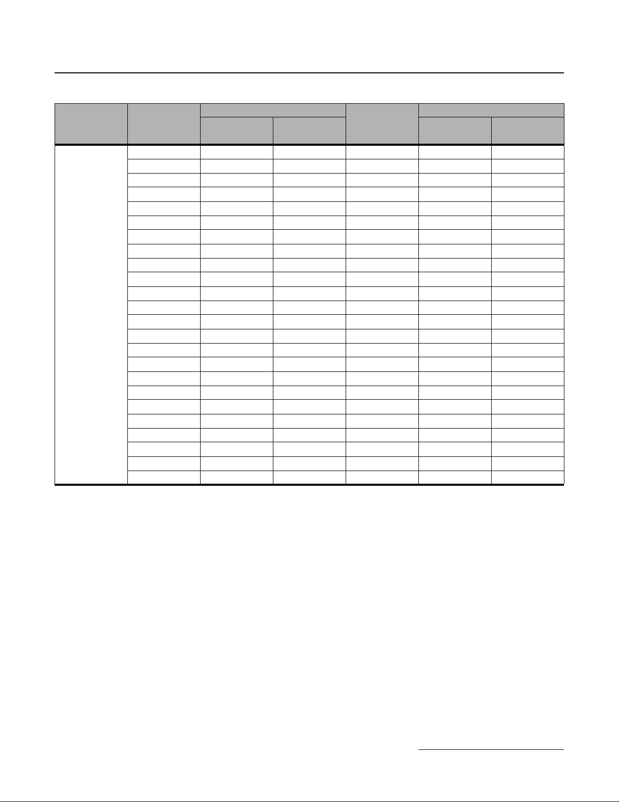
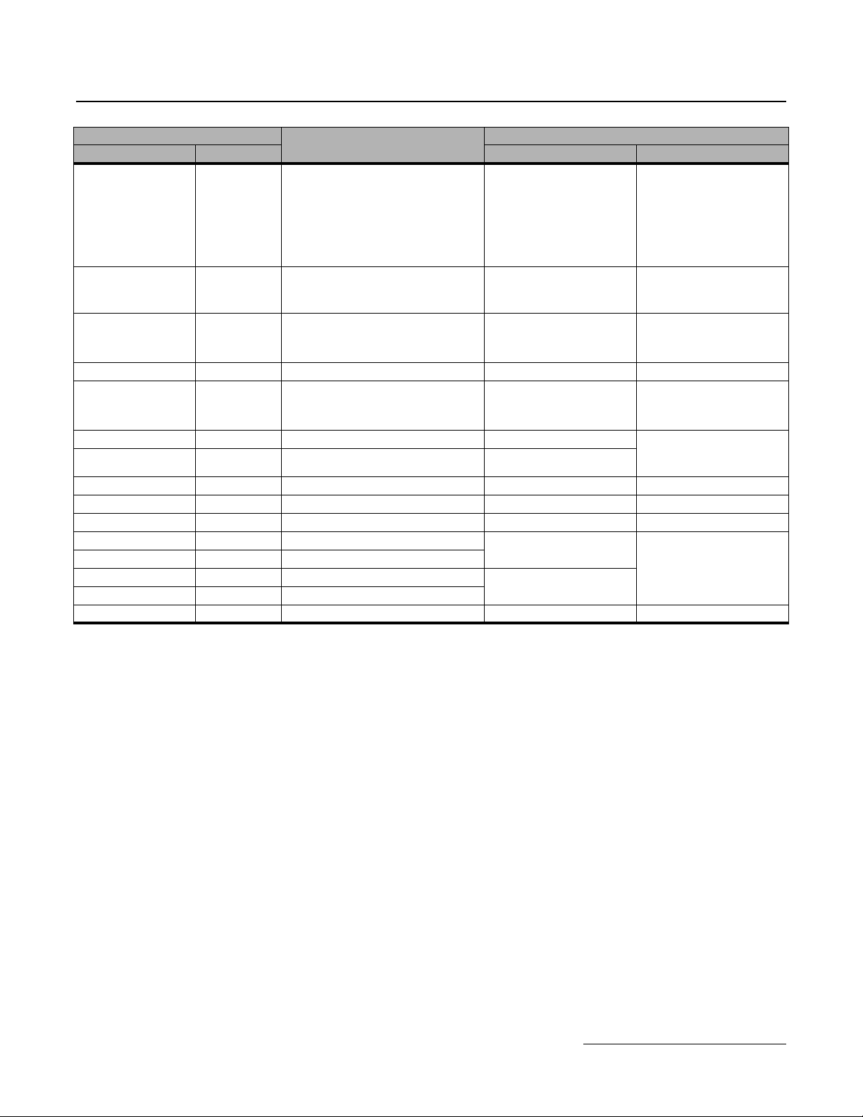
1.3 Ratings Summary
The following table summarizes the output current ratings for the G+ Series 4 and G+ Series 3 with respect to the
specific drive model.
Rated
Input Voltage
230V,
3-
G+ Series 3
Drive Model
Number
(-AFG+/FVG+)
N/A N/A N/A 2003 3.2 0.5
N/A N/A N/A 2005 5.0 0.75
2007 7.0 1.0 2007 6.9 1.0
N/A N/A N/A 2008 8.0 2.0
2009 9.6 2.0 2011 11 2.0
N/A N/A N/A 2014 14.0 3.0
2015 15.2 3.0 2017 17.5 3.0
2023 23 5.0 2025 25 5.0
2031 31 7.5 2033 33 7.5
2045 45 10 2047 47 10
2058 58 15 2060 60 15
2071 71 20 2075 75 20
2085 85 30 2085 85 30
N/A N/A N/A 2115 115 40
2145 145 50 2145 145 50
N/A N/A N/A 2180 180 60
2215 215 75 2215 215 75
2283 283 100 2283 283 100
2346 346 125 2346 346 125
N/A N/A N/A 2415 415 150
Rated Output
Current (Amps)
Heavy Duty G+ Series 4
Nominal HP
Drive Model
Number
(-G+/VG+S4)
Heavy Duty
Rated Output
Current (Amps)
Nominal HP
IMPULSE®•G+ & VG+ Series 3 to Series 4 Transition Guide August 2011
Page 6 of 54
Magnetek, Inc.
Product Transition Guide
IMPULSE
®
•G+ & VG+ Series 4
Rated
Input Voltage
460V,
3-
G+ Series 3
Drive Model
Number
(-AFG+/FVG+)
4001 1.8 0.5 4001 1.8 0.5
4002 2.1 1.0 4003 3.4 1.0
4003 3.7 2.0 4004 4.8 2.0
4005 5.3 3.0 4005 5.5 3.0
N/A N/A N/A 4007 7.2 5.0
4008 8.7 5.0 4009 9.2 5.0
4012 12.5 7.5 4014 14.8 7.5
4017 17 10 4018 18 10
4024 24 15 4024 24 15
4031 31 20 4031 31 20
4039 39 25 4039 39 25
4045 45 30 4045 45 30
4060 60 40 4060 60 40
4075 75 50 4075 75 50
4091 91 60 4091 91 60
4112 112 75 4112 112 75
4150 150 100 4150 150 100
4180 180 125 4180 180 125
N/A N/A N/A 4216 216 150
4260 260 150 4260 260 200
4304 304 250 4304 304 250
4370 370 300 4370 370 300
4477 477 350 4450 450 350
4590 590 500 4605 605 500
Rated Output
Current (Amps)
Heavy Duty G+ Series 4
Nominal HP
Drive Model
Number
(-G+/VG+S4)
Heavy Duty
Rated Output
Current (Amps)
Nominal HP
IMPULSE®•G+ & VG+ Series 3 to Series 4 Transition Guide August 2011
Page 7 of 54
Magnetek, Inc.
Product Transition Guide
IMPULSE
®
•G+ & VG+ Series 4
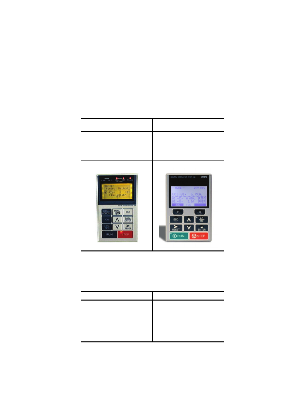
1.4 Digital Operator Comparison
Enhanced LCD operator with built-in copy function and parameter verify for the IMPULSE®•G+ & VG+
Series 4
Soft keys simplify operation and programming
LCD Contrast Adjustment
Common parameter groupings for easy transition and set-up
The IMPULSE
®
•G+ & VG+ Series 4 have a new layout for faster parameter selection
IMPULSE®•G+ & VG+ Series 3
LCD Operator
LCD Backlit Display
5 Line x 16 Characters
A Quick Start menu is added to aid in simple start up
IMPULSE®•G+ & VG+ Series 4
LCD Operator
LCD Backlit Display
5 Line x 16 Characters
New Button Layout
Soft Keys (F1/F2)
Smaller
The Quick Start menu consists of 26 parameters. The advanced menu offers full parameter access.
Menu Structure Comparison
®
IMPULSE
Modified Constants “VERIFY” Quick Settings
IMPULSE®•G+ & VG+ Series 3 to Series 4 Transition Guide August 2011
Page 8 of 54
Magnetek, Inc.
•G+ & VG+ Series 3 IMPULSE®•G + & VG+ Series 4
Operation “DRIVE” Operation
Quick Setting “QUICK” Auto-Tuning
Programming “ADV” Programming
Auto-Tuning “A.TUNE” Modified Constants
-- Monitor Menu
Product Transition Guide
IMPULSE
®
•G+ & VG+ Series 4
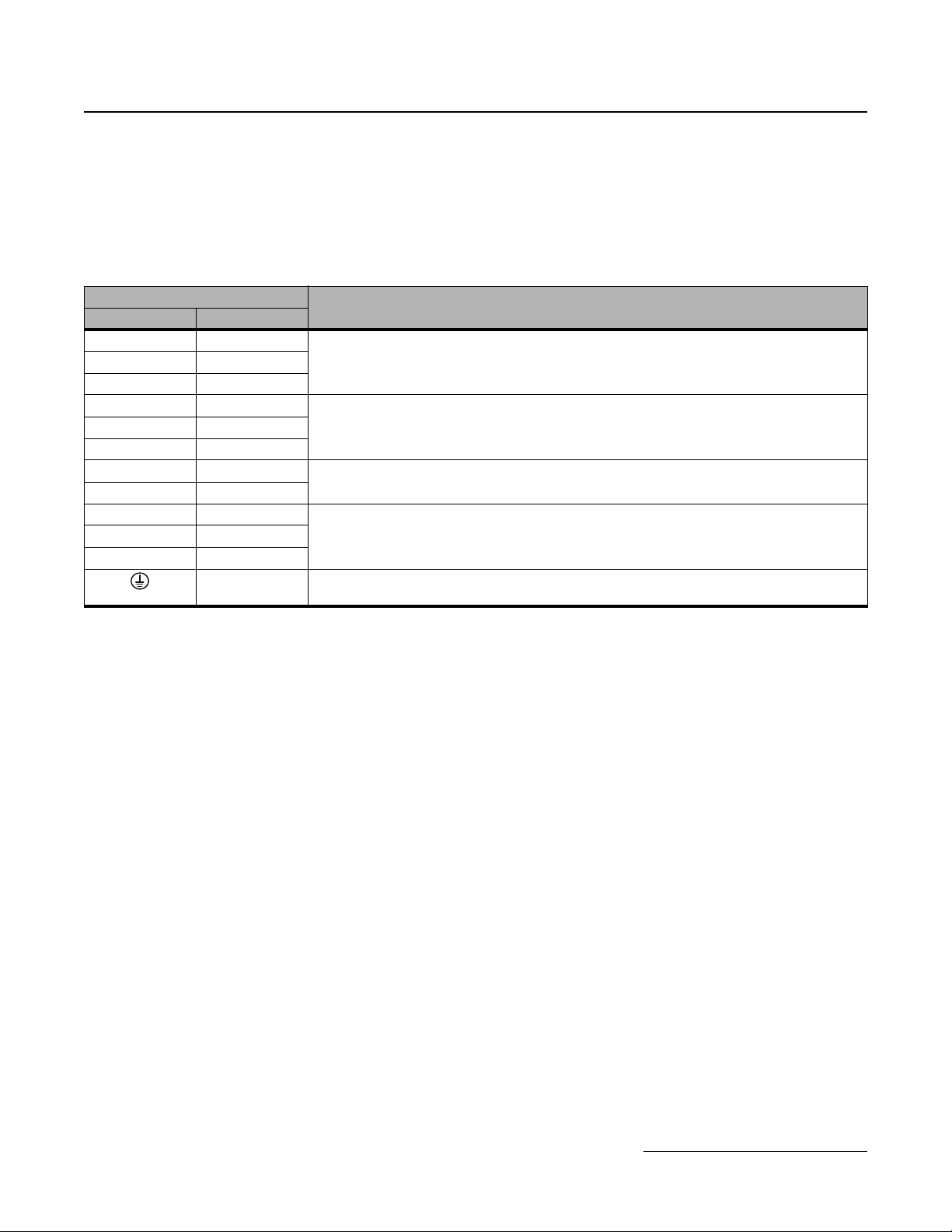
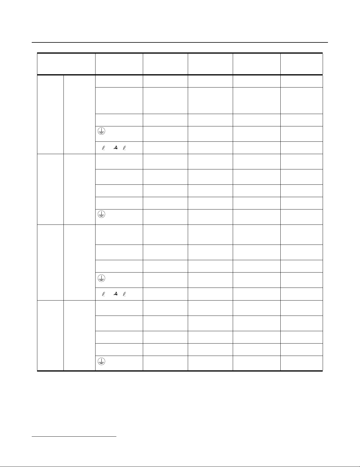
1.5 Terminals
Main Circuit Terminals
As G+ Series 3 and G+ Series 4 drive models may have different terminal sizes (depending on capacity),
the terminal must be carefully checked before replacement.
The main terminal functionality has not been changed between the G+ Series 3 and the G+ Series 4.
Main Terminals
G+ Series 3 G+ Series 4
R/L1 R/L1
T/L3 T/L3
U/T1 U/T1
W/T3 W/T3
B1 B1
B2 B2
+2 +2
+1 +1
—+3
Main circuit power supply input, connects line power to the driveS/L2 S/L2
Drive Output, connects to the motorV/T2 V/T2
Braking resistor
DC reactor connection (+1, +2) (remove shorting bar)
DC power supply input (+1, -)
Braking unit connection (+3, -)
Note
— Ground Terminal (10Ω or less)
IMPULSE®•G+ & VG+ Series 3 to Series 4 Transition Guide August 2011
Page 9 of 54
Magnetek, Inc.
Product Transition Guide
IMPULSE
Control Circuit Terminals
"—" indicates that an equivalent terminal on the other drive model does not exist.
G+ Series 4 Defaults are listed in parentheses.
Terms
MFDI: Multi-Function Digital Input
MFDO: Multi-Function Digital Output
MFAI: Multi-Function Analog Input
MFAO: Multi-Function Analog Output
Control Terminals
G+ Series 3 G+ Series 4 G+ Series 3 G+ Series 4
S1 S1 MFDI 1 (Run Forward)
S2 S2 MFDI 2 (Run Reverse)
S3 S3 MFDI 3 (Speed 2)
S4 S4 MFDI 4 (Speed 3)
S5 S5 MFDI 5 (Speed 4)
S6 S6 MFDI 6 (Speed 5)
S7 S7 MFDI 7 (External Fault)
S8 S8 MFDI 8 (Microspeed Gain 1)
X2 X2 MFDI Common -- --
M0, M1 M0, M1 MFDO (Brake Release)
M2, M3, M4 M2, M3 MFDO (X-Press Programming)
M5, M6 M5, M6 MFDO (X-Press Programming)
MA, MB, MC MA, MB, MC
+V +V Power supply for analog inputs +15 VDC, 20mA +10.5 VDC, 20mA
-V -V Power supply for analog inputs -15 VDC, 20mA -10.5 VDC, 20mA
A1 A1
A2 A2 MFAI 2 (Not Used)
A3 A3
AC AC Analog Common -- --
E (G) E (G)
®
•G+ & VG+ Series 4
Function
Fault annunciate
Terminals MA-MC: N/O
Terminals MB-MC: N/C
MFAI 1 (Master Frequency
Reference)
MFAI 3 (Master Frequency
Reference)
Ground for shielded lines and
option cards
Signal Level
Photo-coupler isolation
24 VDC, 8mA
120 VAC (with GIF7)
Form A Relay:
250 VAC, 1A
30 VDC, 1A
Form A Relay
Contact Capacity:
250 VAC, 1A
30 VDC, 1A
Form A Relay
Contact Capacity:
250 VAC, 1A
30 VDC, 1A
Form C Relay:
250 VAC, 1A
30 VDC, 1A
-10 to +10V (20kΩ)
0 to +10V (20kΩ)
-10 to +10V (20kΩ)
0 to +10V (20kΩ)
4 to 20mA (250Ω)
-10 to +10V (20kΩ)
0 to +10V (20kΩ)
-- --
Photo-coupler isolation
120 VAC
Form A Relay:
250 VAC, 1A
30 VDC, 1A
Form A Relay:
250 VAC, 1A
30 VDC, 1A
Form A Relay:
250 VAC, 1A
30 VDC, 1A
Form C Relay:
250 VAC, 1A
30 VDC, 1A
-10 to +10V (20kΩ)
0 to +10V (20kΩ)
-10 to +10V (20kΩ)
0 to +10V (20kΩ)
4 to 20mA (250Ω)
-10 to +10V (20kΩ)
0 to +10V (20kΩ)
(S4IF)
IMPULSE®•G+ & VG+ Series 3 to Series 4 Transition Guide August 2011
Page 10 of 54
Magnetek, Inc.
Product Transition Guide
IMPULSE
®
•G+ & VG+ Series 4
Control Terminals
G+ Series 3 G+ Series 4 G+ Series 3 G+ Series 4
RP RP Multi-Function Pulse Train Input
MP MP
FM FM MFAO 1 (Output frequency)
AC AC Analog Common -- --
AM AM MFAO 2 (Output current)
— H1 Safe Disable input 1 -- 24 VDC, 8mA
— H2 Safe Disable input 2 --
— HC Safe Disable common -— DM+ Safety monitor output -- 48 VDC, 8mA
— DM- Safety monitor output common -- --
R+ R+ Receive (+)
R- R- Receive (-)
S+ S+ Transmit (+)
S- S- Transmit (-)
IG IG Shield connection -- --
Pulse train output (Output
frequency)
Function
0 to 32kHz (3k) +5%
High level voltages
3.5 to 13.2
Low level voltages
0.0 to 0.8
Duty Cycle (on/off)
30% to 70%
0 to 32kHz
±5% output
(load: 1.5k)
0 to ±10VDC Max.
±5% 2mA or less
4 to 20 mA
0 to ±10VDC Max.
±5% 2mA or less
4 to 20 mA
Differential input, PHC
isolation
Differential output, PHC
isolation
Signal Level
Input Freq.: 0 to 32 kHz
Duty Cycle: 30 to 70%
High level: 3.5 to 13.2
VDC
Low Level: 0 to 0.8 VDC
Input Impedance: 3kΩ
32 kHz (max)
-10 to +10V, 2mA
0 to +10V, 2mA
4 to 20 mA
-10 to +10V, 2mA
0 to +10V, 2mA
Internal Impedance:
3.3kΩ
RS-485/422 Line Driver
115.2 kbps (max)
IMPULSE®•G+ & VG+ Series 3 to Series 4 Transition Guide August 2011
Page 11 of 54
Magnetek, Inc.

Product Transition Guide
IMPULSE
®
•G+ & VG+ Series 4
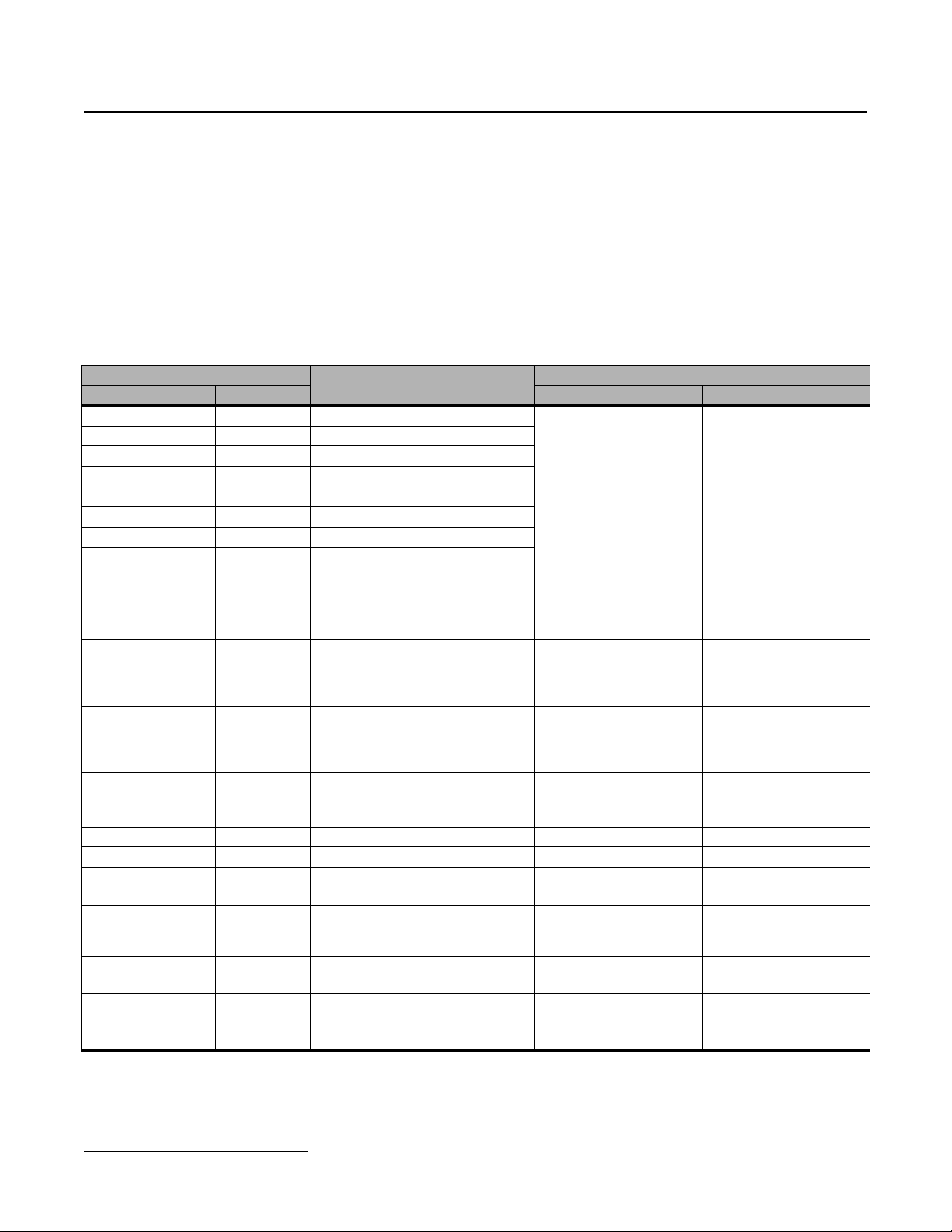
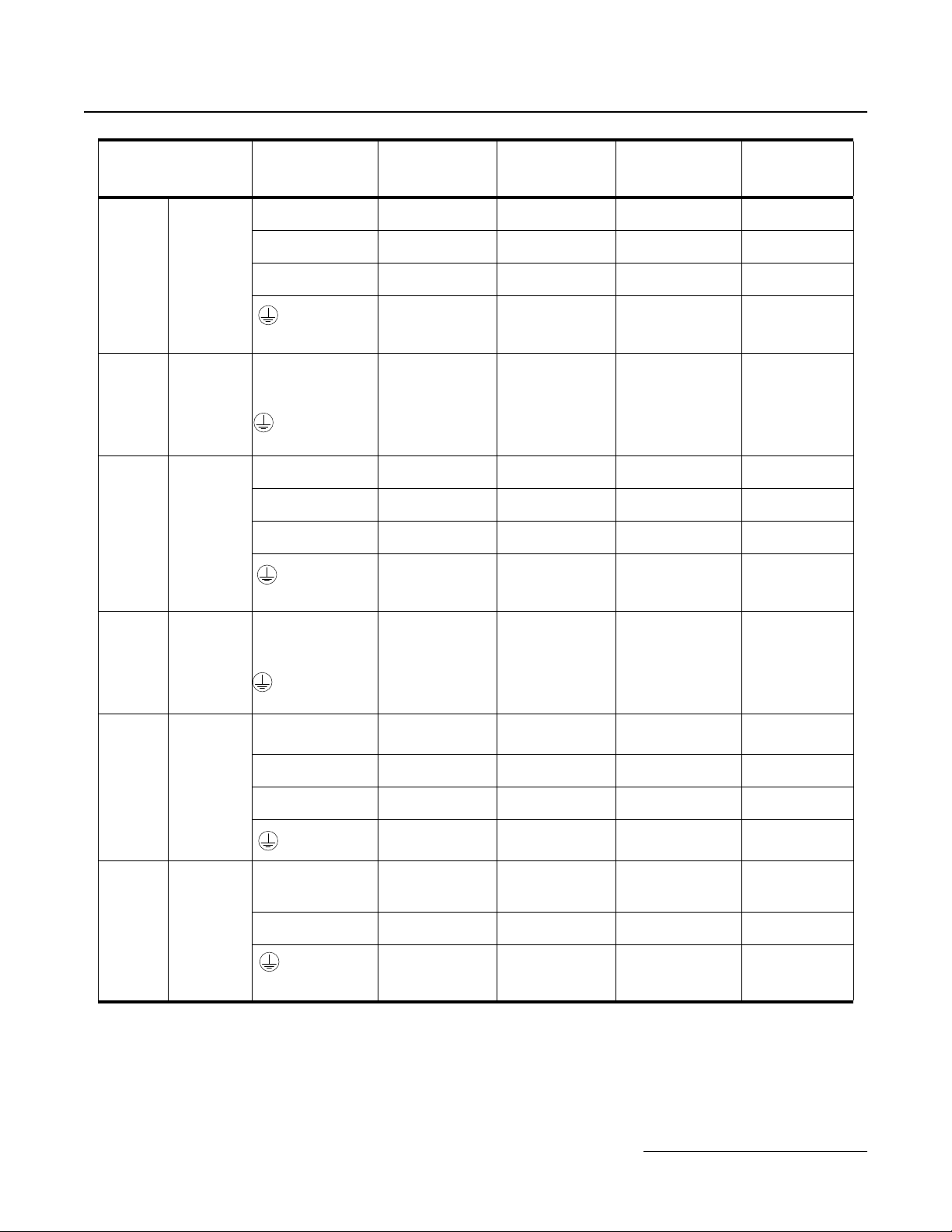
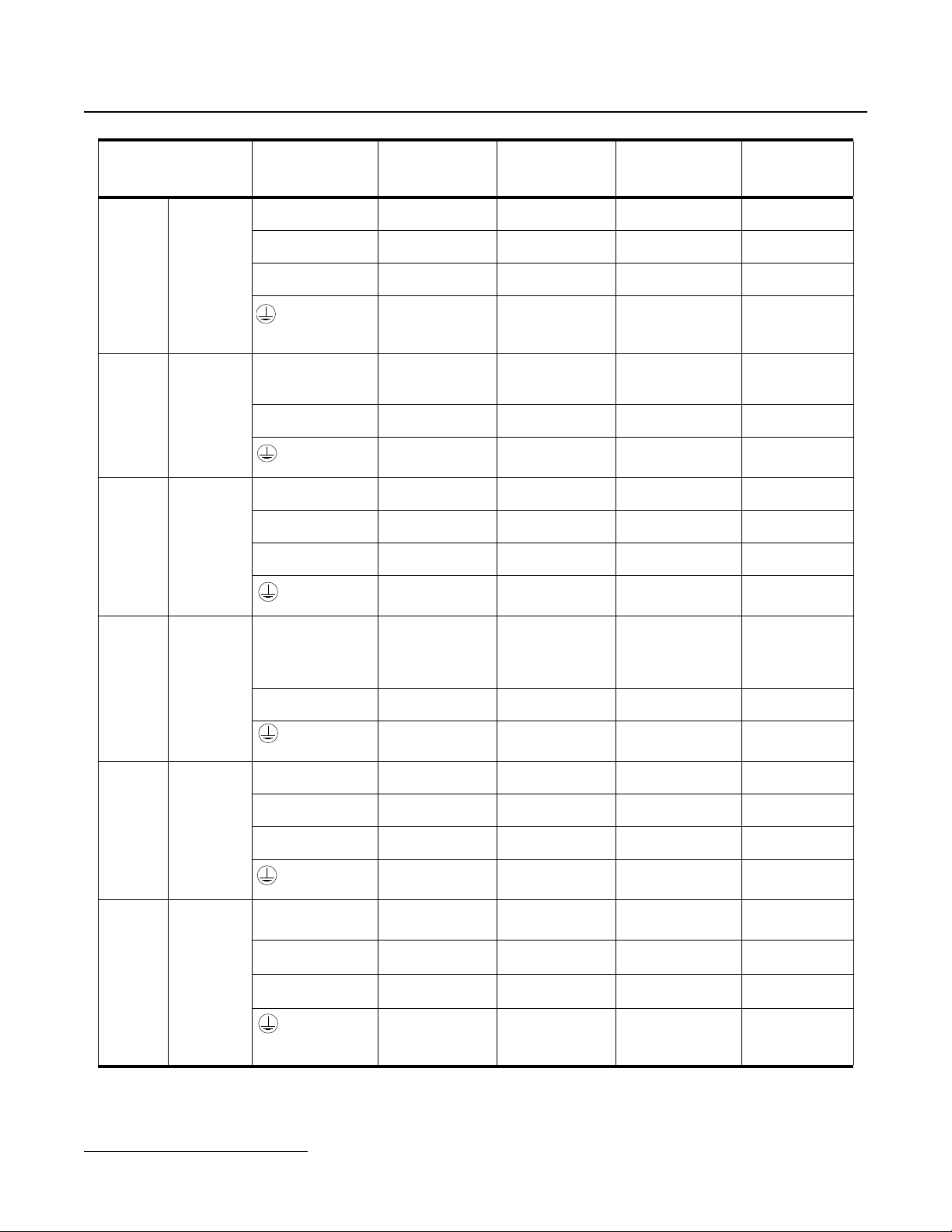
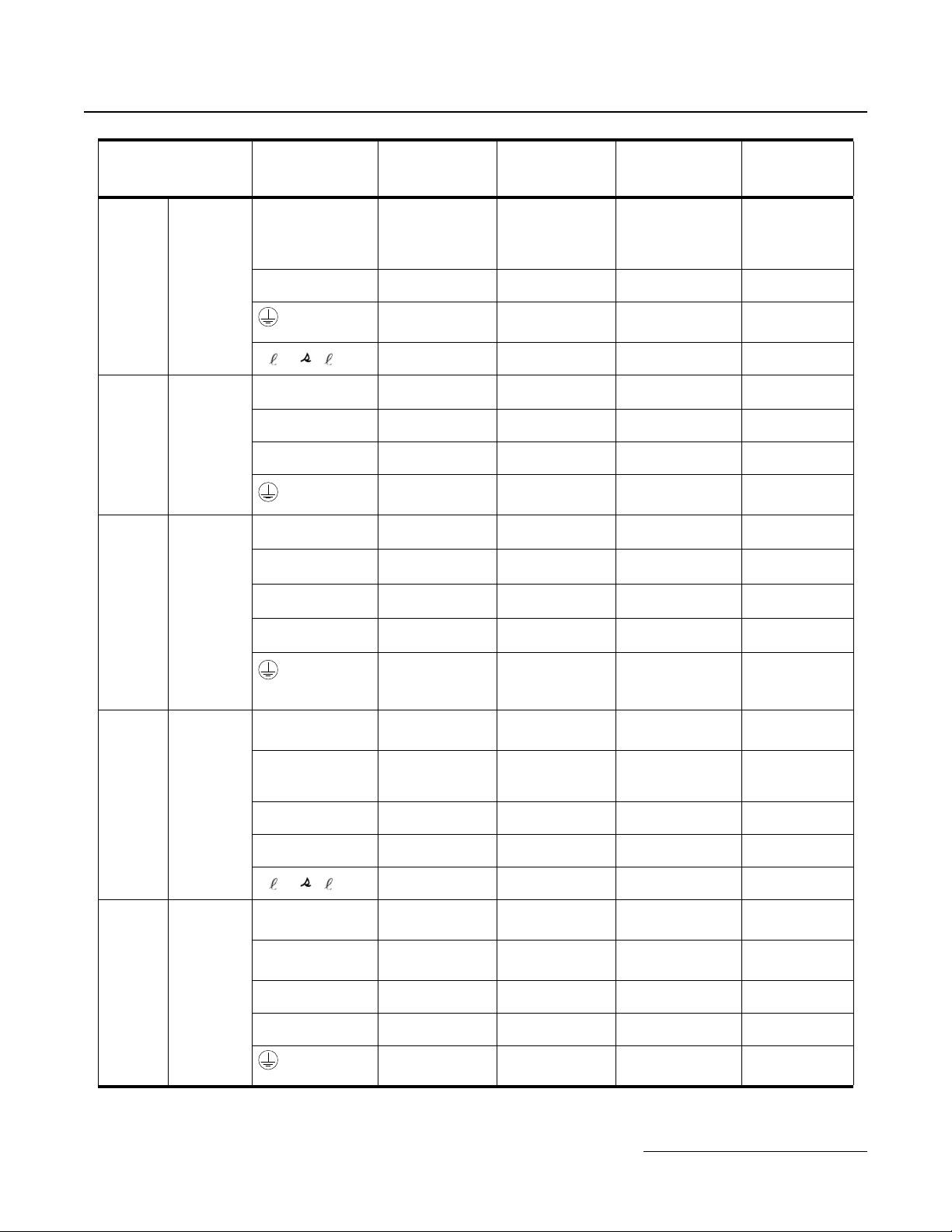
1.6 Terminal Size and Wire Gauge Comparison
3-Phase 200V Class Main Circuit Terminal Size and Gauge
IMPULSE®•G+ & VG+
Series 4
Series 3 2007
Series 4
Series 3 2009
Series 4 2011
2003
2005
2007
2008
Terminal Signal
R/L1, S/L2, T/L3,
U/T1, V/T2, W/T3,
-, +1, +2, B1, B2,
R/L1, S/L2, T/L3,
U/T1, V/T2, W/T3,
-, +1, +2, B1, B2
R/L1, S/L2, T/L3,
U/T1, V/T2, W/T3,
-, +1, +2, B1, B2,
R/L1, S/L2, T/L3,
U/T1, V/T2, W/T3,
-, +1, +2, B1, B2,
R/L1, S/L2, T/L3,
U/T1, V/T2, W/T3,
-, +1, +2, B1, B2
Ter min al Screw
M4
M4
M4
M4
M4
M4
Tightening
Tor qu e
N. m
(lb.in.)
1.2 to 1.5
(10.6 to 13.3)
1.2 to 1.5
(10.6 to 13.3)
1.2 to 1.5
(10.6 to 13.3)
1.2 to 1.5
(10.6 to 13.3)
1.2 to 1.5
(10.6 to 13.3)
1.2 to 1.5
(10.6 to 13.3)
Recommended
Possible Gauges
(AWG/kcmil)
14 to 10
14 to 10 12
14 to 10
14 to 10 12
14 to 10 14 to 10
14 to 10 12
Gauge (AWG/
kcmil)
14 to 10, 14
(Ground)
14 to 10, 12
(Ground)
R/L1,S/L2,T/L3,
U/T1,V/T2,W/T3,
Series 3 2015
Series 4
Series 3
IMPULSE®•G+ & VG+ Series 3 to Series 4 Transition Guide August 2011
Page 12 of 54
Magnetek, Inc.
2014
2017
2023
-,+1, +2, B1, B2,
R/L1,S/L2,T/L3,
-,+1, +2
U/T1,V/T2,W/T3,
B1, B2 M4
R/L1, S/L2, T/L3,
U/T1, V/T2, W/T3,
-, +1, +2, B1, B2,
M4
M4
M4
M4
1.2 to 1.5
(10.6 to 13.3)
1.2 to 1.5
(10.6 to 13.3)
1.2 to 1.5
(10.6 to 13.3)
1.2 to 1.5
(10.6 to 13.3)
1.2 to 1.5
(10.6 to 13.3)
12 to 10 12, 10 (Ground)
12 to 10
12 to 10
14 to 10 ─
10 12, 10 (Ground)
2014:14 to 10
2017: 12 to 10
2014:14 to 10
2017: 12 to 10
10 (Ground)
Product Transition Guide
IMPULSE
®
•G+ & VG+ Series 4
IMPULSE®•G+ & VG+
Series 4 2025
Series 3 2031
Series 4 2033
Terminal Signal
R/L1, S/L2, T/L3,
-, +1, +2
U/T1, V/T2, W/T3 M4
B1, B2 M4
R/L1, S/L2, T/L3,
U/T1, V/T2, W/T3,
-, +1, +2, B1, B2,
R/L1, S/L2, T/L3,
-, +1, +2
U/T1, V/T2, W/T3 M4
B1, B2 M4
Ter min al Screw
M4
M5
M5
M4
M5
Tightening
Tor qu e
N. m
(lb.in.)
1.2 to 1.5
(10.6 to 13.3)
1.2 to 1.5
(10.6 to 13.3)
1.2 to 1.5
(10.6 to 13.3)
2 to 2.5
(17.7 to 22.1)
2.5
(21.99)
1.2 to 1.5
(10.6 to 13.3)
1.2 to 1.5
(10.6 to 13.3)
1.2 to 1.5
(10.6 to 13.3)
2 to 2.5
(17.7 to 22.1)
Recommended
Possible Gauges
(AWG/kcmil)
10 to 6 8
10 to 6 8
14 to 10 ─
10 to 8 8
8 to 6 8, 10 (Ground)
8 to 6 8 to 6
8 to 6 8 to 6
12 to 10 ─
10 to 8 8
Gauge (AWG/
kcmil)
Series 3 2045
Series 4 2047
Series 3 2058
R/L1, S/L2, T/L3,
U/T1, V/T2, W/T3,
-, +1, +2, B1, B2,
R/L1, S/L2, T/L3, -,
+1, +2
U/T1, V/T2, W/T3 M6
B1, B2 M5
R/L1, S/L2, T/L3,
U/T1, V/T2, W/T3,
-, +1, +2
B1, B2 M5
M5
M6
M6
M6
M6
2.5
(21.99)
4 to 6
(35.4 to 53.1)
4 to 6
(35.4 to 53.1)
2 to 2.5
(17.7 to 22.1)
4 to 6
(35.4 to 53.1)
4 to 5
(35.2 to 43.99)
2.5
(21.99)
4 to 5
(35.2 to 43.99)
6 to 4 6, 10 (Ground)
6 to 4 6 to 4
6 to 4 6 to 4
10 to 6 ─
8 to 6 6
4 to 2 4
8 to 6 ─
48
IMPULSE®•G+ & VG+ Series 3 to Series 4 Transition Guide August 2011
Page 13 of 54
Magnetek, Inc.
Product Transition Guide
IMPULSE
®
•G+ & VG+ Series 4
IMPULSE®•G+ & VG+
Series 4 2060
Series 3
Series 4 2075
Series 3 2085
Series 4 2085
Series 4 2115
2071
Terminal Signal
R/L1, S/L2, T/L3,
-, +1, +2
U/T1, V/T2, W/T3 M8
B1, B2 M5
R/L1, S/L2, T/L3,
U/T1, V/T2, W/T3,
-, +1, +2
B1, B2 M5
R/L1, S/L2, T/L3,
-, +1, +2
U/T1, V/T2, W/T3 M8
B1, B2 M5
R/L1, S/L2, T/L3,
U/T1, V/T2, W/T3,
-, +1, R1/L11,
S1/L21, T1/L31
+3 M6
R/L1, S/L2, T/L3,
U/T1, V/T2, W/T3
-, +1 M8
B1, B2 M8
R/L1, S/L2, T/L3,
U/T1, V/T2, W/T3
-, +1 M10
B1, B2 M10
Ter min al Screw
M8
M6
M8
M6
M8
M6
M8
M8
M8
M8
M10
Tightening
Tor qu e
N. m
(lb.in.)
9 to 11
(79.7 to 97.4)
9 to 11
(79.7 to 97.4)
2 to 2.5
(17.7 to 22.1)
4 to 6
(35.4 to 53.1)
9 to 10
(79.2 to 87.97)
2.5
(21.99)
4 to 5
(35.2 to 43.99)
9 to 11
(79.7 to 97.4)
9 to 11
(79.7 to 97.4)
2 to 2.5
(17.7 to 22.1)
4 to 6
(35.4 to 53.1)
9 to 10
(79.2 to 87.97)
4 to 5
(35.2 to 43.99)
9 to 10
(79.2 to 87.97)
9 to 11
(79.7 to 97.4)
9 to 11
(79.7 to 97.4)
9 to 11
(79.7 to 97.4)
9 to 11
(79.7 to 97.4)
18 to 23
(159 to 204)
18 to 23
(159 to 204)
18 to 23
(159 to 204)
Recommended
Possible Gauges
(AWG/kcmil)
4 to 3 4 to 2
4 to 3 4 to 2
8 to 6 ─
6 to 4 6
3 to 2 2
8 to 6 ─
48
3 to 2 4 to 2
3 to 2 4 to 2
6 ─
6 to 4 6
─ 2
──
─ 6
3 to 1/0 2 to 1/0
2 to 1/0 ─
6 to 1/0 ─
6 to 4 6
1 to 2/0 2 to 1/0
1/0 to 3/0 ─
4 to 2/0 ─
Gauge (AWG/
kcmil)
M8
IMPULSE®•G+ & VG+ Series 3 to Series 4 Transition Guide August 2011
Page 14 of 54
Magnetek, Inc.
9 to 11
(79.7 to 97.4)
44
Product Transition Guide
IMPULSE
®
•G+ & VG+ Series 4
IMPULSE®•G+ & VG+
Series 3 2145
Series 4 2145
Series 4 2180
Terminal Signal
R/L1, S/L2, T/L3,
U/T1, V/T2, W/T3, -,
+1, R1/L11, S1/L21,
T1/L31
+3 M8
r/ 1, / 2
R/L1, S/L2, T/L3,
U/T1, V/T2, W/T3
-, +1 M10
+3 M10
R/L1, S/L2, T/L3 M10
U/T1, V/T2, W/T3 M10
-, +1 M10
+3 M10
Ter min al Screw
M10
M10
M4
M10
M10
Tightening
Tor qu e
N. m
(lb.in.)
17.6 to 22.5
(154.8 to 197.9)
8.8 to 10.8
(77.4 to 95.0)
17.6 to 22.5
(154.8 to 197.9)
1.3 to 1.4
(11.4 to 12.3)
18 to 23
(159 to 204)
18 to 23
(159 to 204)
18 to 23
(159 to 204)
18 to 23
(159 to 204)
18 to 23
(159 to 204)
18 to 23
(159 to 204)
18 to 23
(159 to 204)
18 to 23
(159 to 204)
Recommended
Possible Gauges
(AWG/kcmil)
─ 4/0
──
─ 2
─ 16
2/0 to 4/0, 3/0 to 4/0
(T1-3)
1 to 4/0 ─
1/0 to 4/0 ─
4 to 2 4
1/0 to 2/0 1/0 to 2/0
1/0 to 2/0 1/0 to 2/0
1 to 4/0 ─
1/0 to 4/0 ─
Gauge (AWG/
kcmil)
1/0 to 2/0
Series 3 2215
Series 4 2215
M10
R/L1, S/L2, T/L3,
-, +1
U/T1, V/T2, W/T3,
R1/L11, S1/L21,
T1/L31
+3 M8
r/ 1, / 2
R/L1, S/L2, T/L3 M12
U/T1, V/T2, W/T3 M12
-, +1 M12
+3 M10
M10
M10
M10
M4
M12
18 to 23
(159 to 204)
17.6 to 22.5
(154.8 to 197.9)
17.6 to 22.5
(154.8 to 197.9)
8.8 to 10.8
(77.4 to 95.0)
17.6 to 22.5
(154.8 to 197.9)
1.3 to 1.4
(11.4 to 12.3)
32 to 40
(283 to 354)
32 to 40
(283 to 354)
32 to 40
(283 to 354)
18 to 23
(159 to 204)
32 to 40
(283 to 354)
4 to 1/0 4
─
─
──
─ 4
─ 16
3/0 to 300
3/0 to 300
3/0 to 300 ─
2 to 300 ─
3 to 300 4
250
2-2/0
250
2-2/0
250
2-2/0
250
2-2/0
IMPULSE®•G+ & VG+ Series 3 to Series 4 Transition Guide August 2011
Page 15 of 54
Magnetek, Inc.
Product Transition Guide
IMPULSE
®
•G+ & VG+ Series 4
IMPULSE®•G+ & VG+
Series 3 2283
Series 4
Series 3 2346
Series 4 2346
2283
Terminal Signal
-, +1 M12
R/L1, S/L2, T/L3,
U/T1, V/T2, W/T3,
R1/L11, S1/L21,
T1/L31
+3 M8
r/ 1, / 2 M4
R/L1, S/L2, T/L3 M12
U/T1, V/T2, W/T3 M12
-, +1 M12
+3 M10
R/L1, S/L2, T/L3,
-, +1, R1/L11,
S1/L21, T1/L31
U/T1, V/T2, W/T3 M12
+3 M8
r/ 1, / 2
R/L1, S/L2, T/L3 M12
U/T1, V/T2, W/T3 M12
-, +1 M12
+3 M10
Ter min al Screw
M10
M12
M12
M12
M12
M4
M12
Tightening
Tor qu e
N. m
(lb.in.)
31.4 to 39.2
(276.2 to 344.8)
17.6 to 22.5
(154.8 to 197.9)
8.8 to 10.8
(77.4 to 95.0)
31.4 to 39.2
(276.2 to 344.8)
1.3 to 1.4
(11.4 to 12.3)
32 to 40
(283 to 354)
32 to 40
(283 to 354)
32 to 40
(283 to 354)
18 to 23
(159 to 204)
32 to 40
(283 to 354)
31.4 to 39.2
(276.2 to 344.8)
31.4 to 39.2
(276.2 to 344.8)
8.8 to 10.8
(77.4 to 95.0)
31.4 to 39.2
(276.2 to 344.8)
1.3 to 1.4
(11.4 to 12.3)
32 to 40
(283 to 354)
32 to 40
(283 to 354)
32 to 40
(283 to 354)
18 to 23
(159 to 204)
32 to 40
(283 to 354)
Recommended
Possible Gauges
(AWG/kcmil)
─ 3/0×2P
─
──
─ 2
─ 16
3/0 to 300
3/0 to 300
3/0 to 300 ─
3/0 to 300 ─
2 to 300 2
─
─
──
─ 2
─ 16
4/0 to 600
4/0 to 600
250 to 600 ─
3/0 to 600 ─
1 to 350 1
Gauge (AWG/
kcmil)
350
2-3/0
350
2-3/0
350
2-3/0
400
2-250
400
2-250
400
2-250
400
2-250
IMPULSE®•G+ & VG+ Series 3 to Series 4 Transition Guide August 2011
Page 16 of 54
Magnetek, Inc.

Product Transition Guide
IMPULSE
®
•G+ & VG+ Series 4
Tightening
IMPULSE®•G+ & VG+
Series 4 2415
Terminal Signal
R/L1, S/L2, T/L3 M12
U/T1, V/T2, W/T3 M12
-, +1 M12
+3 M10
Ter min al Screw
M12
Tor qu e
N. m
(lb.in.)
32 to 40
(283 to 354)
32 to 40
(283 to 354)
32 to 40
(283 to 354)
18 to 23
(159 to 204)
32 to 40
(283 to 354)
3-Phase 400V Class Main Circuit Terminal Size and Gauge
Tightening
IMPULSE®•G+ & VG+
Series 3
4001
4002
Terminal Signal
R/L1, S/L2, T/L3,
U/T1, V/T2, W/T3,
-, +1, +2, B1, B2,
Ter min al Screw
M4
Tor qu e
N. m
(lb.in.)
1.2 to 1.5
(10.6 to 13.2)
Recommended
Possible Gauges
(AWG/kcmil)
250 to 600
300 to 600
300 to 600 ─
3/0 to 600 ─
1 to 350 1
Possible Gauges
(AWG/kcmil)
14 to 10 12
Gauge (AWG/
kcmil)
400
2-250
400
2-250
Recommended
Gauge (AWG/
kcmil)
Series 4
Series 3
Series 4
Series 3 4012
4001
4003
4003
4005
4004
4005
4007
R/L1, S/L2, T/L3,
U/T1, V/T2, W/T3,
-, +1, +2, B1, B2,
R/L1, S/L2, T/L3,
U/T1, V/T2, W/T3,
-, +1, +2, B1, B2,
R/L1, S/L2, T/L3,
U/T1, V/T2, W/T3,
-, +1, +2, B1, B2
R/L1,S/L2,T/L3,
U/T1,V/T2,W/T3,
-,+1, +2, B1, B2,
M4
M4
M4
M4
M4
M4
1.2 to 1.5
(10.6 to 13.2)
1.2 to 1.5
(10.6 to 13.2)
1.2 to 1.5
(10.6 to 13.2)
1.2 to 1.5
(10.6 to 13.2)
1.2 to 1.5
(10.6 to 13.2)
1.2 to 1.5
(10.6 to 13.2)
14 to 10
14 to 10 12
14 to10 14 to 10
14 to 10 10
12 to 10 12
14 to 10 12
14 to 10, 12
(Ground)
IMPULSE®•G+ & VG+ Series 3 to Series 4 Transition Guide August 2011
Page 17 of 54
Magnetek, Inc.
 Loading...