

Magnetek Impulse-t 2006-T, Impulse-t 2010-T, Impulse-t 2012-T, Impulse-t 4004-T, Impulse-t 4005-T Instruction Manual
...
Adjustable Frequency Crane Controls
Instruction Manual
Software #5073 October 2015
Part Number: 144-26158 R3
© Copyright 2015 Magnetek


PREFACE AND SAFETY
WARNING
Improper programming of a drive can lead to unexpected, undesirable, or unsafe operation or
performance of the drive.
©2015 Magnetek
All rights reserved. This notice applies to all copyrighted materials included with this product, including, but not
limited to, this manual and software embodied within the product. This manual is intended for the sole use of the
persons to whom it was provided, and any unauthorized distribution of the manual or dispersal of its contents is
strictly forbidden. This manual may not be reproduced in whole or in part by any means whatsoever without the
expressed written permission of Magnetek.
PRODUCT SAFETY INFORMATION
Magnetek, Inc. (Magnetek) offers a broad range of radio remote control products, control products and
adjustable frequency drives, and industrial braking systems for material handling applications. This manual has
been prepared by Magnetek to provide information and recommendations for the installation, use, operation,
and service of Magnetek’s material handling products and systems (Magnetek Products). Anyone who uses,
operates, maintains, services, installs or owns Magnetek Products should know, understand, and follow the
instructions and safety recommendations in this manual for Magnetek Products.
The recommendations in this manual do not take precedence over any of the following requirements relating to
cranes, hoists lifting devices or other material handling equipment which use or include Magnetek Products:
• Instructions, manuals, and safety warnings of the manufacturers of the equipment where the Magnetek
Products are used,
• Plant safety rules and procedures of the employers and the owners of the facilities where the Magnetek
Products are being used,
• Regulations issued by the Occupational Health and Safety Administration (OSHA),
• Applicable local, state or federal codes, ordinances, standards and requirements, or
• Safety standards and practices for the industries in which Magnetek Products are used.
This manual does not include or address the specific instructions and safety warnings of these manufacturers or
any of the other requirements listed above. It is the responsibility of the owners, users and operators of the
Magnetek Products to know, understand and follow all of these requirements. It is the responsibility of the
employer to make its employees aware of all of the above listed requirements and to make certain that all
operators are properly trained. No one should use Magnetek Products prior to becoming familiar with and
being trained in these requirements and the instructions and safety recommendations for this manual.
PRODUCT WARRANTY INFORMATION
Magnetek, hereafter referred to as Company, assumes no responsibility for improper programming of a drive by
untrained personnel. A drive should only be programmed by a trained technician who has read and understands
the contents of this manual. Improper programming of a drive can lead to unexpected, undesirable, or unsafe
operation or performance of the drive. This may result in damage to equipment or personal injury. Company
shall not be liable for economic loss, property damage, or other consequential damages or physical injury
sustained by the purchaser or by any third party as a result of such programming. Company neither assumes
nor authorizes any other person to assume for Company any other liability in connection with the sale or use of
this product.
For information on Magnetek’s product warranties by product type, please visit www.magnetekmh.com.
IMPULSE•T Instruction Manual - October 2015
i

DANGER, WARNING, CAUTION, and NOTE Statements
DANGER
DANGER indicates an imminently hazardous situation which, if not avoided, will result in death
or serious injury. This signal word is to be limited to the most extreme situations.
WA R N I NG
WARNING indicates a potentially hazardous situation which, if not avoided, could result in
death or serious injury.
CAUTION
CAUTION indicates a potentially hazardous situation which, if not avoided, could result in
minor or moderate injury. It may also be used to alert against unsafe practices.
NOTE: A NOTE statement is used to notify installation, operation, programming, or
maintenance information that is important, but not hazard-related.
DANGER, WARNING, CAUTION, and NOTE statements are used throughout this manual to
emphasize important and critical information. You must read these statements to help ensure safety
and to prevent product damage. The statements are defined below.
IMPULSE•T Instruction Manual - October 2015
ii

Contents:
PREFACE AND SAFETY . . . . . . . . . . . . . . . . . . . . . . . . . . . . . . . . . . . . . . . . . . . . . . . . . i
DANGER, WARNING, CAUTION, and NOTE Statements . . . . . . . . . . . . . . . . . . . . . . . . .ii
Chapter 1: Introduction
Introduction . . . . . . . . . . . . . . . . . . . . . . . . . . . . . . . . . . . . . . . . . . . . . . . . . . . . . . . . . . 1-4
IMPULSE•T General Specifications. . . . . . . . . . . . . . . . . . . . . . . . . . . . . . . . . . . . . . . . 1-5
Chapter 2: Installation
Assessing the System Requirements . . . . . . . . . . . . . . . . . . . . . . . . . . . . . . . . . . . . . . . 2-3
IMPULSE•T Ratings and Dimensions . . . . . . . . . . . . . . . . . . . . . . . . . . . . . . . . . . . . . . . 2-5
Installing the Drive . . . . . . . . . . . . . . . . . . . . . . . . . . . . . . . . . . . . . . . . . . . . . . . . . . . . . 2-6
Chapter 3:Wiring
IMPULSE•T Wiring Practices. . . . . . . . . . . . . . . . . . . . . . . . . . . . . . . . . . . . . . . . . . . . . 3-3
IMPULSE•T Typical Connection Diagram . . . . . . . . . . . . . . . . . . . . . . . . . . . . . . . . . . . .3-5
Suggested Circuit Protection Specifications and Wire Size. . . . . . . . . . . . . . . . . . . . . . . 3-7
Chapter 4: Getting Started
Overview . . . . . . . . . . . . . . . . . . . . . . . . . . . . . . . . . . . . . . . . . . . . . . . . . . . . . . . . . . . . 4-3
Using the Keypad. . . . . . . . . . . . . . . . . . . . . . . . . . . . . . . . . . . . . . . . . . . . . . . . . . . . . . 4-4
Keypad LED and Button Functions. . . . . . . . . . . . . . . . . . . . . . . . . . . . . . . . . . . . . . .4-5
Parameters . . . . . . . . . . . . . . . . . . . . . . . . . . . . . . . . . . . . . . . . . . . . . . . . . . . . . . . . .4-7
Parameter Modes . . . . . . . . . . . . . . . . . . . . . . . . . . . . . . . . . . . . . . . . . . . . . . . . . . . . 4-9
Initialization Set-up . . . . . . . . . . . . . . . . . . . . . . . . . . . . . . . . . . . . . . . . . . . . . . . . . . 4-10
X-Press Programming. . . . . . . . . . . . . . . . . . . . . . . . . . . . . . . . . . . . . . . . . . . . . . . . 4-11
Chapter 5: Programming Features
Application . . . . . . . . . . . . . . . . . . . . . . . . . . . . . . . . . . . . . . . . . . . . . . . . . . . . . . . . . . . 5-3
Preset Reference . . . . . . . . . . . . . . . . . . . . . . . . . . . . . . . . . . . . . . . . . . . . . . . . . . . . 5-3
Reference Limits . . . . . . . . . . . . . . . . . . . . . . . . . . . . . . . . . . . . . . . . . . . . . . . . . . . . .5-4
Sequence/Reference Source . . . . . . . . . . . . . . . . . . . . . . . . . . . . . . . . . . . . . . . . . . .5-5
Acceleration/Deceleration . . . . . . . . . . . . . . . . . . . . . . . . . . . . . . . . . . . . . . . . . . . . . .5-7
Tuning . . . . . . . . . . . . . . . . . . . . . . . . . . . . . . . . . . . . . . . . . . . . . . . . . . . . . . . . . . . . . . . 5-8
DC Injection . . . . . . . . . . . . . . . . . . . . . . . . . . . . . . . . . . . . . . . . . . . . . . . . . . . . . . . .5-8
IMPULSE•T Instruction Manual— October 2015

S-Curve Acceleration/Deceleration . . . . . . . . . . . . . . . . . . . . . . . . . . . . . . . . . . . . . . 5-9
Motor Parameters. . . . . . . . . . . . . . . . . . . . . . . . . . . . . . . . . . . . . . . . . . . . . . . . . . . . . 5-10
Voltage/Frequency Pattern . . . . . . . . . . . . . . . . . . . . . . . . . . . . . . . . . . . . . . . . . . . 5-10
Motor Set-up . . . . . . . . . . . . . . . . . . . . . . . . . . . . . . . . . . . . . . . . . . . . . . . . . . . . . . 5-12
Terminal Parameters . . . . . . . . . . . . . . . . . . . . . . . . . . . . . . . . . . . . . . . . . . . . . . . . . . 5-13
Digital Inputs . . . . . . . . . . . . . . . . . . . . . . . . . . . . . . . . . . . . . . . . . . . . . . . . . . . . . . 5-13
External Fault Response Selection . . . . . . . . . . . . . . . . . . . . . . . . . . . . . . . . . . . . . 5-14
Digital Output. . . . . . . . . . . . . . . . . . . . . . . . . . . . . . . . . . . . . . . . . . . . . . . . . . . . . . 5-15
Analog Input . . . . . . . . . . . . . . . . . . . . . . . . . . . . . . . . . . . . . . . . . . . . . . . . . . . . . . 5-15
Analog Output . . . . . . . . . . . . . . . . . . . . . . . . . . . . . . . . . . . . . . . . . . . . . . . . . . . . . 5-16
Protection Parameters . . . . . . . . . . . . . . . . . . . . . . . . . . . . . . . . . . . . . . . . . . . . . . . . . 5-17
Motor Overload Protection. . . . . . . . . . . . . . . . . . . . . . . . . . . . . . . . . . . . . . . . . . . . 5-17
Stall Prevention . . . . . . . . . . . . . . . . . . . . . . . . . . . . . . . . . . . . . . . . . . . . . . . . . . . . 5-19
Hardware Protection . . . . . . . . . . . . . . . . . . . . . . . . . . . . . . . . . . . . . . . . . . . . . . . . 5-21
Automatic Reset . . . . . . . . . . . . . . . . . . . . . . . . . . . . . . . . . . . . . . . . . . . . . . . . . . . 5-21
Operator Parameters . . . . . . . . . . . . . . . . . . . . . . . . . . . . . . . . . . . . . . . . . . . . . . . . . . 5-22
Drive Selection . . . . . . . . . . . . . . . . . . . . . . . . . . . . . . . . . . . . . . . . . . . . . . . . . . . . 5-22
Monitor Parameters . . . . . . . . . . . . . . . . . . . . . . . . . . . . . . . . . . . . . . . . . . . . . . . . . 5-23
Fault Trace . . . . . . . . . . . . . . . . . . . . . . . . . . . . . . . . . . . . . . . . . . . . . . . . . . . . . . . 5-24
Maintenance . . . . . . . . . . . . . . . . . . . . . . . . . . . . . . . . . . . . . . . . . . . . . . . . . . . . . . 5-24
Chapter 6: Troubleshooting
Troubleshooting the Drive . . . . . . . . . . . . . . . . . . . . . . . . . . . . . . . . . . . . . . . . . . . . . . . 6-3
Maintenance and Inspection . . . . . . . . . . . . . . . . . . . . . . . . . . . . . . . . . . . . . . . . . . . 6-3
Motor Faults and Corrective Actions . . . . . . . . . . . . . . . . . . . . . . . . . . . . . . . . . . . . . 6-3
Drive Faults, Alarms, and Indicators . . . . . . . . . . . . . . . . . . . . . . . . . . . . . . . . . . . . . 6-4
Appendix A: Parameter Listing
IMPULSE•T Parameter Listing . . . . . . . . . . . . . . . . . . . . . . . . . . . . . . . . . . . . . . . . . . . . A-3
IMPULSE•T Instruction Manual— October 2015

Chapter 1
Introduction

This page intentionally left blank.
IMPULSE•T Instruction Manual - October 2015
1-2

WA R NI N G
Read and understand this manual before installing, operating, or servicing this drive. All
warnings, cautions, and instructions must be followed. All activity must be performed by qualified
personnel. The drive must be installed according to this manual and local codes.
Do not touch any circuitry components while the main AC power is on. In addition, you must wait
until the red “CHARGE” LED is out before performing any service on that unit (as you look at the
face of the circuitry, the “CHARGE” LED is located inside the left side of the drive). It may take as
long as 10 minutes for the charge on the main DC bus capacitors to drop to a safe level.
Do not check signals during operation.
Do not connect the main output terminals (U/T1, V/T2, W/T3) to the incoming, three-phase AC
source.
Before executing Auto-Tuning, ensure that the motor is disconnected from the drive train, and the
electric brake is set (locked) closed to ensure the load does not move. If the electric brake cannot
be released, you must ensure that the brake is disengaged for the entire tuning process.
Do not connect or disconnect wiring while the power is on. Do not remove covers or touch circuit
boards while the power is on. Do not remove or insert the digital operator while power is on.
Before servicing, disconnect all power to the equipment. The internal capacitor remains charged
even after the power supply is turned off. The charge indicator LED will extinguish when the DC
bus voltage is below 50 VDC. To prevent electric shock, wait at least ten minutes after all
indicators are OFF and measure DC bus voltage level to confirm safe level.
Do not perform a withstand voltage test on any part of the unit. This equipment uses sensitive
devices and may be damaged by high voltage.
The drive is suitable for circuits capable of delivering not more than 30,000 RMS symmetrical
Amperes, 240 VAC maximum (230 V Class) and 480 VAC maximum (460 V Class). Install
adequate branch circuit short circuit protection per applicable codes. Failure to do so may result
in equipment damage and/or personal injury.
Do not connect unapproved LC or RC interference suppression filters, capacitors, or overvoltage
protection devices to the output of the Drive. These devices may generate peak currents that
exceed drive specifications.
IMPULSE•T Instruction Manual - October 2015
1-3

Introduction
The IMPULSE•T drive is the next generation of Magnetek, Inc. drives, providing compact and
economical crane control. The drive maintains a similar footprint size to previous generation drives.
The drive includes:
• Volts/Hertz Control
• Up to 8 Discrete Speed References
• 1 multi-function digital output
• 120 VAC interface card (standard)
• Multi-function analog input (0–10 VDC, 4-20 mA, 0–20 mA)
• 40:1 speed range
• DC injection braking, ramp to stop
• Electronic reversing of motor leads
This manual will provide support for the basic and advanced operating features of IMPULSE•T. For
additional information, visit www.magnetekmh.com/manuals.htm.
IMPULSE•T Instruction Manual - October 2015
1-4

IMPULSE•T General Specifications
230V Class - Standard
Specification Specification Values and Information for Each 230V-Class Model
2006-T 2010-T 2012-T
Rated output current (A) 6.0 9.6 12.0
Capacity (kVA) 2.3 3.7 4.6
460V Class - Standard
Specification Specification Values and Information for Each 460V-Class Model
4002-T 4004-T 4005-T 4009-T
Rated output current (A) 2.1 4.1 5.4 8.8
Capacity (kVA) 1.6 3.1 4.1 6.7
230V and 460V Classes
Specification Specification Value and Information for All Models
Certification cULus, CE, RoHS
Rated input power supply volts & freq 3-phase 200–240 V or 380–480 V; 50/60 Hz
Allowable input voltage fluctuation -15% or +10% of nominal
Allowable input frequency fluctuation ±5% of nominal
Control method Fully digital; sine-wave, pulse-width modulated
Maximum output voltage (VAC) Max output voltage 3-phase, 200–240 V; 380–480 V (proportional to input voltage).
Rated frequency (Hz) Up to twice motor nameplate RPM, 60 Hz standard (150 Hz, consult factory)
Output speed control range 40:1 - V/f
Output frequency accuracy ±0.01%—with digital reference command
±0.5%—with analog reference command; 10 bits/10 V
Frequency reference resolution Digital: 0.01 Hz
Output frequency resolution 0.01 Hz
Overload capacity 120% of rated output current of the drive for 1 minute
Remote frequency reference sources 0–10 VDC (2k); 4–20 mA (250), 0–20 mA
Accel/decel times 0.0 to 25.5 seconds
Braking torque 125% or more with dynamic braking
Motor overload protection UL recognized electronic thermal overload relay; field-programmable
Overcurrent protection level 200% of drive rated current
Circuit protection Ground fault
Overvoltage protection level Approximately 410 VDC (230 V Class), 820 VDC (460 V Class)
Undervoltage protection level Approximately 190 VDC (230 V Class), 380 VDC (460 V Class)
Heatsink overtemperature Thermostat trips at 184–212°F (90–100°C), dependent on drive capacity
Stall prevention Separate functions for accel
Other protection features Lost output phase, failed-oscillator, mechanical overload, and internal braking
transistor failure.
DC bus voltage indication Charge LED is on until DC bus voltage drops below 50 VDC
Location Indoors; requires protection from moisture, corrosive gases, and liquids
Ambient operating temperature 14° to 122°F (-10° to 50°C) for open chassis
IMPULSE•T Instruction Manual - October 2015
1-5

Specification Specification Value and Information for All Models
Storage temperature -4° to 140°F (-20° to 60°C)
Humidity 95% relative; noncondensing
Vibration 1 G less than 20 Hz; 0.2 G for 20–55 Hz
Elevation 3300 Ft. (1000 m) or less
AC Reactor Specifications
Reactors, both as input (line) and output (load) devices, protect adjustable frequency drives, motors,
and other load devices against excessive voltage and current.
The following guidelines may help determine input and output reactor requirements:
• Install an input reactor if the power source is greater than 500kVA.
• Ensure that the drive-to-motor wiring distance is less than 150 ft. unless appropriate reactors,
filters, and/or Inverter Duty motor is used.
• Install an output reactor if a device, such as a power limit switch, is used to disconnect the motor
from the drive.
• Install one output reactor per drive for a multiple-drive arrangement requiring reactor protection.
• For a multiple-drive arrangement, an input reactor for each drive is recommended for optimal
protection. However, if the drives are within two drive sizes of each other, a single input reactor
can be used. The reactor must be rated at amperage equal to or greater than the sum of the
amperage for all the drives.
Table 1-1: 230V Class
Model Number - Finned 230 V Part Number Maximum Amps of Reactor
2006-T REA230-2 8
2010-T REA230-3 12
2012-T REA230-3 12
Table 1-2: 460V Class
Model Number - Finned 460 V Part Number Maximum Amps of Reactor
4002-T REA460-1 2
4004-T REA460-3 4
4005-T REA460-3 4
4009-T REA460-5 8
IMPULSE•T Instruction Manual - October 2015
1-6
IMPULSE•T External Resistor Specifications
Table 1-3: External Resistor Specifications
Model Number -
230 Volts
460 Volts
* External resistor
IMPULSE•T
Finned
2006-T EDB2003CT EDB2004DTP*
2010-T EDB2006CT EDB2006DTP*
2012-T EDB2009CT EDB2011DTP*
4002-T EDB4001CT EDB4002DTP*
4004-T EDB4003CT EDB4004DTP*
4005-T EDB4004CT EDB4005DTP*
4009-T EDB4007CT EDB4007DTP*
Resistor Part No. Resistor Part No.
CMAA Class C CMAA Class D
Traverse
IMPULSE•T Instruction Manual - October 2015
1-7

This page intentionally left blank.
IMPULSE•T Instruction Manual - October 2015
1-8

Chapter 2
Installation

This page intentionally left blank.
IMPULSE•T Instruction Manual - October 2015
2-2

Assessing the System Requirements
WA R NI N G
• When preparing to mount the IMPULSE•T drive, lift it by its base. Never lift it by the front
cover.
• Mount the drive on nonflammable material.
• The IMPULSE•T drive generates heat. For the most effective cooling possible, mount it
vertically. For more details, refer to the “IMPULSE•T Ratings and Dimensions” in this
chapter.
• When mounting units in an enclosure, install a fan or other cooling device to keep the
enclosure temperature below 122°F (50C).
Failure to observe these warnings may result in equipment damage.
It is important to know how you are going to use the drive before you start installation and wiring. You
will need to know your requirements for the following components:
•Motion (traverse only)
• Motor HP, RPM, and FLA
• Speed control method (2-speed, 3-speed, multi-step, etc.)
• Stopping method (Decelerate/Ramp to Stop)
•Wire size
• Grounding location and method
Choosing a Location
Be sure that the drive is mounted in a location protected against the following conditions:
• Extreme cold and heat. Use only within the ambient temperature range:
Open Chassis: +14 to 122F (-10 to 50C)
• Direct sunlight (not for use outdoors)
• Rain, moisture
• High humidity
• Oil sprays, splashes
• Salt spray
• Dust or metallic particles in the air
• Corrosive gases (e.g. sulfurized gas or liquids)
• Radioactive substances
• Combustibles (e.g. thinner, solvents, etc.)
• Physical shock, vibration
• Magnetic noise (e.g. welding machines, power devices, etc.)
IMPULSE•T Instruction Manual - October 2015
2-3

IMPULSE•T System Components And External Devices
Optional Drive Components
• 120 VAC Interface Card (Part Number T-IF-120VAC)
• 24 VAC Interface Card (Part Number T-IF-24VAC)
• 48 VAC Interface Card (Part Number T-IF-48VAC)
• Quick Start Guide (Part Number 144-25086)
As-Required Drive Components
• AC reactor—line or load
• DC bus reactor
• External dynamic braking resistor(s)
Required External Devices
• Motor
• User input device (pendant, joystick, PC, PLC, radio, or infrared control)
• External circuit protection devices (fuses or circuit breakers). See “Suggested Circuit
Protection Specifications and Wire Size” on page 3-7.
• R-C surge suppressors on contactor coils
IMPULSE•T Instruction Manual - October 2015
2-4
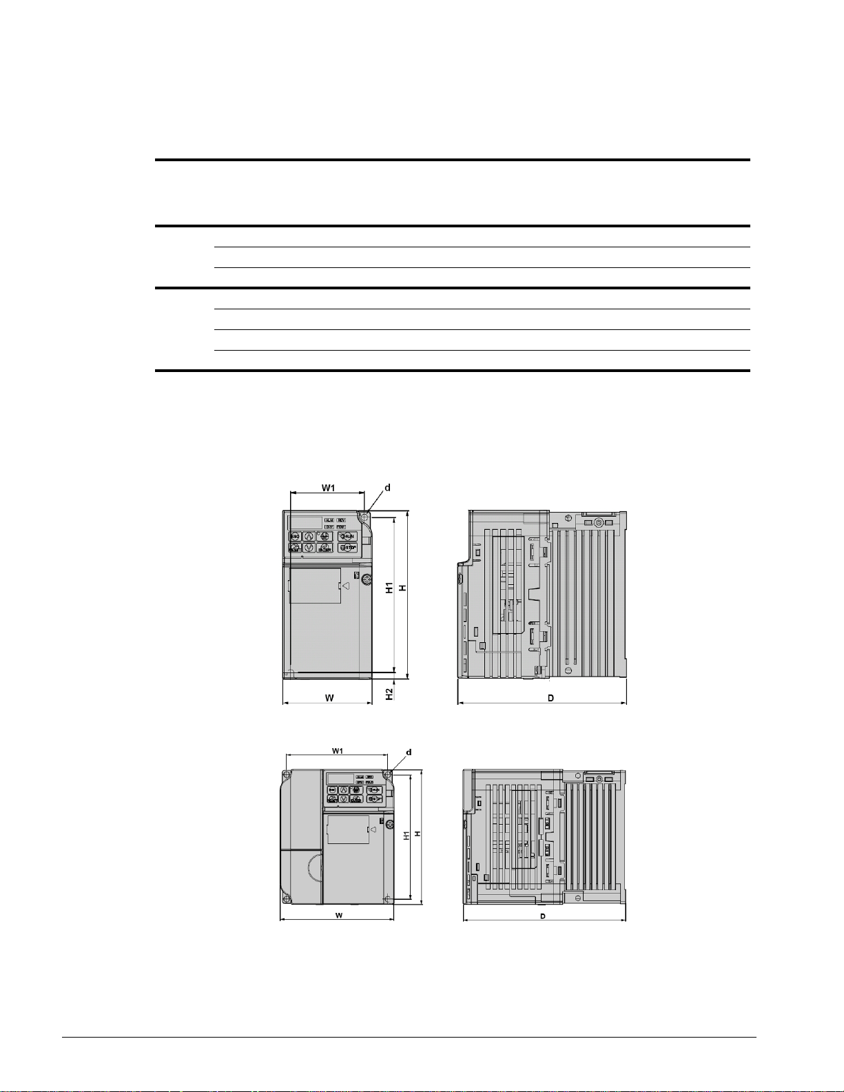
IMPULSE•T Ratings and Dimensions
Table 2-1: Ratings and Dimensions
Voltage Model W H D W1 H1 d Wt. in Lbs.
Total Heat
Loss (W)**
Dimensions in Inches
2006-T 2.7 5.0 5.0 2.2 4.6 M4 2.4 44.7
230V
460V
NOTE: Applications such as high duty cycles in conjunction with high ambient temperatures or other
** Heat loss for carrier frequency of 2.0 kHz.
2010-T 4.3 5.0 5.1 3.8 4.6 M4 3.8 77.5
2012-T 4.3 5.0 5.4 3.8 4.6 M4 3.8 91.7
4002-T 4.3 5.0 3.9 3.8 4.6 M4 2.7 32.4
4004-T 4.3 5.0 5.4 3.8 4.6 M4 3.8 47.3
4005-T 4.3 5.0 6.1 3.8 4.6 M4 3.8 66.3
4009-T 4.3 5.0 6.1 3.8 4.6 M4 3.8 95.1
unique environmental conditions can impact drive ratings. Please consult factory. Due to
ongoing improvements, data is subject to change without notice.
Figure 2-1: Dimensions
IMPULSE•T Instruction Manual - October 2015
2-5
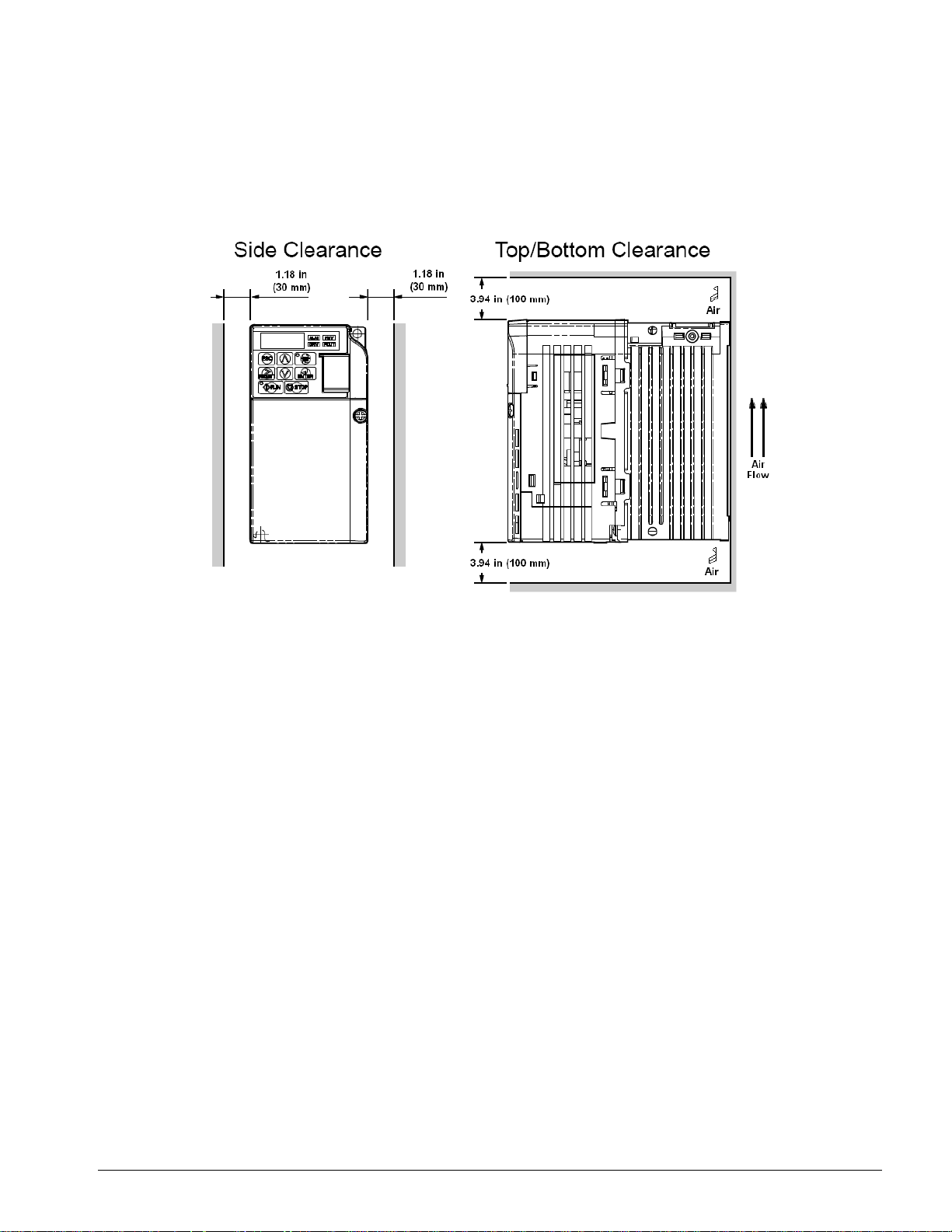
Installing the Drive
The following figure shows the minimum clearances when mounting the drive in standard or side-byside installations.
Figure 2-2: Standard Installation
IMPULSE•T Instruction Manual - October 2015
2-6

Chapter 3
Wiring

This page intentionally left blank.
IMPULSE•T Instruction Manual - October 2015
3-2

IMPULSE•T Wiring Practices
WA R N I NG
Before you wire the drive, review the following practices to help ensure that your system is wired
properly.
• Connect the incoming three-phase AC source to terminals R/L1, S/L2, and T/L3.
• Connect the motor leads to terminals U/T1, V/T2, and W/T3.
• Ensure that the drive-to-motor wiring distance is less than 150 ft (45.72 m) unless appropriate
reactors and/or filters are used.
• Install a line reactor between the output of the drive in applications that require a disconnecting
means between the drive’s output and the motor. Use a “make before break” auxiliary contact
with the disconnect means and the hardware base block of the drive.
• Use contacts between the PLC output and the drive 120/24/48 VAC input card. If using a solid
state output from a PLC (TRIAC) to a 120/24/48 VAC input card, use a 5KΩ, 5 Watt resistor
between the signal and X2.
• If the power source is 500 kVA or greater, or more than 10 times the inverter kVA rating, ensure
that there is at least 3 percent impedance between the power source and the drive input. To
accomplish this, you can install a DC reactor between inverter terminals +1 and +2, or use an
AC line reactor on the input of the drive. If you don’t provide enough impedance, excessive peak
currents could damage the input power supply circuit.
• Comply with “Suggested Circuit Protection Specifications and Wire Size” on page 3-7.
• Use time delay fuses, which are sized at 150% of drive's continuous-rated current, for drive input
protection.
• Use appropriate R-C or MOV type surge absorbers across the coil of all contactors and relays in
the system. Failure to do so could result in noise-related, nuisance fault incidents.
• Use external dynamic braking resistors for all applications.
• Do not ground the drive with any large-current machines.
• Before you use any welding or high-current machines near the crane, disconnect all line and
ground wiring.
• Do not let the wiring leads come in contact with the drive enclosure.
• Do not connect power factor correction capacitors to the drive input or output.
• Hard-wire the drive and motor (e.g., festoon cable). Do not use sliding collector bars.
• If you have a user input device or interface board that is remote, use shielded cable between the
drive input terminals and the interface output terminals or user input device(s).
• Before turning on the drive, check the output circuit (U/T1, V/T2, and W/T3) for possible short
circuits and ground faults.
• Increase the wire size by one size for every 250 ft (76.2 m) between the drive and motor;
suggested for center driven cranes, trolleys, and bridges (voltage drop is significant at low
frequencies).
• When using more than one transformer for the drive's power, properly phase each transformer.
IMPULSE•T Instruction Manual - October 2015
3-3

• To reverse the direction of rotation, interchange any two motor leads (U/T1, V/T2, or W/T3).
Changing R/L1, S/L2, or T/L3 will not affect the shaft rotation direction or change parameter B3-
04.
• Use shielded cable for all low-level DC speed reference signals (0 to 10 VDC, 4 to 20 mA).
Ground the shield only at the drive side.
• Please observe National Electrical Code (NEC) guidelines when wiring electrical devices.
NOTE: Failure to observe these warnings may result in equipment damage.
IMPULSE•T Instruction Manual - October 2015
3-4
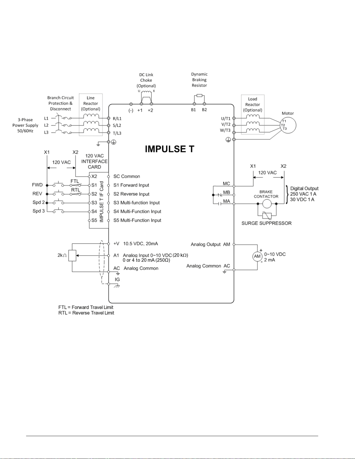
IMPULSE•T Typical Connection Diagram
Figure 3-1: IMPULSE•T Typical Connection Diagram
IMPULSE•T Instruction Manual - October 2015
3-5
 Loading...