

Magnetek IMPULSE G Plus Series 4, IMPULSE VG Plus Series 4 Installation Manual
PROFINET Installation Manual
August 2014
Part Number: 144-27019
© Copyright 2014 Magnetek

Table of Contents
1. Preface and Safety. . . . . . . . . . . . . . . . . . . . . . . . . . . . . . . . . . . . . . . . . . . . . .4
Applicable Documentation. . . . . . . . . . . . . . . . . . . . . . . . . . . . . . . . . . . . . . . . . . . . . . . . . . . . 4
Terms. . . . . . . . . . . . . . . . . . . . . . . . . . . . . . . . . . . . . . . . . . . . . . . . . . . . . . . . . . . . . . . . . . . . 5
Registered Trademarks. . . . . . . . . . . . . . . . . . . . . . . . . . . . . . . . . . . . . . . . . . . . . . . . . . . . . . 5
Supplemental Safety Instructions . . . . . . . . . . . . . . . . . . . . . . . . . . . . . . . . . . . . . . . . . . . . . . 5
General Safety. . . . . . . . . . . . . . . . . . . . . . . . . . . . . . . . . . . . . . . . . . . . . . . . . . . . . . . . . . . . . 6
2. Product Overview . . . . . . . . . . . . . . . . . . . . . . . . . . . . . . . . . . . . . . . . . . . . . .7
About This Product . . . . . . . . . . . . . . . . . . . . . . . . . . . . . . . . . . . . . . . . . . . . . . . . . . . . . . . . . 7
3. Receiving . . . . . . . . . . . . . . . . . . . . . . . . . . . . . . . . . . . . . . . . . . . . . . . . . . . . .8
Option Package Contents . . . . . . . . . . . . . . . . . . . . . . . . . . . . . . . . . . . . . . . . . . . . . . . . . . . . 8
Tools Required for Installation . . . . . . . . . . . . . . . . . . . . . . . . . . . . . . . . . . . . . . . . . . . . . . . . . 8
4. Option Components . . . . . . . . . . . . . . . . . . . . . . . . . . . . . . . . . . . . . . . . . . . .9
SI-EP3 PROFINET Option . . . . . . . . . . . . . . . . . . . . . . . . . . . . . . . . . . . . . . . . . . . . . . . . . . . 9
Terminal CN1. . . . . . . . . . . . . . . . . . . . . . . . . . . . . . . . . . . . . . . . . . . . . . . . . . . . . . . . . . . . . . 9
Option LED Display . . . . . . . . . . . . . . . . . . . . . . . . . . . . . . . . . . . . . . . . . . . . . . . . . . . . . . . . 10
Power-Up Diagnostics. . . . . . . . . . . . . . . . . . . . . . . . . . . . . . . . . . . . . . . . . . . . . . . . . . . . . . .11
5. Installation Procedure. . . . . . . . . . . . . . . . . . . . . . . . . . . . . . . . . . . . . . . . . .12
Section Safety . . . . . . . . . . . . . . . . . . . . . . . . . . . . . . . . . . . . . . . . . . . . . . . . . . . . . . . . . . . . 12
Prior to Installing the Option . . . . . . . . . . . . . . . . . . . . . . . . . . . . . . . . . . . . . . . . . . . . . . . . . 14
Installing the Option. . . . . . . . . . . . . . . . . . . . . . . . . . . . . . . . . . . . . . . . . . . . . . . . . . . . . . . . 15
GSD/GSDML Files . . . . . . . . . . . . . . . . . . . . . . . . . . . . . . . . . . . . . . . . . . . . . . . . . . . . . . . . 20
6. Option Related Drive Parameters. . . . . . . . . . . . . . . . . . . . . . . . . . . . . . . . .21
7. PROFINET Messaging. . . . . . . . . . . . . . . . . . . . . . . . . . . . . . . . . . . . . . . . . .25
PROFINET Overview . . . . . . . . . . . . . . . . . . . . . . . . . . . . . . . . . . . . . . . . . . . . . . . . . . . . . . 25
PROFIdrive Communication Profile. . . . . . . . . . . . . . . . . . . . . . . . . . . . . . . . . . . . . . . . . . . . 25
Magnetek-Specific Control and Status Words . . . . . . . . . . . . . . . . . . . . . . . . . . . . . . . . . . . . 28
8. Communication . . . . . . . . . . . . . . . . . . . . . . . . . . . . . . . . . . . . . . . . . . . . . . .29
Introduction to PROFINET IO . . . . . . . . . . . . . . . . . . . . . . . . . . . . . . . . . . . . . . . . . . . . . . . . 29
PROFINET IO in SI-EP3 . . . . . . . . . . . . . . . . . . . . . . . . . . . . . . . . . . . . . . . . . . . . . . . . . . . . 29
Option High Priority Alarm Codes . . . . . . . . . . . . . . . . . . . . . . . . . . . . . . . . . . . . . . . . . . . . . 41
Option Low Priority Alarm Codes. . . . . . . . . . . . . . . . . . . . . . . . . . . . . . . . . . . . . . . . . . . . . . 43
Identification and Maintenance Functions (I&M) . . . . . . . . . . . . . . . . . . . . . . . . . . . . . . . . . . 44
Diagnostic and Alarms. . . . . . . . . . . . . . . . . . . . . . . . . . . . . . . . . . . . . . . . . . . . . . . . . . . . . . 44
Alarm Mechanism . . . . . . . . . . . . . . . . . . . . . . . . . . . . . . . . . . . . . . . . . . . . . . . . . . . . . . . . . 45
9. Web Interface. . . . . . . . . . . . . . . . . . . . . . . . . . . . . . . . . . . . . . . . . . . . . . . . .46
Main Tab . . . . . . . . . . . . . . . . . . . . . . . . . . . . . . . . . . . . . . . . . . . . . . . . . . . . . . . . . . . . . . . . 46
IMPULSE®•G+/VG+ Series 4 Profinet Installation Manual - August 2014
2

Drive Status Tab. . . . . . . . . . . . . . . . . . . . . . . . . . . . . . . . . . . . . . . . . . . . . . . . . . . . . . . . . . . 47
Network Tab . . . . . . . . . . . . . . . . . . . . . . . . . . . . . . . . . . . . . . . . . . . . . . . . . . . . . . . . . . . . . . 48
Doc Links Tab. . . . . . . . . . . . . . . . . . . . . . . . . . . . . . . . . . . . . . . . . . . . . . . . . . . . . . . . . . . . . 49
Email Alerts Tab . . . . . . . . . . . . . . . . . . . . . . . . . . . . . . . . . . . . . . . . . . . . . . . . . . . . . . . . . . . 50
10. Troubleshooting . . . . . . . . . . . . . . . . . . . . . . . . . . . . . . . . . . . . . . . . . . . . . 55
Drive-Side Error Codes . . . . . . . . . . . . . . . . . . . . . . . . . . . . . . . . . . . . . . . . . . . . . . . . . . . . . 55
11. Specifications . . . . . . . . . . . . . . . . . . . . . . . . . . . . . . . . . . . . . . . . . . . . . . . 60
IMPULSE®•G+/VG+ Series 4 Profinet Installation Manual - August 2014
3
1. Preface and Safety
Magnetek manufactures products used as components in a wide variety of industrial systems and
equipment. The selection and application of Magnetek products remain the responsibility of the
equipment manufacturer or end user. Magnetek accepts no responsibility for the way its products are
incorporated into the final system design. Under no circumstances should any Magnetek product be
incorporated into any product or design as the exclusive or sole safety control. Without exception, all
controls should be designed to detect faults dynamically and fail safely under all circumstances. All
systems or equipment designed to incorporate a product manufactured by Magnetek must be
supplied to the end user with appropriate warnings and instructions as to the safe use an d operation
of that part. Any warnings provided by Magnetek must be promptly provided to the end user.
Magnetek offers an express warranty only as to the quality of it s product s in conforming to st andards
and specifications published in the Magnetek manual. NO OTHER WARRANTY, EXPRESS OR
IMPLIED, IS OFFERED. Magnetek assumes no liability for any personal injury, property damage,
losses, or claims arising from misapplication of its products.
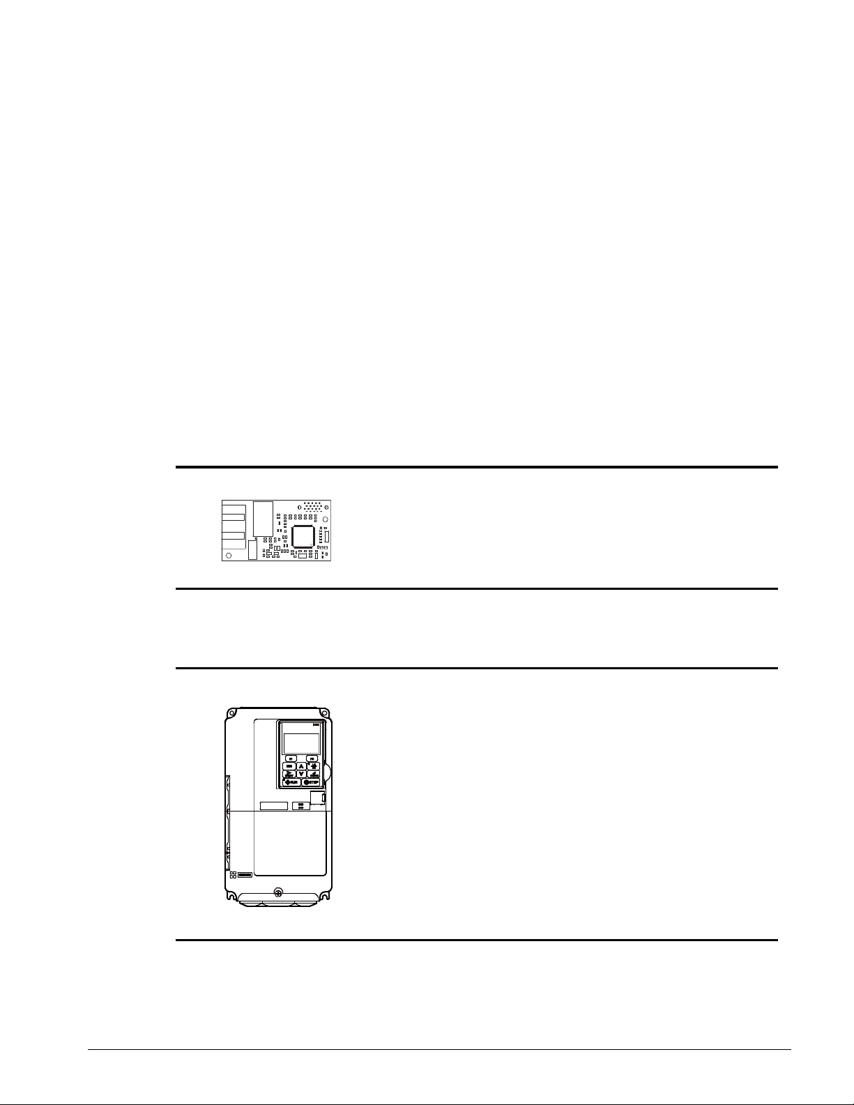
Applicable Documentation
The following manuals are available for the SI-EP3 option:
Option
IMPULSE
Option SI-EP3 PROFINET
Installation Manual
Manual No: 144-27019
®
•G+/VG+ Series 4
Read this manual first.
The installation manual is
packaged with the option and
contains detailed information
about the option, information
required to install the option and
set up related drive parameters.
MPULSE®•G+/VG+ Series 4 Drive
IMPULSE
Instruction Manual
®
•G+/VG+ Series 4
The drive manuals cover basic
installation, wiring, operation
procedures, functions, troubleshooting,
and maintenance information. The
manuals also include important
information about parameter settings
and drive tuning.
Access http://www.magnetek.com to
obtain Magnetek instruction manuals.
IMPULSE®•G+/VG+ Series 4 Profinet Installation Manual - August 2014
4

Terms
DANGER
DANGER indicates an imminently hazardous situation which, if not avoided, will result in
death or serious injury. This signal word is to be limited to the most extreme situations.
WA R NI N G
WARNING indicates a potentially hazardous situa tion which, if not avoided, could resu lt in
death or serious injury.
CAUTION
CAUTION indicates a potentially hazardous situation which, if not avoided, could result in
minor or moderate injury. It may also be used to alert against unsafe practices.
NOTICE
NOTICE indicates an equipment damage message.
Drive: IMPULSE®•G+/VG+ Series 4
Option: IMPULSE
®
•G+/VG+ Series 4 SI-EP3 PROFINET option
Registered Trademarks
• All trademarks are the property of their respective owners.
Supplemental Safety Instructions
Read and understand this manual before installing, operating, or servicing this option. The option
must be installed according to this manual and local codes.
The following conventions are used to indicate safety messages in this manual. Failure to heed
these messages could result in serious or possibly even fatal injury or damage to the products or to
related equipment and systems.
NOTE: A NOTE statement is used to notify installation, operation, programming, or maintenance
information that is important, but not hazard-related.
IMPULSE®•G+/VG+ Series 4 Profinet Installation Manual - August 2014
5
General Safety
DANGER
Heed the safety messages in this manual.
Failure to comply will result in death or serious injury.
The operating company is responsible for any injuries or equipment damage resulting
from failure to heed the warnings in this manual.
NOTICE
Do not modify the drive or option circuitry.
Failure to comply could result in damage to the drive or option and will void the warranty.
Magnetek is not responsible for any modification of the product made by the user. This
product must not be modified.
Do not expose the drive to halogen group disinfectants.
Failure to comply may cause damage to the electrical components in the option.
Do not pack the drive in wooden materials that have been fumigated or sterilized.
Do not sterilize the entire package after the product is packed.
General Precautions
• The diagrams in this section may include options and drives without covers or safety shields to
illustrate details. Be sure to reinstall covers or shields before operating any devices. The option
should be used according to the instructions described in this manual.
• Any illustrations, photographs, or examples used in this manual are provided as examples only
and may not apply to all products to which this manual is applicable.
• The products and specifications described in this manual or the content and presentation of the
manual may be changed without notice to improve the product and/or the manual.
• When ordering new copies of the manual, cont act your Magnetek representative and provide the
manual number shown on the front cover.
IMPULSE®•G+/VG+ Series 4 Profinet Installation Manual - August 2014
6

2. Product Overview
About This Product
The PROFINET SI-EP3 option connects the Series 4 drive to a PROFINET network and facilitates
the exchange of data.
This manual explains the handling, installation, and specifications of this product.
The PROFINET SI-EP3 option is a simple networking solution that reduces the cost and time to wire
and install factory automation devices, while providing interchangeability of like components from
multiple vendors.
By installing the option to a drive, it is possible to do the following from a PROFINET master device:
• operate the drive,
• monitor the operation status of the drive, and/or
• change parameter settings.
SI-EP3 is PROFINET Conformance Class A certified.
IMPULSE®•G+/VG+ Series 4 Profinet Installation Manual - August 2014
7
3. Receiving
Please perform the following tasks upon receiving the option:
• Inspect the option for damage. Contact the shipper immediately if the option appears damaged
upon receipt.
• Verify receipt of the correct model by checking the model number printed on the option
nameplate.
• Contact your supplier if you have received the wrong model or the option does not function
properly.
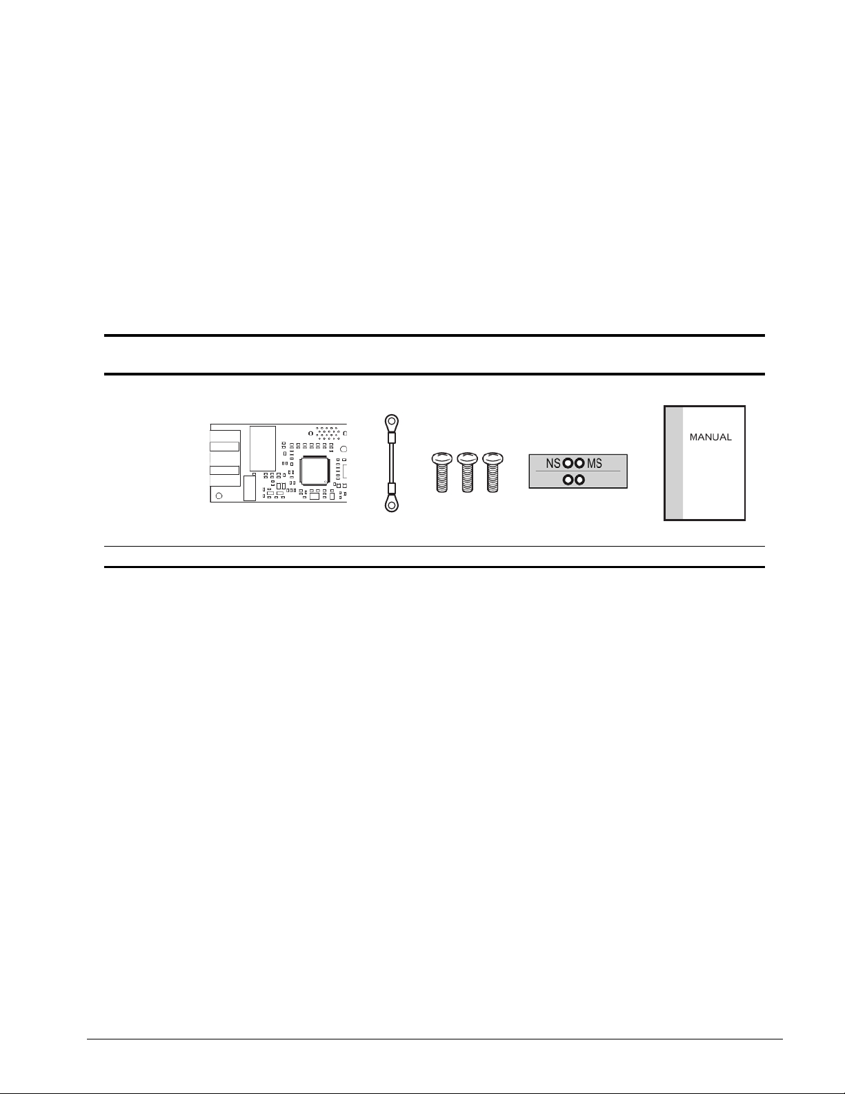
Option Package Contents
Description Option
--
Quantity 1 1 3 1 1
Ground
Wire
Screws (M3) LED Label Installation Manual
Tools Required for Installation
• A Phillips screwdriver (M3 metric/#1, #2 U.S. standard size*) is required to install the option and
remove drive front cove rs.
• Diagonal cutting pliers (required for some drive models).
• A small file or medium grit sandpaper ( required for some drive models).
*Screw sizes vary by drive capacity. Select a screwdriver appropriate for the drive capacity.
NOTE: Tools required to prepare option cables for wiring are not listed in this manual.
IMPULSE®•G+/VG+ Series 4 Profinet Installation Manual - August 2014
8
4. Option Components
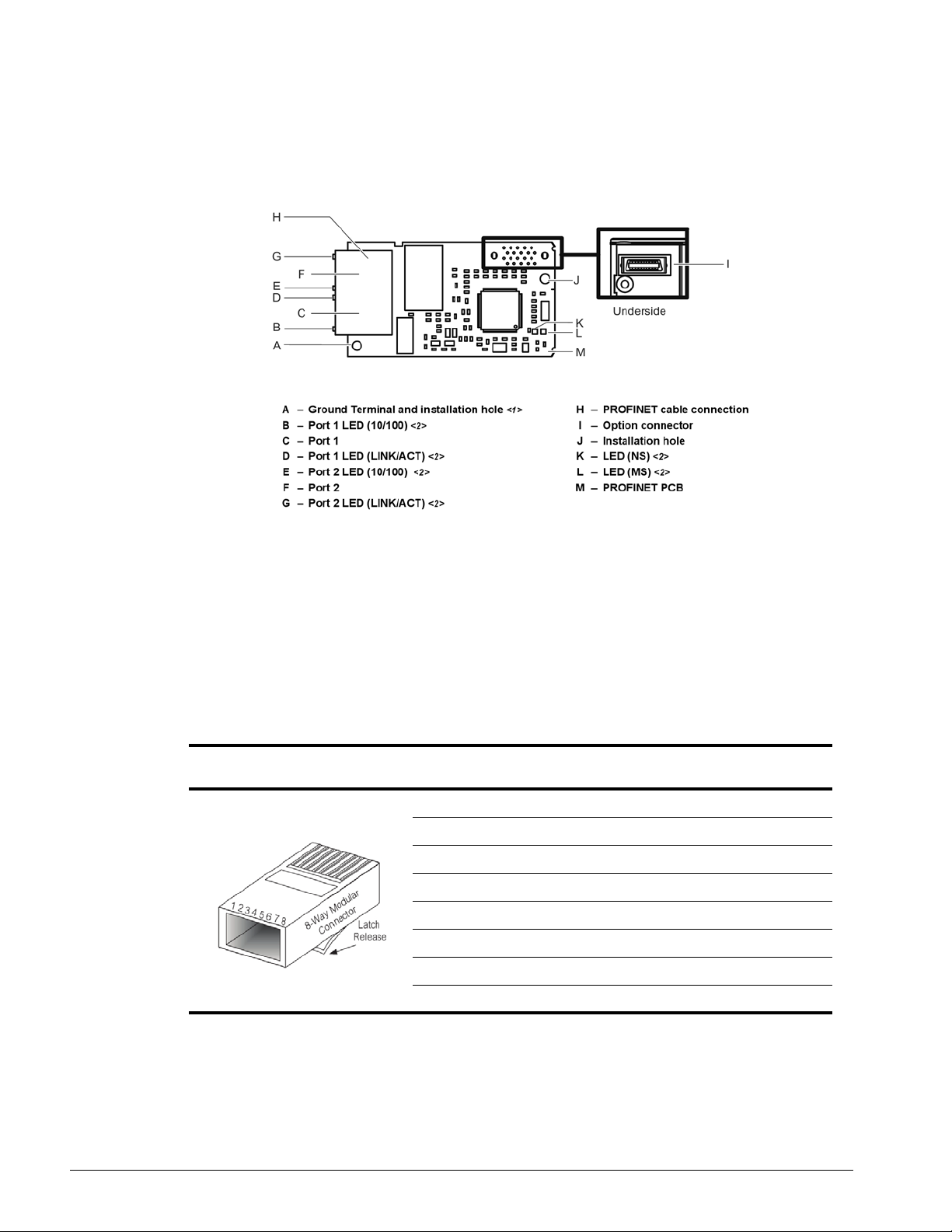
SI-EP3 PROFINET Option
<1> The ground wire provided in the option shipping package must be connected during installation.
<2> Refer to Option LED Display on page 10 for details on the LEDs.
Figure 1: Option (Top View)
Terminal CN1
The communication connector on the option is a modular RJ45 female connector designated CN1.
CN1 is the connection point for a customer-supplied male Ethernet network communication cable.
Table 1: Male 8-way Ethernet Modular Connector (Customer-Supplied)
Male EtherNet 8-Way Modular
Connector
<1> Not used for 10 Mbps and 100 Mbps networks.
Pin Description
1 (Pair 2) Transmit data (TXD) +
2 (Pair 2) Transmit data (TXD) 3 (Pair 3) Receive data (RXD) +
4 (Pair 1) Not used <1>
5 (Pair 1) Not used <1>
6 (Pair 3) Receive data (RXD) 7 (Pair 4) Not used <1>
8 (Pair 4) Not used <1>
IMPULSE®•G+/VG+ Series 4 Profinet Installation Manual - August 2014
9

Option LED Display
The option has six LEDs:
Bi-color Status LEDs:
• Module status (MS) red/green
• Network status (NS) red/green
PROFINET LEDs (2 each):
• Network speed-10/100 yellow
• Link status and network activity-Link/Act green
The operational states of the option LEDs after th e power-up diagnostic LED sequence is completed
are described in Table 2: Option LED States. Th e states with a number in parenthesis are the
number of pulses of 250 ms on, 250 ms off cycles, followed by 500 ms off, then repeating the cycle.
Wait at least two seconds for the power-up diagnostic process to complete before verifying LED
states.
Table 2: Option LED States
Name
MS (visible through
drive cover)
NS (visible through
drive cover)
10/100 (visible at
RJ45 jack)
LINK/ACT (visible at
RJ45 jack)
Indication
Operating Status Remarks
Color Status
-- OFF Power Supply OFF Power is not being supplied to the drive.
Green ON Option operating
Green Flashing (1) Diagnostics Diagnostic data available.
Green Flashing (2) Configuration tool Identified by a configuration tool.
Red ON Default MAC or fatal error occurred
Red Flashing (1) Configurational error (non-fatal) Configuration error.
Red Flashing (2) No IP (non-fatal) No IP address assigned.
Red Flashing (3) No station name (non-fatal) No station name assigned.
Red Flashing (4) Init failure (non-fatal) Failed to initialize module.
Green/
Red
-- OFF Offline or Power supply OFF -Green ON Connected
Green Flashing Connected and stopped
Red ON BUS fault Unrecoverable BUS fault.
Red Flashing (1) Lost communication Host communication is temporarily lost.
Red Flashing (2) Lost link No link detected to network.
Yellow OFF 10 Mbps is established -Yellow ON 100 Mbps is established -Green OFF Link is not established -Green ON Link is established --
Green Flashing
Flashing Option self-test The option is in self-test mode.
Link is established and there is
network activity
The option is operating normally and initialization
is complete.
Default MAC address has been programmed or
the option has detected an unrecoverable error.
Connection established with I/O controller and in
RUN mode.
Connection established with I/O controller and in
STOP mode.
--
IMPULSE®•G+/VG+ Series 4 Profinet Installation Manual - August 2014
10

Power-Up Diagnostics
An LED test is performed each time the drive is powered up. The initial boot sequence may take
several seconds. After the LEDs have completed the diagnostic LED sequence, as shown in Table 3:
Power-Up Diagnostic LED Sequence, the option is successfully initialized. The LEDs then assume
operational conditions as shown in Table 2: Option LED States.
Table 3: Power-Up Diagnostic LED Sequence
Sequence Module Status (MS) Network Status (NS) Time (ms)
1 Green OFF 250
2 Red OFF 250
3 Green OFF -4 Green Green 250
5 Green Red 250
6 Green OFF --
IMPULSE®•G+/VG+ Series 4 Profinet Installation Manual - August 2014
11
5. Installation Procedure
DANGER
Electric Shock Hazard
Do not connect or disconnect wiring while the power is on.
Failure to comply will result in death or serious injury.
Disconnect all power to the drive, wait at least five minutes after all indicators are off,
measure the DC bus voltage to confirm safe level, and check for unsafe voltages before
servicing. The internal capacitor remains charged after the power supply is turned off.
The charge indicator LED will extinguish when the DC bus voltage is below 50 VDC.
WARNING
Electrical Shock Hazard
Do not remove the option cover while the power is on.
Failure to comply could result in death or serious injury.
The diagrams in this section may include options and drives without covers or safety
shields to show details. Be sure to reinstall covers or shields before operating any
devices. Use the option according to the instructions described in this manual.
Do not allow unqualified personnel to use equipment.
Failure to comply could result in death or serious injury.
Maintenance, inspection, and replacement of parts must be performed only by
authorized personnel familiar with installation, adjustment, and maintenance of this
product.
Do not touch circuit boards while the power to the dr ive is on.
Failure to comply could result in death or serious injury.
Do not use damaged wires, stress the wiring, or damage the wire insulation.
Failure to comply could result in death or serious injury.
Fire Hazard
Tighten all terminal screws to the specified tightening torque.
Loose electrical connections could result in death or serious injury by fire due to
overheating of electrical connections.
Section Safety
IMPULSE®•G+/VG+ Series 4 Profinet Installation Manual - August 2014
12

NOTICE
Damage to Equipment
Observe proper electrostatic discharge (ESD) procedures when handling the option,
drive, and circuit boards.
Failure to comply may result in ESD damage to circuitry.
Never shut the power off while the drive is running or outputting voltage.
Failure to comply may cause the application to operate incorrectly or damage the drive.
Do not operate damaged equipment.
Failure to comply may cause further damage to the equipment.
Do not connect or operate any equipment with visible damage or missing parts.
Do not use unshielded cable for control wiring.
Failure to comply may cause electrical interference resulting in poor system
performance.
Use shielded twisted-pair wires and ground the shield to the ground terminal of the
drive.
Properly connect all pins and connectors.
Failure to comply may prevent proper operation and possibly damage equipment.
Check wiring to ensure that all connections are correct after installing the option and
connecting any other devices.
Failure to comply may result in damage to the option.
IMPULSE®•G+/VG+ Series 4 Profinet Installation Manual - August 2014
13
Prior to Installing the Option
Prior to installing the option, wire the drive, make necessary connections to the drive terminals, and
verify that the drive functions normally without the option installed. Refer to the Instruction Manual
packaged with the drive for information on wiring and connecting the drive.
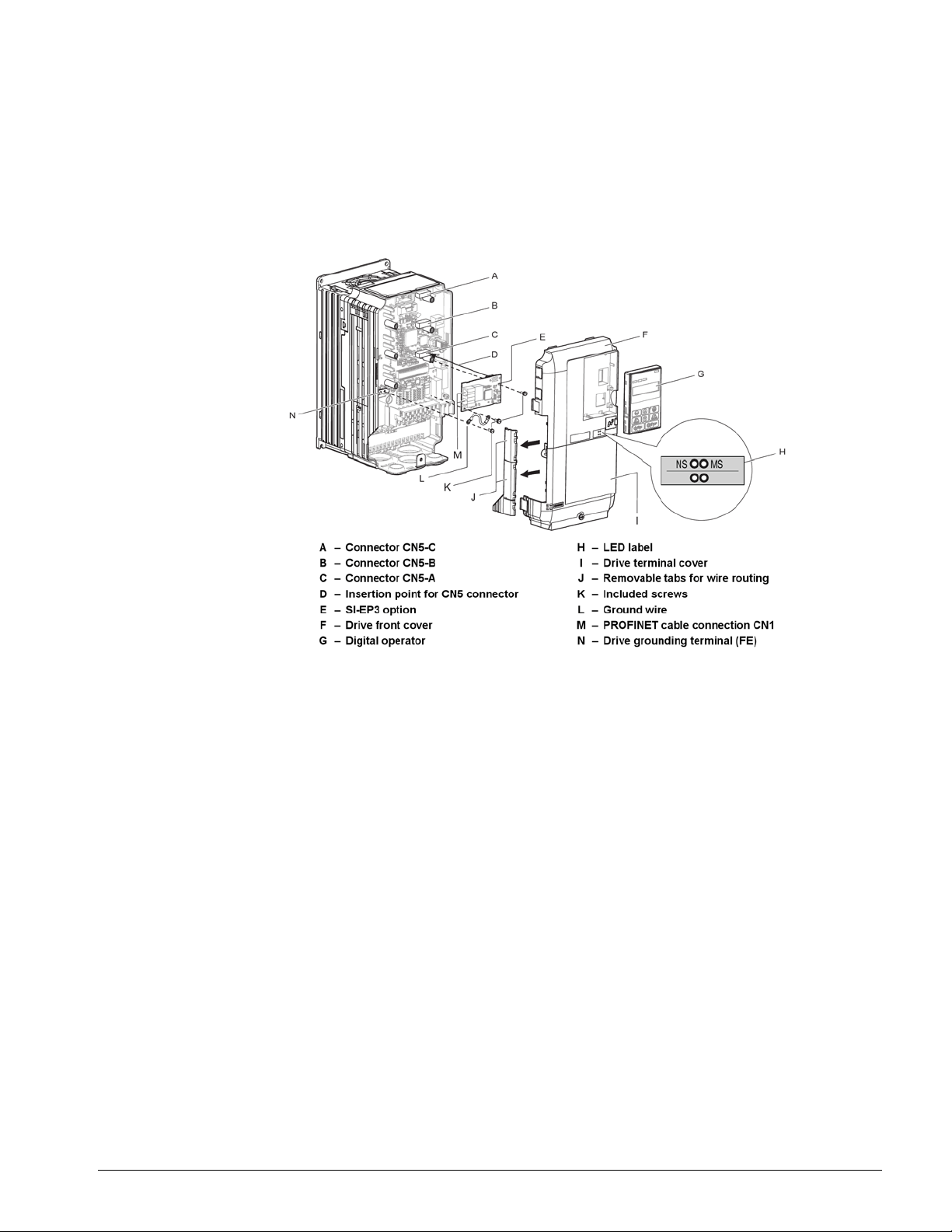
Figure 2 shows an exploded view of the drive with the option and related components for refere nce.
Figure 2: Drive Components with Options
IMPULSE®•G+/VG+ Series 4 Profinet Installation Manual - August 2014
14

Installing the Option
DANGER
Electrical Shock Hazard.
Do not connect or disconnect wiring while the power is on. Failure to comply will result in
death or serious injury . Before installing the option, disconnect all power to the drive. The
internal capacitor remains charged eve n after the power supply is turned off. The charge
indicator LED will extinguish when the DC bus voltage is below 50 VDC. To prevent
electric shock, wait at least five minutes after all indicators are off and measure the DC
bus voltage level to confirm safe level.
NOTICE
Damage to Equipment
Observe proper electrostatic discharge procedures (ESD) when handling the option,
drive, and circuit boards. Failure to comply may result in ESD damage to circuitry.
Remove the front covers of the drive before installing the option. Refer to the Instruction Manual for
directions on removing the front covers. Cover removal varies depending on drive size. This option
can be inserted only into the CN5-A connector located on the drive control board.
1. Shut off power to the drive, wait the appropriate amount of time for voltage to dissipate, then
remove the digital operator (G) and front covers (F, I). Front cover removal varies by model.
Figure 3: Remove the Front Covers and Digital Operator
IMPULSE®•G+/VG+ Series 4 Profinet Installation Manual - August 2014
15
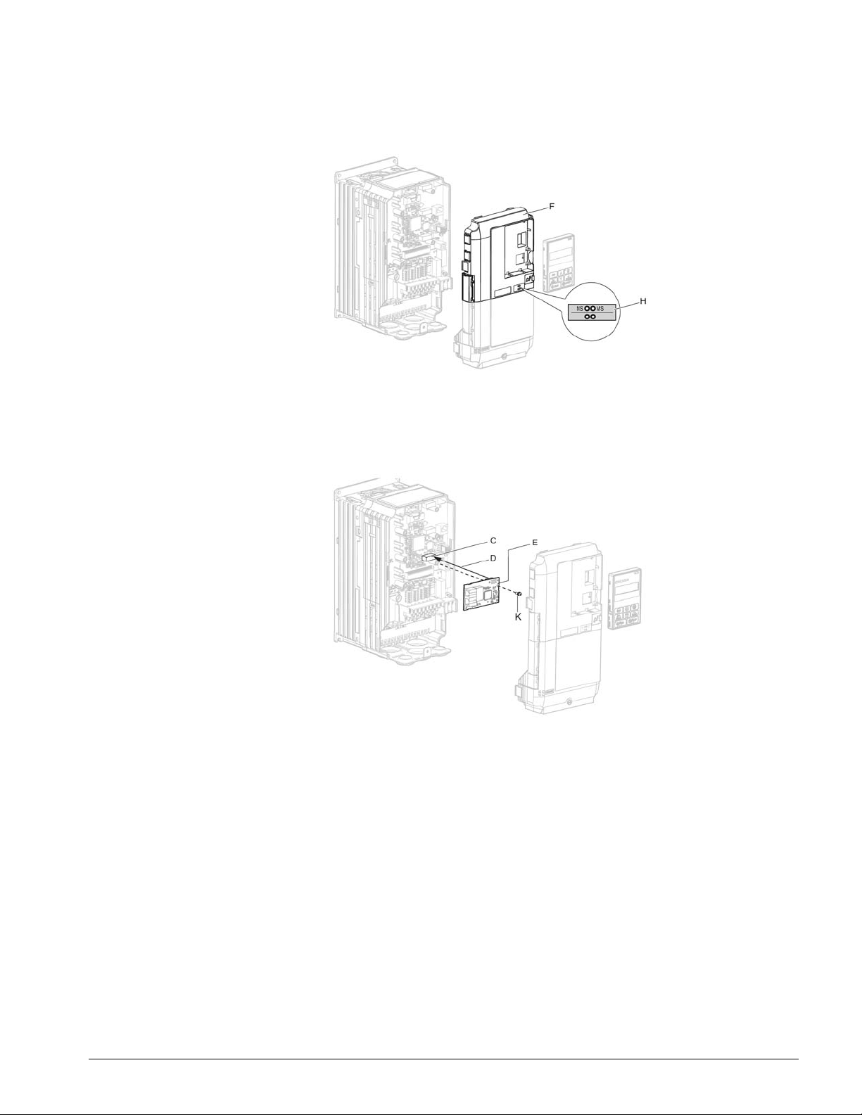
2. With the front covers and digital operator removed, apply the LED label (H) in the appropriate
position on the drive top front cover (F).
Figure 4: Apply the LED Label
3. Insert the option (E) into the CN5-A connector (C) located on the drive and fasten it using one of
the included screws (K).
Figure 5: Insert the Option
IMPULSE®•G+/VG+ Series 4 Profinet Installation Manual - August 2014
16
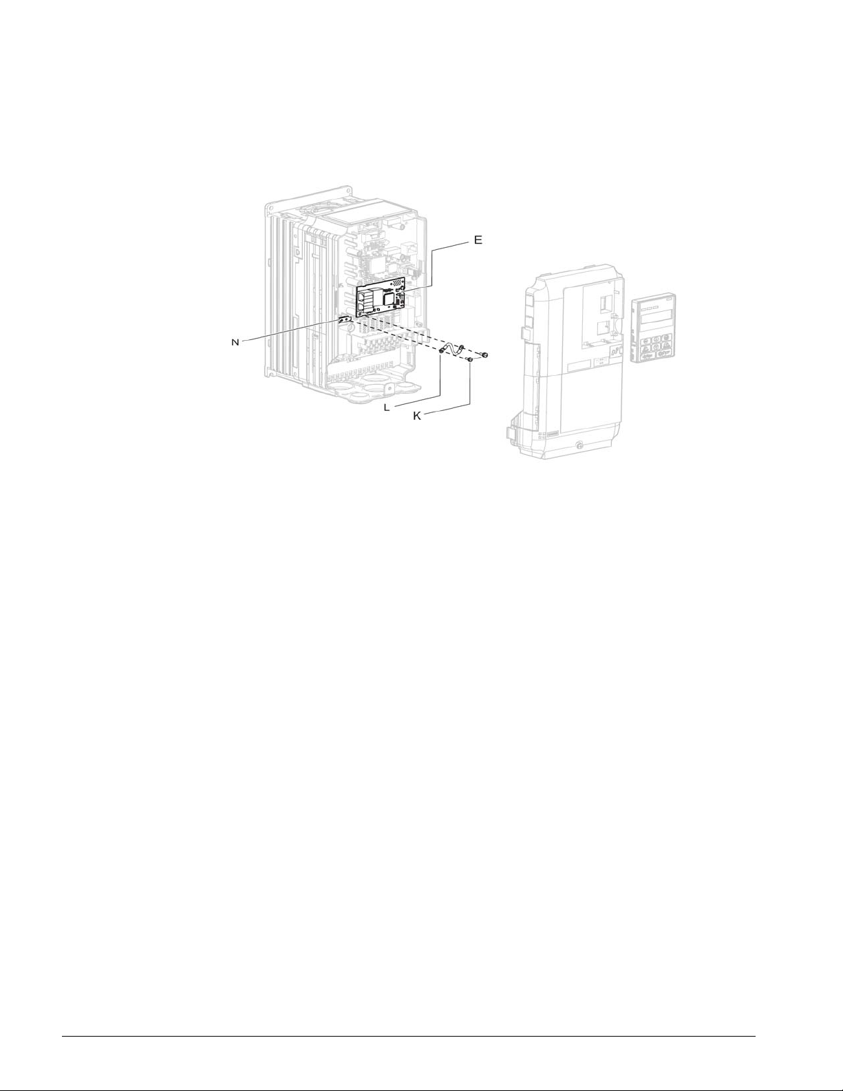
4. Connect the ground wire (L) to the ground terminal (N) using one of the remaining provided
screws (K). Connect the other end of the ground wire (L) to the remaining ground terminal and
installation hole on the option (E) using the last remaining provided screw (K) and tighten both
screws to 0.5 ~ 0.6 nm (4.4 ~ 5.3 in lb.).
Figure 6: Connect the Ground Wire
NOTE: There are two screw holes on the drive for use as ground terminals. When connecting
three options, two ground wires will need to share the same drive ground terminal.
IMPULSE®•G+/VG+ Series 4 Profinet Installation Manual - August 2014
17
Wiring the Option
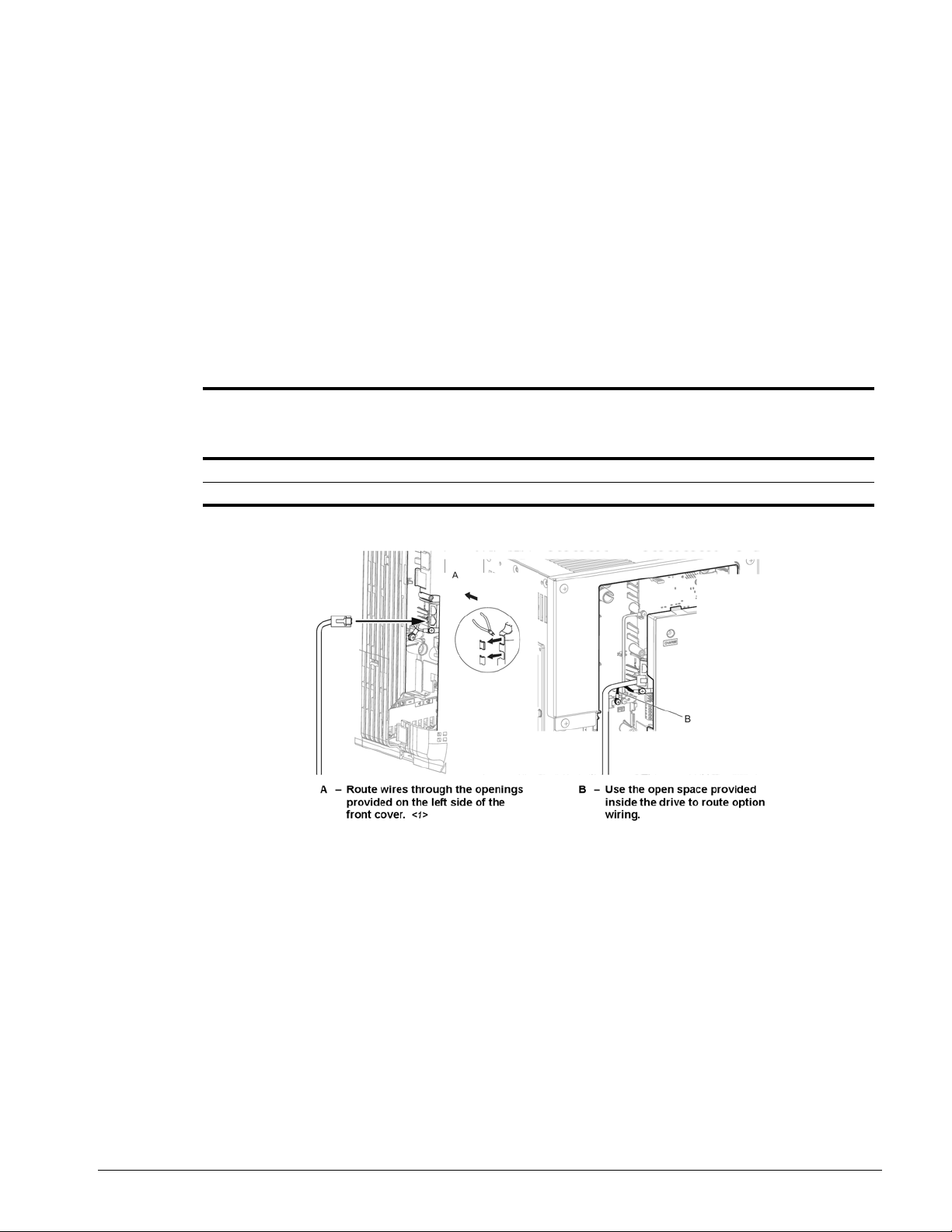
5. Route the option wiring.
Depending on the drive model, some drives may require routing the wiring through the side of the
front cover to the outside to provide adequate space for the wiring. In these cases, using diagonal
cutting pliers, cut out the perforated openings on the left side of the drive front cover. Sharp edges
along the cut out should be smoothed down with a file or sand paper to prevent any damage to the
wires.
5.a. Route the PROFINET CAT5e cable inside the enclosure for drives that do not require routing
through the front cover. Refer to Table 4: Mode l-Specific Cable Routing and Figure 7 to determine
the proper wire routing by drive model.
Table 4: Model-Specific Cable Routing
Wire Routing <1>
Drive Series Model
G+/VG+ S4 2003 to 2033; 4001 to 4018; 5001 to 5009 Figure 7 (A) -G+/VG+ S4 2047 and above; 4024 and above; 5012 and above -- Figure 7 (B)
Through Front
Cover
Inside Drive
<1> The drive will not meet NEMA Type 1 requirements if wiring is exposed outside the enclosure.
Figure 7: Wire Routing Examples
6. Connect the PROFINET CAT5e communication cable to the option connector (CN1) port 1.
To connect the option to a network, firmly connect RJ45 8-pin Shielded Twisted Pair CAT5e cable(s)
into the modular connector ports (see Figure 7).
NOTE: Do not connect or disconnect the communication cable while the drive is powered up or
while the drive is in operation. Failure to comply may cause a static discharge, which will
cause the option card to stop working properly. Cycle power on the drive and option card
to reestablish functionality.
IMPULSE®•G+/VG+ Series 4 Profinet Installation Manual - August 2014
18
 Loading...