

Page 1

-,
r------------*----------..,
NAVSHIPS
900,853
INSTRUCTION
BOOK
for
SPEAKER-AMPLIFIER
NAVY
TYPE
CMX
49545
Ma,mfactrtred for
U.
S.
NAVY DEPARTMENT
BUREAU OF SHIPS
6,
THE MAGNAVOX COMPANY
Fort Wayne, Indiana
I--_____
-----*----------~
Page 2

r----------------------*---------------------,
NAVSHIPS
900,853
INSTRUCTION
BOOK
for
SPEAKER
-AMPLIFIER
NAVY
TYPE
CMX
49545
lHallufaClm'ed
for
U.
S.
NAVY
DEPARTMENT
BUREAU
OF
SHIPS
by
THE
MAGNAVOX
COMPANY
Fort
Wayne,
Indiana
L-
_____________________
*
____________________
~
CONTRACT
NXsr
93879
Approved 1
JULY
1946
Page 3
NAV5HIP5
900,853
Front
Matter
A
Page 4

c
,
Front
Matter
NAVSHIPS 900,853
~DDRESG
NAvY DEPARTMENT.
BURPU
OF
SHIpS
NAvY
DEPARTMENT
Section
993-10
0
RD"ER
TO
FlU;:
NO.
BUREAU
OF
51-UPS
WASHINGTON
25.
D.
Co
ORIGINAL
27
June
1946
To,
All
Activities
concerned
with
the
Installation,
Operation
and
Maintenance
of
the
subject
"Equipment.
SUDj'
Instruction
Book
for
Speaker-Amplifier
Navy
Type
CMX-49545 (NAVSRIPS
900,853).
1.
NAVSRIPS
900,853
is
the
instruction
Dook
for
the
sUDje
ct
equipment
and
is
in
effect
upon
receipt.
2.
When
superseded
DY a later
edition,
this
publication
shall
be
destroyed.
3.
Extracts
from
this
pUDlication
may
be
made
to
facilitate
the
preparation
of
other
Navy
instruction
books
and
handbooks.
4.
Copies
of
this
pUDlication
may
be
oDtained
from
the
nearest
ElectronicS
Officer.
E.
L.
cocRIWIE
Chief
of
Bureau
"",,,
BUREAU
OF
sHIPS.
NAVV
DEPARTMENT.
WASHINGTON
2'.
D.
C.
B
Page 5
NAVSHIPS 900,853
Front
Matter
Change
No.
Dale
Signature
of
Officer
Making
Correction
.,
c
Page 6
NAVSHIPS
900,853
TABLE
OF CONTENTS
Paragraph
Contractual Guarantee
Report
of
Failure
SECTION
I - General Description
Suh;ect
Page
. . . . . . . . . . . . . . . . . iii
iv
I-I
1 Function .
..........
.
.....................................
I-I
I-I
I-I
I-I
I-I
2
3
4
5
Reference Data
Equipment Supplied
Equipment
Required But
Not
Supplied
Vacuum Tube Complement
...
SECTION
II-
Theory
of
Operation
I
Theory
of
Operation
SECTION
III
- Installation
and
Initial Adjustments
2
3
Unpacking
Installation
Initial Adjustments
.....
SECTION
IV -Operation
2-0--2-1
.................................
2~
3-0--3-1
4-0
3-0
3-0
3-1
1 Operation .
.............................................
.
4-0
SECTION
V - Maintenance
5-0--5-11-5-12
1 Operators Maintenance
..............
5-1
2
3
Preventive Maintenance
Corrective Maintenance
.......................................................
5-1
5-1
SECTION
VI
- Parts
and
Spare Parts Lists
......................................
6-1----{)-8
Page 7

NA
VSHIPS
900,853
LIST OF ILLUSTRATIONS
Figure
1·1
Speaker.Amplifier CMX·49545
................................................
.
1·0
4-1 Lower Front Panel
...........................................................
.
.w
5·1 Speaker.Amplifier CMX·49545 -
Top
Chassis View
..............................
.
5·2
5·2 Speaker.Amplifier CMX·49545 - Lower Chassis View
............................
.
5'3
5·3 Speaker.Amplifier CMX·49545 - Lower Chassis View
............................
.
5-4
5-7 Parts For Cone Replacement
..................................................
. 5·9
5·8 Completed Cone Replacement
.................................................
. 5·9
LIST OF
DRAWINGS
Figure
Page
2·1 Functional Block
Diagram
....................................................
.
2·1
3·1
Main
Terminal
Board
Diagram
................................................
3·0
5·4
Audio
Frequency Curve
.......................................................
5·5
5·6
5·7
5·5
5·6
5·9
Cable Connection Diagram
Schematic Circuit Diagram
Amplifier
Wiring
Diagram
..............................................
5·11-5·12
LIST OF
TABLES
Table No.
6·1
Major
Unit
.........................................................
.
6·2
6·3
Combined Parts
and
Spare Parts Lists by Symbol Designations
List
of
Parts by
Navy
Numbers
................................................
.
6-4 Applicable Resistor Color Codes
..............................................
.
6·5 Applicable Capacitor Color Codes
.............................................
.
6-6 List
of
Manufacturers
.......................................................
.
Pllge
6-1
6-1
6·4
6·6
6·7
6-8
,
•
•
Page 8
•
•
NAVSHIPS 900,853
CONTRACTUAL
GUARANTEE
The
Contractor
guarantees
that
at
the
time
of
delivery
thetof
the
articles
provided
for
under
this
contract will
be free
from
any defects
in
material
or
workmanship
and
will
conform
to
the
requirements
of
this
contract. Ex-
cept as
to
vacuum tubes, batteries,
rubber
and
material
normally consumed
in
operation,
the
equipment, includ-
ing
all spare parts, is
guaranteed
for a period
of
one
year
from
the
date
of
its delivery
to
and
acceptance
by
the
Government,
with
the
understanding
that
all items
found
to
be defective as
to
material,
workmanship
or
manufacture will be repaired
or
replaced, f.a.b. any
point
within
the
continental
United
States designated
by
the
Government,
without
delay
and
at
no
expense
to
the
Government;
provided,
that
such
guarantee
shall
not
obligate
the
Contractor
to
repair
or
replace any
such defective items unless
the
defect appears
within
the
aforementioned
period
and
the
Contractor
is noti-
fied
within
a reasonable time
and
unless
the
defect
is
not
the
result
of
normal
expected shelf life deteriora-
tion.
This
guarantee
shall
then
continue
as
to
corrected
or
replacing articles
or,
if
only
parts
of
such are cor-
rected
or
replaced,
to
such corrected
or
replacing parts,
until
one year
after
the date
of
redelivery.
To
the
extent
the
equipment,
including
all parts
and
spare parts, as defined above,
is
of
the
Contractor's
de-
sign
or
is
of
a design selected
by
the
Contractor,
it
is
also guaranteed, subject
to
the
foregoing
conditions,
against defects
in
design,
with
the
understanding
that
if
ten percent
or
more
of
the
total
quantity
comprising
such item furnished
under
the
contract
(but
not
less
than
two
thereof)
is
found
to
be
defective as
to
design,
the
entire item
will
be conclusively presumed to
be
of
defective design
and
shall
be
subject
to
one
hundred
percent correction
or
replacement by a suitably rede-
signed
item.
All defective items will be subject
to
ultimate return
to
the
Contractor
except
that
the
exigencies
of
the
naval
service may necessitate expeditious repair
of
certain
items in
order
to
prevent
extended
interruption
of
com-
munications
and
in
such cases
the
return
of
the defec-
tive items
for
examination by
the
Contractor
prior
to
repair
or
replacement shall be mandatory.
The
report
of
a responsible authority, including details
of
the
con-
ditions
surrounding
the
failure,
will
be acceptable as a
basis
for
effecting expeditious
adjustment
under
the
provisions
of
this contractual guarantee.
If
the
Government
does
not
require correction
Or
re-
placement
of
a defective
or
nonconforming
article, the
Contractor,
if
required by the contracting officer within
a reasonable time after
the
notice
of
defect
or
noncon-
formance, shall repay such
portion
of
the
contract price
as
is
equitable
in
the circumstance. Equitable
in
the cir-
cumstance is
to
be determined by mutual agreement be-
tween
the
Contractor
and
the
contracting officer. Failure
to
agree
to
such
adjustment
shall be a dispute concerning
a question
of
fact
within
the
meaning
of
the
section
of
this contract
entitled
"Disputes".
iii
Page 9
iv
NAVSHIPS 900,853
REPORT OF FAILURE
Report
of
failure
of
any
part
of
this equipment,
during
its service life, shall be
made
to
the Bureau
of
Ships
in
accordance
with
current
instructions.
The
report
shall cover all details
of
the
failure and
give
the
date
of
installation
of
the equipment.
For
procedure
in
reporting
failures see
Chapter
67
of
the
Bureau
of
Ships
Manual,
or
superseding instructions.
CONTRACT:
NXsr
93879
DATE
OF
CONTRACf: 2 APRIL
1945
SERIAL
NUMBER
OF
EQUIPMENT
___________________
_
DATE
OF
ACCEPTANCE
BY
THE
NAVY
________________
_
DATE
OF
DELIVERY
TO
CONTRACf
DESTINATION
____________
_
DATE
OF
COMPLETION
OF
INSTALLATION
______________
_
DATE
PLACED
IN
SERVICE
_____________________
_
Blank
spaces
in
this
book
shall
be
filled in at time
of
installation.
Operating
personnel shall also
mark
the
"date
placed
in
service"
on
the
date plate located below
the
model nameplate
on
the
equip.
ment, using suitable methods
and
care
to
avoid
damaging
the equipment.
All requests
or
requisitions
for
replacement material
should
include the
following
data:
1.
Name
of
part
desired.
2.
Navy
stock
number
or,
when
ordering
from
an
Army supply depot,
the
Army stock number.
If
the
Navy
stock
number
has
not
been assigned,
the
requisitions
should
specify the following:
1.
Equipment
model designation.
2.
Name
of
part
and
complete description.
3. Manufacturers designation.
4. Contractors
drawing
and
part
number.
5. A WS,
JAN,
or
Navy
type designation.
SAFETY
NOTICE
The
attention
of
officers
and
operating
personnel
is
directed
to
Chapter
67
of
Bureau
of
Ships Man-
ual
or
superseding instructions
on
the
subject
of
Radio-Safety precautions
to
be observed.
l'
•
Page 10

Page 11

NAVSHIPS
900,853
)
Fi!lure
I-I
5
< •
peaker-Amp/ifier
-
Navy
Type
CMX
49545
1-0
Page 12
r
General
Description
NAVSHIPS
900,853 Section 1
Paragraphs
1-5
SECTION
I
GENERAL
DESCRIPTION
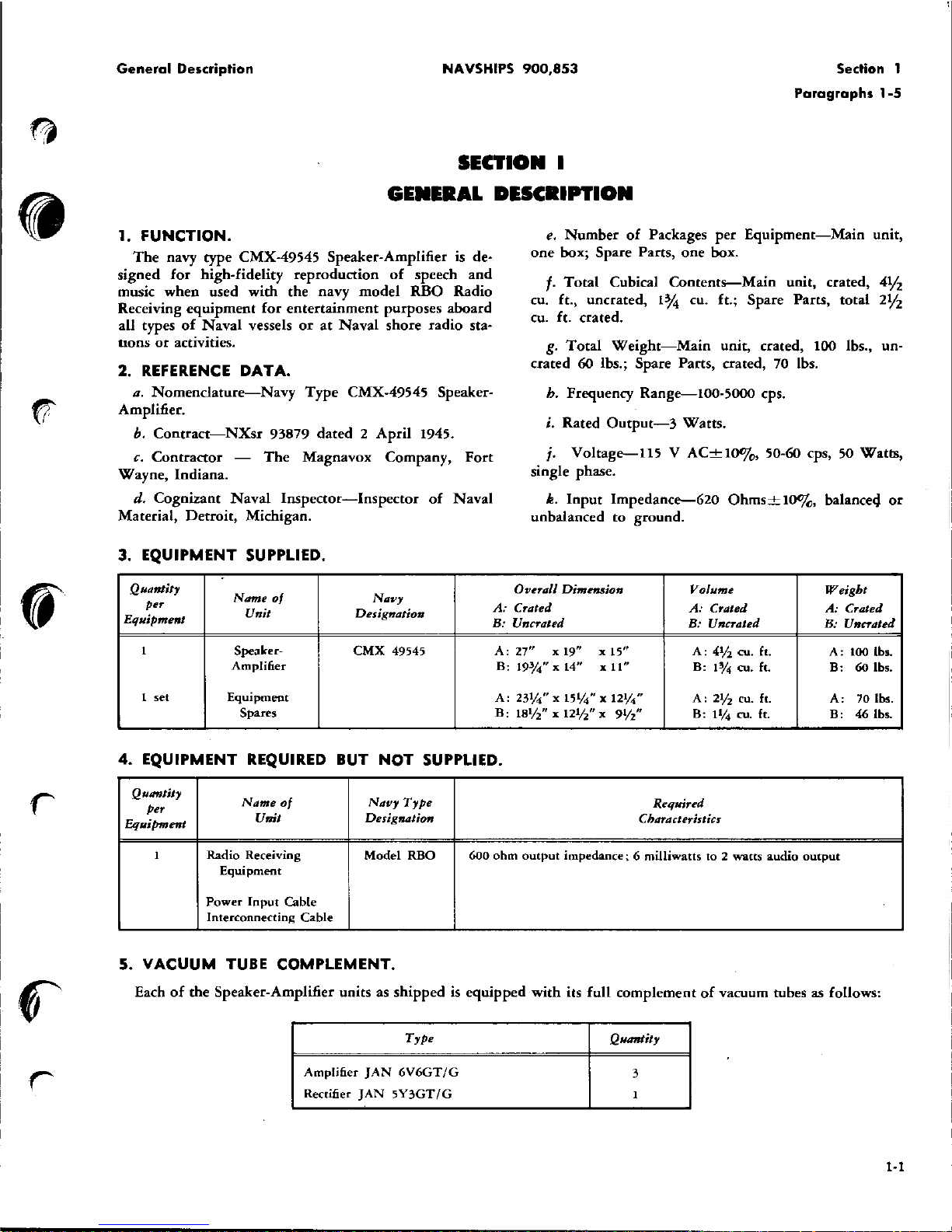
1.
FUNCTION.
The
navy type
CMX·49545
Speaker.Amplifier is de-
signed
for
high-fidelity
reproduction
of
speech
and
music
when
used
with
the
navy
model
RBO
Radio
Receiving
equipment
for
entertainment
purposes
aboard
all types
of
Naval
vessels
or
at
Naval
shore
radio
sta-
nons
or
activities.
2.
REFERENCE
DATA.
a.
Nomenclature-Navy
Type
CMX·49545 Speaker·
Amplifier.
h.
Contract-NXsr
93879
dated 2 April
1945.
c.
Contractor
-
The
Magnavox
Company,
Fort
Wayne,
Indiana.
d.
Cognizant
Naval
Inspector-Inspector
of
Naval
Material,
Detroit,
Michigan.
3. EQUIPMENT SUPPLIED.
Quantity
per
Name
0/
Navy
Unit
e.
Number
of
Packages
per
Equipment-Main
unit,
one
box; Spare Parts, one box.
f.
Total
Cubical
Contents-Main
unit, crated,
4Vz
Cll.
ft.,
uDerated,
1%
cu.
ft.;
Spare Parts,
total
2¥2
cu. ft. crated.
g.
Total
Weight-Main
unit, crated, 100 Ibs.,
un-
crated 60 lbs.; Spare Parts, crated, 70 Ibs.
h.
Frequency
Range-100·5000
cps.
i.
Rated
Output-3
Watts.
j.
Voltage-1l5
V
AC±I00/
o
,
50-60 cps, 50
Watts,
single phase.
k.
Input
Impedance-620
Ohms±IO%,
balance4
or
unbalanced
to
ground.
Overall Dimension
Volume
Weight
A:
Crated
A:
Crated
A: Crated
Equipment
Designation
B: Uncrated
B: Uncrated
B: Uncrated
1 Speaker-
CMX
49545
A,
27"
x 19"
xIS"
A:
4%
cu. ft.
A,
100
lb
•.
Amplifier
B:
190/4" x 14"
x 11"
B:
1%
cu. ft.
B,
60 Ibs.
1 set
Equipment
A:
23%"
x 15lj4" x 12lj4"
A:
2%
cu. ft.
A,
70 lbs.
Spares
B:
18lj2" x
12%"
X
9lj2"
B:
11;4
cu. ft.
B,
46
lb
•.
4.
EQUIPMENT REQUIRED BUT
NOT
SUPPLIED.
Qutmtity
Name
0/
Navy
Type
Required
per
Equipment
Unit
Designation
Characteristics
1 Radio Receiving
Model
RBO
600
ohm
output
impedance; 6 milliwaus
to 2 watts
audio
output
Equipment
Power
Input
Cable
Interconnecting
Cable
5.
VACUUM
TUBE COMPLEMENT.
Each
of
the
Speaker. Amplifier units as
shipped
is
equipped
with
its full
complement
of
vacuum tubes as follows:
Type Quantity
Amplifier
JAN
6V6GT/G
3
Rectifier
JAN
SY3GT/G
1
1·1
Page 13

Section 2
Paragraph
1
NAVSHIPS
900,853
Theory
of
Operation
SECTION
II
THEORY OF OPERATION
I.
The
CMX·49545
SPEAKER·AMPLIFIER
consists
of
a two-stage
audio
amplifier
with
power
supply,
and
a magneto-dynamic loudspeaker, all contained
in
a cast
aluminum case.
The
amplifier consists
of
a voltage-amplifier stage
using a
JAN
6V
GGT
/G
vacuum tube; a
push.
pull
class
"AU
power
output
stage using
two
JAN
6V6GT/G
vacuum tubes;
and a power
supply using a JANSY3-
GT
/G
high·vacuum rectifier tube,
and
furnishing
all
filament, plate,
and
grid
voltages necessary
for
opera-
tion
from
115 volt, 60 cps, single phase
alternating
current
power
lines.
Figure 2-1 is a functional block diagram
of
this
equipment.
The
amplifier
unit
is
arranged
to
select
anyone
of
five 600
ohm
input
channels by
the
proper
setting
of
the
channel selector switch (S-102) which is adjustable
from
the
front
of
tbe
panel.
The
unused channels are
terminated
with
resistors
(R-I0l
to
R-I05,
incl.).
The
input
to
the
grid
of
the
voltage-amplifier tube
(V.101)
is
variable by means
of a potentiometer
(R·106)
having a logarithmic taper, which may
be
adjusted
from
the
front
of
the
panel
to
give
the
desired
audio
output.
The
tuned-filter type
tone
control
circuit
is
inserted
2-0
between the voltage amplifier
and
the
power
amplifier
and
the
tone may be regulated by means
of
a potentiom-
eter
(R·112),
adjustable
from
the
front
of
the
panel,
to
give
the
des_ired
audio response.
The
tone
control
circuit
is
composed
of
an
inductance
(L-I02),
three
capacitors
(C-108, C·109,
and
C·ll0),
and
the
potentiometer
(R·112).
The
power
amplifier stage incorporates a negative-
feedback circuit
(R.l13,
R·114, R.115, R·116,
GIll,
and
C-1l2)
to
give a better audio response
and
to
reduce
distortion.
The
power
supply stage
is
a conventional circuit
w-
ing
a high·vacuum rectifier tube
(V·104)
and
a single
PI-section inductance-capacitance
(L-I0l,
C-I07A,
and
C·107B) filter.
The
loudspeaker is a moving coil type speaker using
a
permanent
magnet
to
furnish
the
magnetic flux.
The
moving
coil has
an
impedance
of
3.7 ohms
at
1000
cps,
which
is matched
to
the
load
resistance
of
the
power
amplifier tubes by means
of a transformer
(T·103)
mounted
on
the
amplifier chassis.
The
cast aluminum case,
housing
the
amplifier
and
loudspeaker, forms a vented-bafile type acoustic chamber
for
improved reproduction
of
low-frequency tones.
•
Page 14

':'
~
...
,0.
e:
~
..
•
...
e:
~
~
ir
~
!!.
'"
0-
~
o
ir
~
.,
~
~
r--
...
---
_ ..
-_
..
FROM
G
V-101
...
INPUTS
I
~SOl
:
I i
II I6V6
-
GT
I.
_
1&
\
1_.
INPUT VOLUME
SELECTOR
OONTROL
S-102
R-10e
LEGEND:
ti-
~
STAGE
NS.
r-
L-l02
C-l01
T-l
C-l01
:
C-110
I
I
""---
TONE
OONTROL
R-Ut
r-
3
i.
VARIABLE OONTROLS ARE INDIOATED
BY
A OIROLE AND A DOTTED
LINE
SHOWING
POINT
IN
OIROUIT WHERE
THEY ARE OONNEOTED.
2_
LETTERS
AND
NUMBERS OUTSIDE TUBE
BLOOKS INDIOATE TUBE
ELEMENT
·AND
SOOKET PIN.
3_
HEAVY LINES AND
ARROW
HEADS
INDIOATE DIREOTION
OF
ENERGY
FLOW_
G
POWER
AMPLIFIER
V-102
P
'5
6V6-GT
IT
POWER
AMPLIFIER
G
V-103
P
"'i
eVe-GT
t'3
.,
INVERSE FEEDBAOK
•
.,
01
n
ER
,-
'"101
LS-iOi
~
SPEAKER AMPLIFIER
CMX-49545
FUNCTIONAL BLOCK DIAGRAM
...
:r
CD
0
-<
0
-
0
"
CD
~
Q
::
0
"
z
>
<
.,.
:J:
"
.,.
8
Go
'"
w
.,.
CD
~.
o
"
..
Page 15

Section 3
Paragraphs
1-2
NAVSHIPS 900,853 Installation
and
Initial Adjustments
SECTION
III
INSTALLATION
AND
INITIAL ADJUSTMENTS
1.
UNPACKING.
Each Speaker. Amplifier is shipped
in
completely
moisture·
proof
packing which consists
of
two separate
corrugated cardboard cartons, a moisture·
proof
bag,
desiccant, and
an
outer
wooden box. Care should he
exercised
in
removing
the
unit
from its containers
to
avoid severe jolts which
might
damage the vacuum
tubes installed
in
the unit.
Hooks
or
other
sharp
in·
struments which
might
damage the speaker cone should
not
be used.
2.
INSTALLATION.
This
equipment
is
amenable to either
bulkhead
or
table mounting.
For
bulkhead
mounting,
four
mount-
ing
holes are furnished
in
the back
of
the cabinet.
If
table installation is desired,
four
mounting
holes
may
be
drilled
where
"spotted"
on
the
bottom
of
the
cabinet.
Where
two
or
more units are installed
in
the same
compartment,
it
is
preferred
that
the units be placed
on
the same
bulkhead
and
spaced
in
such a
manner
that
each
unit
covers
an
equal deck area.
NOTE
The
installation
of
the Speaker-Amplifier units
should be limited to enclosed
~paces
offering
some degree
of
protection
from
gun
blast as
this
equipment
is neither
water.proof,
sub-
mergence-proof,
nor
blast.proof.
In
order
to
provide
for
the entrance
of
the
input
and
power
cables, bosses are furnished
on
each side
and
on
top
of
the cabinet in which holes may be drilled to fit
the cables. Side
or
top
entrance should be made ac·
cording
to
the convenience
of
installation.
After
the
input
cable,
containing
the
output
of
from one
to
five
stations from the central radio receiving equipment, has
been introduced
to
the
cabinet, connections should be
made
to
the
input
terminals indicated
in
figure 3·1.
If
the
output
of
the
central radio receiving equipment
incorporates a balanced line, a
jumper
wire should be
placed from terminal
#
12
(input
center
tap)
to
termi-
nal
#7
(ground).
Power connection from a 115 V
AC
line cable is then
made
to
terminals
#)
3
and
# )4.
NOTE
This Speaker. Amplifier is designed
to
operate
ONLY
when connected
to a II
5 volt 60 cps
single phase AC
power
source.
DO
NOT
con·
nect to a
DC
power
source as the line fuses
(F·JO)
and
F·J02)
will
burn
out
under
these
conditions,
and
damage to
the
power
trans-
former
(T.)04)
may result.
A direct lead
from a good
ground
shall be connected
to
terminal #
7,
which serves as the circuit
ground
for
this equipment.
Figure
J-J.
Main Terminal Board Diagram
3·0
Page 16

Installation
and
Initial Adjustments
NAVSHIPS
900,853 Section 3
Paragraphs
2-3
The
equipment
is
so designed
that
no
additional
bonding,
shielding,
or
grounding
is
required except as
noted
in
the
preceding
paragraph.
No
cables
for
the
required external connections be-
tween this
equipment
and
the
power
line,
ground,
and
the
companion
receiver
or
receivers are furnished, either
in assembled form
or
as
bulk
parts.
The
external cabling
should
he installed in
the
most
convenient
manner
commensurate
with
the least pos-
sible
power
loss
or
voltage
drop
in
the lines,
and
mini-
mum
noise pick.up in
the
input
circuit connections.
3.
INITIAL
ADJUSTMENTS.
Adjust
the
output
of
the
companion radio receiver
or
,eceivers
(Navy
Type
RHO
or
equivalent) so
that
the
input
to
any Speaker· Amplifier will be
within
the
range
of
6 milliwatts (1.9 volts across 600
ohms)
to
2 watts (34.7 volts across 600
ohms)
for
proper
operation
of
the
Speaker· Amplifier.
The
input
selector
on
the
outside
of
the
front
panel is adjusted to select
a total
of
five inputs.
1£
less
than
five
input
circuits
are to be used, the switch stop must be adjusted so
that
the
number
of
switch positions will correspond
with
the
number
of
input
circuits connected
to
the
amplifier.
To
reset the
stop
on
the
input
selector
switch, first, remove
knob
from
the
switch shaft; second,
remove
the
switch
mounting
nut
and
pull
switch from
opening
in
panel
(inside);
third,
turn
the
stop plate
(with
stop
pin
attached)
until
placing stop
pin
in locat-
ing
hole will give
the
number
of
input
positions desired;
and
finally, replace switch
in
panel, secure
with
mount-
ing
nut,
and
replace switch knob.
3-1
Page 17

Section 4
Paragraphs
1-2
NAVSHIPS
900,853
Operation
SECTION IV
OPERATION
1.
This
Speaker. Amplifier is designed
to
furnish the
rated three watts
of
audio power to the integral loud-
speaker with a power input--to the amplifier
of
6 milli-
watts (1.9 volts across 600
ohms)
to
2 watts (34.7 volts
across 600 ohms). An input
of
less than 6 milliwatts
may result in insufficient sound output, and
an
input
of
more than 2 watts may result in overloading with
objectionable distortion
of
the sound output. (See para-
graph
III·3)
2.
To
operate
the
Speaker-Amplifier
after
complete
installation has been made, move the "OFF-ON" switch
(figure 4-1)
to
the
"ON"
posItIon
and
set the channel
selector switch to the desired station. The volume con-
trol
on
the
right
side
of
the
panel should then be set
to the desired volume which increases with the scale.
Finally, the
tone
control
on
the left
of
the
"OFF-ON"
switch should be set to give the desired tone.
It
will be
noted that the minimum attenuation
of
the high frequency response occurs with the knob in the most clockwise position.
It
follows that the attenuation
of
the
high frequency response increases
as
the knob
is
turned
counterclockwise.
n,
<~.
•.••. _
_
t"~"
••
~".'''
""_
.-.-
'"'---:.-=
~
~
.
Figure
4-
J.
Lower
front
Panel
4-0
I~
I~
Page 18

~-----.---------.----,-
--=--~-----
Operation
NAVSHIPS
900,853
Section 4
4-1
Page 19

Section 5
NAYSHIPS 900,853
Maintenance
5-0
FAILURE REPORTS
A
FAILURE
REPORT
must
be
filled
out
for
the
failure of
any
part
of
the
equipment
whether
caused
by
defective
or
worn
parts,
improper
operation,
or
external influences.
It
should
be
made
on
Failure
Report, form NBS-
383,
which
has
been
designed
to simplify this
requirement.
The
card
must
be
filled
out
and
forwarded
to
BUSHIPS
in
the
franked
envelope
which
is
provided.
Full
instructions
are
to
be
found
on
each
card.
Use
great
care
in filling
the
card
out
to
make
certain
it carries
adequate
infonnation.
For
example,
under
"Circuit
Symbol"
use
the
proper
circuit identification
taken
from
the
schematic
drawings, such
as
T -803, in
the
case
of a transformer,
or
R-207, for a resistor.
Do
not
substitute
brevity
for clarity. Use
the
back
of
the
card
to
completely describe
the
cause
.u
..... u .....
H
...
W,,",H'.O"".,~,
~.
of
failure
and
attach
an
extra piece
of
paper
if necessary.
The
purpose
of this
report
is to inform B U-
SHIPS of
the
cause
and
rate
of failures.
The
inrormation
is
used
by
the
Bureau
in
the
design
of
future
equipment
and
in
the
maintenance
of
adequate
supplies to keep
the
present
equip-
ment
going.
The
cards you send in,
together
with
those from
hundreds
of
other
ships, fur-
nish a store
of
information
permitting
the
Bureau
to
keep
in
touch
with
the
performance
of
the
equipment
of
your
ship
and
all
other
ships of
the
Navy.
This
report
is
not
a requisition. You
must
re-
quest
the
replacement
of parts
through
your
Officer-in-Charge in
the
usual
manner.
Make
certain you
have a supply
of
Failure
Report
cards
and
envelopes
on
board.
They
may
be
obtained
from
any
Electronics Officer.
.........
>GO
..
,.
............
'.
_
.......
_---
...
-
NAVY
DEPARTMENT
BUREAU
OF
SHIPS
WASHINGTO~!!5.
D.
C
.l
._
19cJd;·lq4~
Sample
Failure
Report
Cards Properly Filled
In
Page 20

r
Maintenance
NAVSHIPS
900,853
Section 5
Paragraphs
1-3a
SECTION
V
MAINTENANCE
1. OPERATORS
MAINTENANCE.
The
only
maintenance
required
of
the
operator
is:
a.
REPLACING
BURNED·OUT
PILOT
LAMP
(REPLACEABLE
FROM
FRONT
OF
PANEL).
(1)
Unscrew
and
remove
the
red
jewel assembly.
(2)
Remove
the
defective
pilot
lamp.
(3)
Insert a new
Mazda
51
or
equivalent
pilot
lamp.
(4)
Replace jewel assembly.
h.
REPLACING
DEFECTIVE
VACUUM
TUBE.
(1)
Throw
"ON·OFF"
switch
to
"OFF"
position.
(2)
Open
the amplifier case.
(3)
Remove
the
defective tube.
Remove
tuhe
with
a
straight,
upward
pull.
DO
NOT
move tube from side
to
side as this may result
in
the base key
breaking
off
and
remaining
in
the socket.
(4)
Replace
with
proper
type tube.
(5)
Close the amplifier case.
IN
ORDER
TO
OBTAIN
FULL
TUBE
LIFE
AND
PROPER
OPERATION,
DO
NOT
USE
TUBES
OF
OTHER
TYPES
THAN
THOSE
HEREIN
SPECIFIED.
ALL
TUBES
FURNISHED
AS
INITIAL
SUPPLY
OR
SPARES
SHALL
BE
USED
PRIOR
TO
EMPLOY·
MENT
OF
TUBES
FROM
GENERAL
STOCK.
e.
REPLACING
BLOWN
FUSES.-DO
NOT
RE·
PLACE
UNTIL
THE
DEFECT
CAUSING
THE
FUSE
TO
BLOW
HAS
BEEN
ISOLATED
AND
COR·
RECTED.
(I)
Throw
"ON·OFF"
switch to
"OFF"
position.
(2)
Open
the amplifier case.
(3)
Remove
blown
fuse
from
fuse
hoard
located
on
back
panel
of
amplifier
case.
CAUTION
Equipment
"On-Off"
switch does
not
remove
the
power
from
the fuses.
The
fuse clips
at
the
top
of
the fuse
board
have a
potential
difference
of
115 volts
AC
between
them
at
all times. Use due
precaution
in
removing
the defective fuse.
(4)
Insert
new fuse
Type
3AG,
1.0 ampere.
(5)
Close
the
amplifier case.
2.
PREVENTIVE
MAINTENANCE.
Operator
shall be
guided
by
Chapter
67
of
the
"Bureau
of
Ships
Manual".
Vacuum
tubes
(V·IOI,
V·102, V·103,
and
V·104)
sh.ll
be checked
on a standard
tube checker
after
every 250
hours
of
operation
or
every three
months,
whichever
comes first. Defective tubes shall be replaced. immediately
for
most
efficient
operation
(See
paragraph
Ib
of
Section
5).
The
dry
electrolytic capacitors (C-101
and
C-102) are
used as cathode
by-pa~s
capacitors,
and,
under
normal
conditions
of
operation,
have sufficient safety factor to
insure a life expectancy equal to
that
of
the entire equip-
ment.
The
balance
of
the
components
in
this
equipment
are
not
subject to
deterioration
due
to
operation,
and
need
to
be checked
only
in
case
of
equipment
failure (See par-
agraph 3 of
Section 5
on
"Corrective
Maintenance").
3.
CORRECTIVE
MAINTENANCE.
If
any
major
repairs
or
replacements become neces-
sary, it is recommended
that
such repairs
or
replace-
ments
be
made
in
a well
equipped
shop
where the
proper
tools,
measuring
equipment,
and
personnel are
available.
Before
making
any repairs
or
adjustments
in
the
Speaker-Amplifier,
it
should
be definitely ascertained
that
the
difficulty
being
experienced is
not
the result
of
external
or
deteriorating
influences such as
worn
out
tubes,
improper
operating
voltages,
blown
fuses,
exterior
noises, etc.
Over-
and
under-chassis views (figures 5-1, 5-2,
and
5-3)
show
the
location
of
tubes
and
other
parts
of
the
Speaker· Amplifier.
Figure 5-4 shows a typical
audio
frequency response
curve,
and
may
be used
in
checking the
over~all
perform-
ance
of
the amplifier if
the
required
audio
oscillator
and
output
meter
is available.
Following
is a suggested systematic procedure
of
"trouble-shooting"
malfunctions
of
the
equipment:
a.
If
the
equipment
does
not
operate
when
the
switch
is
moved
to
the
"ON"
position:
(I)
Check the
power
supply
to
make sure
that
the
source is
11 5 volt
AC
60 cps.
(2)
Check
the
fuses.
(3)
Check
the
circuit
continuity
through
the cables.
(see figures 3·1
and
5·5).
5-1
Page 21

Section 5
NAVSHIPS 900,853
Maintenance
figure
5-1.
Speaker-Amplifier
CMX-49545
Top
Chassis
View
I~
5·2
Page 22

Maintenance
('>II
NAVSHIPS
900,853
RESISTOR BOARD
(SEE
FIG.5-5)
RESISTOR
BOARD
(SEE
FIG.
5-5)
Figure
5·2.
Speaker.
Amplifier
CMX·49545
Lower
Chassis
View
Section 5
5·3
Page 23

Section 5
RESISTOR BOARD
(SEE
FIG.5-5)
NAVSHIPS
900,853
Maintenance
RESISTOR, BOARD
(SEE
FIG.5-5)
Figure
5-3.
Speaker-Amplifier
CMX-49545
Lower
Chassis
View
5-4
•
•
•
Page 24

Maintenance
NAVSHIPS 900,853
Section 5
figure
5-4.
Audio
frequency
Curve
5-5
Page 25

Section 5
NAVSHIPS 900,853
Maintenance
Figure
5-5.
Cable
Connection Diagram
5-6
Page 26

...
cO'
C
~
..
'"
,
~
'"
"
:r
It
ii
D
::-.
"
!:!
~
"
~
to
,i"
CD
~
D
ii
vo
..:..
-,
-"
..
"
~
z
L 2
3
..
"
~
z
..
4
..
..
"
~
;!;
,:,
7
~
f 8
..
•
i
z
..
G
'~
•
"~
GROUND
qa::
..
",
"'-
Go
::~
J
T-104
'-101
6V6-G
V-lOl
5Y3-G
y-t04
-,.
0
1-101
<
o
o
~
•
L-I01
00001
220.1\.
7
2
1
2
-
-
c
1
;)
•
...I
V-l03
6V6-G
.02MFD.
NOTE-
n
C,
VOLTAGES MEASURED BETWEEN
GROUND
AND
INDICATED
TERMINALS,
USING 1000 OHMS/VOLT METER.
FILAMENT
VOLTAGE
MEASURED
BETWEEN
SOCKET TERMINALS
USING
1000 OHMS/VOLT
RECTIFIER
TYPE
A.C.
METER.
VOLTAGES
MEASURED
WITH
115V.
60
CPS
LINE
VOL.TAGE.
RESISTANCE MEASURED WITH EQUIPMENT
-OFF-
a.
EXTERNAL
CABLES
DISCONNECTED.
RESISTANCE
VALUES
DESIGNATED
(6)
DENOTE
RESISTANCE
TO
GROUND
OF
INDICATED POINT.
VOLTAGE a RESISTANCE VALUES MEASURED
WITH
WESTON
MODEL
772
ANALYZER.
3:
D
:r
;;
" D
"
"
..
z
S
X
:;
lit
J
e:
...
¥'
~
o
"
III
Page 27

Section 5
Paragraphs
3a-3b(3)
NAVSHIPS
900,853
Maintenance
(4)
Check the tubes
to
see
that
they light,
and
if
necessary replace
with
known
good
ones.
(5)
Introduce
an
audio signal
to
the
circuit
and
check to see where it stops.
h.
If
the
equipment
operates
but
operates poorly:
(1)
With
equipment switched
"ON"
and
115 volt
single phase
60 cps
AC
applied
to
the
power
terminals,
check
component
voltages against the voltages shown
in
figures 5-6
and
5-9.
(2)
With
equipment
switched
"OFF",
volume
control set at
10,
tone
control set at
10,
and
all external
cables disconnected, check resistance
to
ground
of
com-
ponents
against
the
resistance values
shown
in
figures
5-6
and
5-9.
(3)
Check the loudspeaker
for
poor
connections
and
for
dirty
or
sticky voice coil.
If
the
cone
and
voice coil assembly
is
found
to
be
defective, replace-
ment
may be made by using Cone
and
Voice Coil As-
sembly
#16C50G2,
which
is
furnished
with
the
spare
parts,
and
adhering
to
the
following
instructions:
(a)
Remove the flexible moving coil leads
from
the
terminal strip by
the
application
of a hot
soldering
Iron.
(b)
Cut carefully
around
the edge
of
both
cone
and
corrugated
paper
spider so
that
the
entire moving
structure assembly may
be
removed at once.
(
c)
Im'mediately cover
the
air
gap
with
tape to
prevent
the
entry
of
iron
filings, etc.
(d)
Soften
th~
water-proof
cement which at-
tached
the
cone
and
spider
to
the
housing
with
lacquer
thinner
or
acetone. Use
thinner
liberally
and
in
a few
minutes wipe away all remains
of
the
paper
and
cement.
5-8
(e)
Then
remove all remains
of
the
paper
and
cement from the housing,
after
which remove the tape
and
blow
the
air
gap
with
compressed air
if
available,
or
wipe
out
with
a piece
of
Scotch tape.
(!)
Apply
evenly
an
ample supply
of
some
good
grade, fast drying water-proof cement
to
the hous-
ing
rim
and
in
the circular depression which seats the
spider (see figure 5-7).
Put
the
new assembly lightly in
place
with
the moving coil leads in correct position
to
be properly soldered to
the
terminal strip
and
with the
cone edge in contact
with
the housing rim ail
the
way
around. Immediately
then
slip the
0.006"
paper
spacer
(packed with the replacement cone assembly) curved
to
fit
around
the core between the inside
of
the moving coil
and
steel core.
Next,
apply
an
even coat
of
cement to
the
top
side
of
the
pulpboard
gasket
and
press lightly
in
place (see figure
5-8).
Take
care
not
to slide the cone
one
way
or
another
when
assembling the gasket. Make
certain
that
the
moving coil has entered the air gap
far
enough to place the rim
of
the
spider in good contact
with
the housing, yet
not
so far
as
to
seriously depress
the
spider in its center section.
(g)
Place
the
assembly
on
a smooth, flat surface
(gasket
down)
with
a small weight
on
the back and allow
to
become
thoroughly
dry before proceeding (approxi-
mately 30 minutes).
(
h)
Remove the paper spacers
and
solder the
flexible leads
to
the
terminal strip, allowing just suf-
ficient slack
for
free maximum excursion
of
the moving
coil. Be certain
that
the
flexible leads
do
not
contact the
housing
or
cone at any time while in motion.
(i)
Apply a bead
of
cement
around
the
circum-
ference
of
the felt
dust
cap disc,
and
position the dust
cap centrally over
the
voice coil opening. Press lightly
in
place
and
let dry.
,'\
,
Page 28

."
~
~
:b
~
4IJ
CEMENTING AREAS
VOICE
COIL
FLEXIBLE LEADS
SPIDER
--
__
_
CONE-------------
CONE AND VOICE COIL
ASSEMBLY
figure
5-7.
Parts 'or Cone
Replacement
.J
.-
.I
SHIM
PLACE
CONE
ASSEMBLY
GASKET
Figure
5-8.
Completed
Cone
Replacement,
fReady
for
Drying}
~
c
5'
ii'
=
c
=
"
..
z
,.
<
'"
:J:
...
'"
g
c.
'"
...
'"
..
!l.
0'
=
'"
Page 29

i
VOLTAGE
a RESISTANCE TABLE
TEST
POINT
VOLTAGE
RESISTANCE
TEST
POINT
VOLTAGE
V-lot-267
6.3 AC
V-103-4
2B2
-3
70
-5
-4
25
-B
16.5
-5
1050
V-104-26B
5.0
AC
-B
3
540
-4
V-102-267
63
AC
-6
-3
275
L-101-2
282
-4
282
-1
300
-5
19000
T-104-162
115 V AC
-8
16.5
220
T-103-163
V-t03-267
63
AC
TP-l
-3
275
Maintenance
RESISTANCE
IBOOO
220
140
130
9
430
2700
NAVSHIPS 900,853
Section 5
o NOTES'
o
1.
CHECK
VOLTAGES
WITH
EQUIPMENT
'ON'
t--r-+---'PI--+l......1
AND
115
V.
60'\1
POWER
CONNECTED.
2.
CHECK
RESI~TANCES
WITH EQUIPMENT
'OFF'
AND
ALL
EXTERNAL CABLES
DISCONNECTED.
3.
CHECK
BETWEEN INDICATED TEST POINT
AND
GROUND,
OR
BETWEEN THE TEST
POINTS WHERE
TWO
ARE
LISTED.
4.
MEASUREMENTS
MADE
WITH WESTON
MODEL
772
ANALYZER, USING
1000
OHMS
PER
VOLT
SENSITIVITY
ON
ALL
MEASUREMENTS.
5.
SET VOLUME
AND
TONE CONTROLS
TO
VOLTAGES ARE
DC
UNLESS OTHERWISE INDICATED.
~
;:::::::::::::::::::::::::::::::::::::::::::~'1~~~~~~~~~~~~~~~1.
..
~'I~O'~~BE~F;O:R~E
CHECKING
THE
EQUIPMEN~
~=.:;;'":.~u.o""
TO-R·
JJ
e
==
GJfE~1t
I
~=II
~~;;;::::"""
t...,; r
....
N
~Ol-.L
tOI·/\..
Figure
5-9.
Ampljfier
Wiring Diogram
Pu~/b
OR",I'IQ-e
<.
TO-5-JOt.
5-11-5-12
Page 30

Symbol
Desig.
C-lOl
C-102
C.103
C-104
C-lOS
C-106
C-107
ClO8
C-I09
•
~
.....
""
•..
~.
SECTION
VI
PARTS
AND
SPARE PARTS LISTS
TABLE
6-1
MAJOR
UNIT
Quantity
Navy
Type
Number
Name
of
Maio,. Unit
6382
CMX
49545
Name
0/
Pari
•
nd
Description
Capacitor.
dry
electrolytic;
40
mfd
40
WVDC
Same as
ClOl
Capacitor,
paper;
0.05
mfd ± 10%,
600 V
Capacitor,
paper;
0.5
mfd
±5%,
600 V
Capacitor,
paper;
0.02
mfd
±lO%,
600 V
Same as
C-I05
Capacitor.
paper,
triple
section;
ea
sect
8
mfd
±200/0
500
V;
A,
B,
and
C
denote
sections
1.
2.
and
3 resp.
Capacitor,
mica;
1200
mmfd
±5%.
500 V
Capacitor,
mica;
750
mmfd
±5%.
500 V
Speaker-Amplifier
TABLE
6-2
COMBINED PARTS
AND
SPARE PARTS LIST
For
Speaker-Amplifier CMX-49545
Contract
NXsr
93879
AWS,
JAN
Function
0'
Magnavox
Navy
Type
Drawing No.
Designation
Cathode
by-pass, first
audio
stage
-483949
16B20GI
Cathode
by· pass,
output
stage
-483949
Plate
bloddng,
first
audio
stage
CP26AIEF503K
16A269GI
Screen by-pass, first
audio
stage
-481002-5
16A252GI
Coupling
for
inverse feedback
CN42E203K
16A267Gl
Coupling
for
inverse feedback
CN42E203K
Plate
power
filter
-484591-20
16A1l5G3
Audio
filter,
tone
control
CM30A122}
16A270G4
circuit
Audio
filter,
tone
control
CM3oA751} 16A27oG3
circuit
Mf'·
Mfr. Part No.
Ref·
13
16B20Gl
21
P1l695
20
XTMRTW6·.5-5
15
342YLl4
10
A8587
19
42621
19
60670
Part Designation Group
101
199
Total
No.
Quantity
Quantity
p"
Equip .
Tender
Equip. Spares
Spares
2 2
6
I I
2
I I
2
2 I
3
I I 2
I I 1
I I I
Quantity
Stock
SPares
6
3
3
5
3
I
I
....
D
=
D
"
D.
'"
....
D
;;;
....
D
=
...
;;;-
;:
*
CD
'"
Col
'"
CD
n
=:
o
"
...
Page 31

TABLE
6-2
(Continued)
Symbol
Name
of
Part
AWS,
JAN
and
Function
or
Magnavox
Desig.
Description
Navy
Type
Drawing
No.
Designation
CliO
Capacitor, mica; 6800
mmfd
±1O%,
Audio
filter,
tone
control
CM35A682K
16A270Gl
500 V
circuit
CIIl
Capacitor, mica;
IS
mmfd
±lO%.
High
frequency
by-pass
inverse
CM20AlSOK
16A270G2
SOOv
feedback circuit
C·1I2
Same as
CIIl
High
fre~ency
by-pass inverse
CM20A150K
feedba
circuit
F-lOl
Fuse,
cartridge;
1.0
amp
250
V
Used in
input
line
-28032-1
M600GI
F-102
Same as
F·lOl
Used
in
input
line
·28032·1
1-101
Lamp.
pilot;
6.3 V
Mazda
type 51,
bayonet
base
"ON-OFF"
indicator
M795GI
L-101
Reactor, filter;
DC
resist. 270
ohms;
imped.
2800
ohms @ 60
cps
and
70
rna
DC
load
Smoothing
choke,
plate
power
supply
·304045
16C70GI
L-102
Reactor,
audio;
DC
resist. 370
ohms;
Audio
filter
choke,
tone
control
·303953
16C72GI
inductance
1.035
henries;
impedance
circuit
@ 1000
cps
6400
ohms
LS·101
Loudspeaker,
8"
magneto-dynamic;
voice
coil
DC
resist. 2.9
ohms;
Electro-acoustic
transducer
-491636
16BI9GI
imped.
@ 1000 cps - 3.7
ohms
R-101
Resistor,
fixed
composition;
620
ohms
±5%, 2 watts
Input
channel
load
resistor
RC41BF621j
16A266G2
R-102
Same
as
R-101
Input
channel
load
resistor
RC4lBF621j
R-103
Same
as R-101
Input
channel
load
resistor
RC4lBF621j
R-I04
Same
as R-101
Input
channel
load
resistor
RC41BF621j
R-105
Same
as R-101
Input
channel
load
resistor
RC4
lBF62
Ij
R-loG
Potentiometer;
25000
ohms
±200/0;
Volume
control
.634809-20
16C83GI
taper -4% @ 50%
rotation
R-107
Resistor,
fixed
composition;
270
ohms
Cathode
bias
resistor,
RC21BF271K
16AllOG3
±
10%,
liz
watt
first
audio
stage
R-108
Same
as
R-107
Cathode
bias
resistor,
RC2lBF271K
first
audio
stage
R-109
Resistor,
fixed
composition;
0.47
meg-
Screen
voltage
dropping
resistor,
RCZlBF474K
16AllOG2
ohms
±
~O%,
Y2
watt
first
audio
stage
R·II0
Resistor,
fixed
composition;
33,000
Plate
load
resistor,
RC4lBF333K
16A266G3
ohms ± lOo/(), 2 watt
first
audio
stage
R-Ill
Resis[Qr, fixed
composition;
4700
ohms
±lOo/c, 1 watt
Plate
voltage
dropping
re-
sistor,
first
audio
stage
RC3IBF472K
16A265GI
R-1l2
Potentiometer;
30000
ohms
±20ck ;
linear
taper
Tone
control
-634805-20
16C83G2
R-1l3
Resistor,
fixed
composition;
0.1
ohm ± 10%. 1 watt
meg-
Inverse
feedback
circuit
RC31BF104K
16A265G2
•
Total No.
Mfr.
Mfr. Part
No.
Per
Re/.
Equip.
19
60500
I
19
60519
2
3
3AG·I
2
11
Mazda
51
I
5
9999
I
13
16C72GI
I
13
16BI9Gl
I
12
BT·2
5
6
37W·25000
I
9
504-B
2
7
CY2
I
12
BT-2
I
12
BT-I
I
6
37W·30000
I
12
BT·I
2
•
Quantity
Equip.
Spares
I
I
40
2
I
I
I
3
I
I
I
I
I
I
I
Quantity
Tender
QUdntily
Stock
Spares
Spares
I
I
2
2
80
200
4
6
2
3
2
3
2 2
IS
25
3
5
6 10
3
5
3
5
3
5
3
5
6
10
•
z
~
:1:
"II
'"
g
-."
'"
Col
"II
D
;:
D
:s
...
'"
...
D
0;
"II
D
;:
,..
~
Page 32

•
R·114
Same as R-113
Inverse
feedback
circuit
RC3IBFI04K
R-IIS
Resistor, fixed
composition;
ohms ± 10%,
V2
watt
15000
Inverse
feedback
circuit
RC21BFI53K
R-116
Same as R-115
Inverse feedback circuit
RC2IBFI53K
R-I17
Resistor,
wire-wound;
220
ohms
Cathode
bias resistor,
RU6A221K
± 10%. 2
watts
output
stage
S-lOl
Switch,
toggle;
DPST, 3 amp
125 V
"ON-OFF"
switch
-24001
5-102
Switch,
rotary
wafer;
I-gang
2-circuit.
Selection
of
one
of
five
5-position
input
channels
T-lOl
Transformer,
input;
pei. term. 1 and
3,
DC
resist. 860 ohms; pri.
cr
term.
2; sec. term. 4 and
5,
DC resist.
Couple
input
to
grid
of
first
audio
stage
-304046
1030
ohms;
turns
ratio
1
~1
T-102
Transformer,
interstage;
pei.
term. 1
Couple
output
of
first
audio
-304047
and
2,
DC
resist.
2435
ohms;
sec.
stage
to
grid
of
output
stage
term. 3
and
4,
DC
resist. 3I.4o.Dhms;
sec.
-2
term. 5
and
6,
DC
resist.
3190
ohms;
turns
ratio
pri.
to
either
sec. 1:1.17
T-I03
Transformer,
output;
pri. term. 1
and
Couple
output
to
voice-coil -304048
3,
DC
resist. 410
ohms;
pri.
CT
of
loudspeaker
term.
2;
sec. term. 4
and
5,
DC
re-
sist. 0.170
ohms;
turns
ratio
52:
1
T-104
Transformer,
power;
115 V, 50-60 cps,
Furnish
all
filament voltages,
-304049
input
term. 1
and
2;
6.3 V
output
and
plate
and
screen voltages
term. 3
and
4;
5 V
output
term. 5
and
6;
580 V
output
term. 7
and
9;
CT
high
voltage
sec. term. 8
Y-IOI
Tube,
amplifier
Yoltage
amplifier
JAN
6V6GT/G
Y·102
Same as
V-lOl
Power
amplifier
JAN
6V6GT/G
V-103
Same as Y-lOl
Power
amplifier
JAN
6V6GT/G
V-104
Tube,
rectifier
Furnish
DC
plate
volt
JAN
5Y3GT/G
X-WI
Tube
socket
For
voltage
amplifier tube
-49351
X-102
Same as
X-WI
For
power
amplifier tube
-49351
X-I03
Same as
X·IOI
For
power
amplifier
tube
-49351
X-104
Same as
X-WI
For
rectifier tube
-49351
Cone
and
Voice Coil Assem.
For
replacement in
loudspeaker
Gasket, Vellutex
For
loudspeaker
mounting
Gasket, Vellutex
Equipment
case
vent
seal
Screws,
knurled
Front
panel security
Gasket,
rubber
Front
panel
seal
Lamp socket
assemblr
(includes
hardware)
For
indicator
lamp
Fuse
holders
Holders
for
input
line
fuses
Instruction
book
•
16Al1oG4
9 524
2
16A286GI
12
BW-2
I
16C82GI
2
20902-JB I
16C48G2
14
B1l8118
I
16C7oG2
5
9989
I
16C7oG3
5
9980
I
16C70G4
5
9988
I
16C71GI
5
9990
I
17
6V6GT/G
3
16
5Y3GT/G
I
16AlilGI
I
RN58TM
4
16C50G2
13
16C50G2
I
16A231GI
22 I
16A233GI
22
I
16A24oGi
18 6
16A229GI
4 4143 I
16C8IGI
8 DV88-51 I
SAO-RED
16C61GI
13
16C6IGI
I
16A288GI
23 2
•
I
6
I
3
I
I
I
I
I
2
I
2
I
2
I
2
6
9
2
3
2
2
2
2
I
2
I
2
0
0
I
2
I
I
I
I
10
5
I
I
3
3
3
3
0
0
4
3
4
4
6
4
I
I
...
D
::.
~
D
::J
l>-
II>
-u
D
~
...
D
;-
..-
;;;'
;:
$
..
..
w
II>
CD
~
o
::J
'"
Page 33

Section 6
Quantity
Navy
Type
Number
I
·24001
I
2
-28032·1
I
-;03953
I -304045
I -304046
I
-304047
I -304048
I
-304049
I
JAN
6V6GT/G
I
JAN
6V6GT/G
I
JAN
6V6GT/G
I
JAN
5Y3GT/G
2
CM20Al50K
I
CP26AIEF503K
I
CM30A122J
I CM30A751J
I CM35A682K
2 CN42E203M
I -481002·5
2 -483949
I
-484591-20
6-4
NAVSHIPS
900,853
TABLE
6-3
LIST OF PARTS
BY
NAVY
NUMBERS
(The
quantities
listed
do
not
include
spare
parts)
For
Speaker-Amplifier CMX-49545
Symbol
Des;g.
Description
SWITCHES
(Class 24)
$.101
Toggle;
DP5T. 3 amp,
125 V
5·102 Rotary
Wafer;
l·gang.
2·circuit, 5·position
FUSES (Class 28)
F·lOl,
F·102
Cartridge;
1.0 amp, 250 V
TRANSFORMERS
and
REACTORS
(Class
30)
Parts
and
Spare
Parts
Lists
L·102
Audio;
DC
resistance 370 ohms, inductance 1.035 henries,
imped
@ 1000 cps 6400
ohms
L·101
Filter;
DC
resistance 207 ohms, impedance 2800
ohms
@ 60 cps
and
70 rna.
DC
load
T·lOl
Input;
primary
DC
resistance 860 ohms. sec
DC
resistance 1030 ohms
T·102
Interstage;
primary
DC
resistance 2435 ohms, sec
DC
resistance
3140 ohms
T-103
Output;
primary
DC
resistance 410 ohms, sec
DC
resistance 0.170 ohms
T-104
Power;
115 V, 50·60 cps
VACUUM
TUBES
(Class
38)
V-WI
Amplifier, voltage
Y·102
Amplifier,
power
Y·103
Amplifier,
power
V-Io4
Rectifier
CAPACITORS
(Class
48)
C-llI,
C-1l2
Mica;
15
mmfd ± 100/0,
500 v
C-103
Paper;
0.05
mfd ± 10%.
600 Y
ClO8
Mica;
1200
mmfd
±5"10, 500 V
C-109
Mica;
750
mmfd
±50/(l, 500 Y
C-IlO
Mica;
6800
mmfd ± 10%.
500 V
C-105, C-106
Paper;
0.02
mfd ± 100/(l,
600 Y
C-104
Paper;
0.5
mfd
±50/0.
600 V
C·lOl,
C-102
Electrolytic,
dry;
40
mfd
40
WVDC
C-107
Paper;
8·8-8 mfd ±
20%.
500 V
•
•
t
Page 34

Parts
and
Spare Parts
Lists
Quantity
Navy
Type
Number
4
·49351
•
1 -491636
1
RU6A221K
2 RC21BFI53K
2 RC21BF271F
1
RC2IBF474K
2 RC3IBF104K
1
RC3IBF472K
1 RC41BF333K
5
RC4lBF62IJ
1 -634805-20
1 -634809-20
,
\
NAVSHIPS
900,853
TABLE
6-3
(Continued)
LIST OF PARTS
BY
NAVY
NUMBERS
(The
quantities
listed
do
not
include
spare
parts)
For
Speaker-Amplifier CMX-49545
Symbol Des;g.
Description
VACUUM
TUBE
SOCKETS (Class
49)
X·lOI,
X-102,
X-103, X-104
For
vacuum tubes
JAN
6V6GT/G
and
JAN
5Y3GT/G
LOUDSPEAKER
(Major
Unit
Class
49)
LS-lOl
8"
Magneto-dynamic
RESISTORS
AND
POTENTIOMETERS
(Class
63)
R-1l7
Resistor;
wire
wound,
220
ohms ± 10%, 2 watts
R-llS,
R-1l6
Resistor;
fixed
composition,
15000
ohms
±lO%.
1f2
watt
R-107, R-108
Resistor;
fixed
composition,
270 ohms ±
100/
v
•
112
watt
R-109
Resistor;
fixed composition, 0.47
megohms
±lO%.
Y2
watt
R-113, R-114
Resistor;
fixed composition, 0.1
megohms
±100/0.
1
watt
R-III
Resistor;
fixed
composition,
4700 ohms ±
10%. 1 watt
R-110
Resistor;
fixed composition, 33000 ohms ±
1O%~
2
watts
R-lOI,
R-102, R-103,
Resistor;
fixed composition. 620 ohms ±5o/v. 2
watts
R-104, R-105
R-112
Potentiometer;
30000
ohms
±20o/v.
linear
taper
R-106
Potentiometer;
25000
ohms
±20o/v
Section 6
6-5
Page 35

l
Section 6
Color
Black
Brown
Red
Orange
Yellow
Green
Blue
Violet
Gray
White
Gold
Silver
No
Color
~
~'\'\~
Wll
..
. "
.'
:'-'
...
,'
NAVSHIPS 900,853
Parts
and
Spare
Parts
Lists
TABLE
6-4
APPLICABLE
RESISTOR
COLOR
CODES
AND
MISCELLANEOUS
DATA
FIXED
COMPOSITION
RESISTORS
Significant
Power
of
10
Multiplying
Figure
Value
0
10'
1
1
10'
10
2
10'
100
3
10'
1000
4
10'
10,000
5
10'
100,000
6
lOtl
1,000,000
7
10'
10,000,000
8 10
8
100,000,000
9
10'
1,000,000,000
-
10.
1
0.1
-
10-
2
0.01
- - -
BAND
"A"
indicates first significant figure
of
the
resistance
of
resistor.
BAND
"B"
indicates second significant figure
of
the
resistance
of
resistor.
BAND
"C"
indicates
the
decimal multiplier.
BAND
uD"
indicates
the
tolerance limits
about
the
normal
resistance value .
Tolerance
5%
10%
20%
In
this equipment,
the
nominal resistance values
of
the
fixed composition resistors are indicated by bands
of
color
around
the
body
of
the
resistors
in
accordance
with
the system
shown
above. Also,
the
significant fig-
ures
of
the
resistance values,
the
decimal multipliers,
and
the
tolerances
of
the
fixed
cOmpOSltiOn
resistors used
in
this
equipment
are indicated above
with
modifications
and
extensions
of
the
Standard
R. M. A. Color Code
M4·213.
6-6
•
•
Page 36

Parts
and
Spare
Parts Lists
NAVSHIPS 900,853 Section 6
TABLE
6-5
APPLICABLE CAPACITOR
COLOR
CODES
AND MISCELLANEOUS DATA
FIXED
CAPACITORS
Color
Significant Decimal
Tolerllnu
Voltage
Figure
Multiplier
Raling
Black
0
1
-
-
Bcown
1
10
1%
100
Red
2
100
2%
200
Orange
3
1000
3%
300
Yellow
4
10,000
4%
400
Green
5
100,000
5%
500
Blue 6
1,000,000
6%
600
Violet
7
10,000,000
7%
700
Gray
8
100.000,000
8%
800
White
9
1,000,000.000
9%
900
Gold
-
0.1
Silver -
0.01
No
Color
- -
In
this equipment, where color
marking
of
the nomi-
nal capacitance, tolerance,
and
voltage
rating
of
the
capacitor
is
employed, these items are indicated in accord-
ance with the extension
of
the R. M. A.
Color
Code
M4-213
as
shown above.
The
nominal capacitance
of
small capacitors of ,polygonal transverse sections
and
voltage ratings
of
500 volts as used
in
this equipment,
is
indicated by a row
of
three markers colored
to
express
the capacitance
of
the capacitor.
The
first
significant
figure is designated
by
the
first color, reading
in
the
direction
of
the arrow; the second significant figure by
the second color;
and
the multiplier by the
third
color.
The
characteristics
of
capacitors with voltage ratings
5%
1000
10%
2000
20o/(l
500
other
than
500 volts are indicated
by
the use
of
six
markers arranged
in
two rows
of
three markers each.
The
upper
of
the two rows
of
markers is colored
to
in-
dicate the three significant figures
of
the capacitance.
Reading
to
the
right
in the direction
of
the arrow, the
first significant figure is designated by
the
first color;
the second
by
the second color;
and
the
third
by
the
third
color.
The
right-most
of
the
lower
row
of
markers
is
colored
to
indicate the decimal multiplier; the inter-
mediate
of
the lower markers is colored
to
indicate the
tolerance;
and
the left-most is colored
to
indicate the
voltage rating.
6-7
Page 37

Section 6
NAVSHIPS
900,853
Parts
and
Spare Parts
Lists
TABLE
6-6
LIST
OF
MANUFACTURERS
Mfr.
Mlr.
Reference
Prefix Manufacturer
Address
Letter
I CPH
American
Phenolic
Corporation
Chicago, Ill.
2 CHH
Arrow
Hart & Hegeman
Hartford,
Conn.
3
CFA
Bussman Mfg. Co.
St. Louis, Mo.
4
--
Canfield Rubber Co.
Bridgeport,
Conn.
5
CTR
Chicago
Transf.
Co.
Chicago, Ill.
6
CMC
Clarostat Mfg. Co.
Brooklyn,
N.
Y.
7
CCC
Continental
Carbon
Co.
New
York,
N.
Y.
8
--
Dial
Light
Corp.
of
America
New
York,
N.
Y.
9
CER
Erie Resistor Co.
Erie, Pa.
10
CBV
John
E.
Fast Co.
Chicago, Ill.
11
CG
General
Electric Co.
Schenectady,
N.
Y.
12
CIR
International
Resistance Co.
Philadelphia,
Pa.
13
CMX
The
Magnavox
Co.
Fort
Wayne,
Ind.
14
CMA
P.
R.
Mallory
Co.
Indianapolis,
Ind.
15
CMR
Micamold
Radio
Corp.
Brooklyn,
N.
Y.
16
CRP
Raytheon
Mfg,
Co.
Waltham,
Mass.
17
CRC
RCA
MIg.
Co.
Harrison,
N.
J.
18
--
J.
1'. Ryerson & Son
Chi(:a~o.
Ill.
19 CAN Sangamo Electric Co.
Springfield, Ill.
20
CSL
Solar
Mfg.
Co.
Bayonne.
N.
J.
21
CSF
Sprague
Electric Co.
North
Adams, Mass.
22
--
Vellumoid
Company
Worcester,
Mass.
23
--
Rernolds
& Reynolds
Co.
Dayton,
Ohio
1
6-8
 Loading...