


I H I
NEED HELP?CALL US_
MAGNAVOX REPRESENTATIVES ARE READY TO HELP YOU WiTH
ANY QUESTIONS ABOUT YOUR NEW PRODUCT. WE CAN GUIDE
YOU THROUGH CONNECTIONS, FIRST-TIME SETUP, AND ANY OF
THE FEATURES. WE WANT YOU TO START ENJOYING YOUR NEW
PRODUCT RIGHT AWAY.
CALL US BEFORE YOU CONSIDER RETURNING THE PRODUCT.
1-800-705-2000
3U38 U5523442
MAG-26 eng Ol04indd 1 _ 1/6/2005 10:30:32 I

Registering your mode[ with lVlAGN,_:VOX makes you eligible for all of the valuable benefits listed below, so don't
miss out. Complete and return your Product Registration Card at once to ensure:
Know these safety symbols
Congratulations on your purchase,
and welcome to the "familyr."
Dear MAGNAVOX product owner:
Thank you for your confidence in
PtAGNAVOX.You've selected one of the
bestobuilt, bestobacked products available today.
We'll do everything in our power to keep you
happy with your purchase for many years to
come.
As a member of the MAGNAVOX "family,"
you're entitled to protection by one of the
most comprehensive warranties and
outstanding service networks in the industry.
What's more, your purchase guarantees you'll
receive all the information and special offers for
which you qualify, plus easy access to
accessories from our convenient home
shopping network.
Most importantly, you can count on our
uncompromising commitment to your total
satisfaction.
All of this is our way of saying welcome o and
thanks for investing in a MAGNAVOX product.
CAUTION: TO _EJ_UCE THE RISK OF ELECTRmCSHOCK_ BO N_
REMOVE OOVER [OR RACK}, NO U9E P_EI:_R_CENIBLEPART9
IN_;IDE. REFER SERVICING TO OUALmFIED SE_VmCE PERSOr_INEL.
This "bolt of lightning" indicates
uninsulated material within your unit may
cause an electrical shock. For the safety of
everyone in your household, please do not
remove product covering.
The "exclamation point" calls attention to
features for which you should read the
enclosed literature closely to prevent
operating and maintenance problems.
WA_N[N_: To reduce the risk of fire or
electric shock, this apparatus should not be
exposed to rain or moisture and objects filled with
liquids, such as vases, should not be placed on this
apparatus.
CAUTION: To prevent electric shock, match
wide blade of plug to wide slot, fully insert.
ATTENTION: Pour &viter [es choc
_[ectriques, introduire [a lame [a plus large de [a fiche
dans [a borne correspondante de la prise et pousser
jusqu'au fond.
RS.To get the most from your MAGNAVOX
purchase, you must return your Warranty
Registration Card within [0 days. So
please mail it to us right now!
For Customer Use
Enter below the Serial No. which is located
on the rear of the cabinet. Retain this
information for future reference.
blode[ No.
Serial No.
MAG-26 eng0104indd 2 _ 1/6/2005 10:30:33[
iMPORTANT SAFETY iNSTRUCTiONS
_EAD BEFORE OPE_TING EQUIPMENT
I.
Read these instructions.
2.
Keep these instructions.
3.
Heed all warnings.
4.
Follow aII instructions.
5.
Do not use this apparatus near"water'.
6.
Clean only with a dry cloth.
7.
Do not block any of the ventilation openings.
Install in accordance with the manufacturers instructions.
Do not install near any heat sources such as radiators, heat
registers, stoves, or other apparatus (including amplifiers) that
produce heat.
Do not defeat the safety purpose of the polarized or
grounding-type plug. A polarized plug has two blades with one
wider than the othen A grounding type plug has two blades
and third grounding prong. The wide blade or third prong are
provided for your safety. When the provided plug does not fit
into your outlet, consult an electrician for replacement of the
obsolete outlet.
10.
Protect the power cord from being walked on or pinched
particularly at plugs, convenience receptacles, and the point
where they exit from the apparatus.
II.
Only use attachments/accessories specified by the
manufacturer.
12.
moving the cart/apparatus combination to avoid injury from
tip-over.
13.
Unplug this apparatus during lightning storms or when unused
for long periods of time.
14.
Refer all servicing to qualified service personnel. Servicing is
required when the apparatus has been damaged in any way,
such as power-supply cord or plug is damaged, liquid has been
spilled or obiects have fallen into apparatus, the apparatus has
been exposed to rain or moisture, does not operate normally,
or has been dropped.
15.
This product may contain lead and mercury. Disposal of these
materials may be regulated due to environmental
considerations. For disposal or recycling information, please
contact your local authorities or the Electronic Industries
Alliance: www.eiae.org
16.
Damage Bequlring Service - The appliance should be
serviced by qualified service personne! when:
Use only with a cart, stand, tripod, brackeL or table
specified by the manufacturer, or sold with the
apparatus. When a cart is used, use caution when
A. The power supply cord or the plug has been damaged;
B. Obiects have fallen, or liquid has been spilled into the
appliance;
C. The appliance has been exposed to rain
D. The appliance does not appear to operate normally or
exhibits a marked change in performance;
E. The appliance has been dropped, or the enclosure damaged.
W. THt/StabHity - All televisions must comply with recommended
international global safety standards for tilt and stability
properties of its cabinet design.
o Do not compromise these design standards by applying
excessive pul! force to the front, or top, of the cabinet which
could ultimately overturn the product.
o Also, do not endanger yourself, or children, by placing
electronic equipment/toys on the top of the cabinet. Such items
could unsuspectingly fail from the top of the set and cause
product damage and/or personal iniury.
18. Wall or Ceillng Mountlng - The appliance should be mounted
to a wall or ceiling only as recommended by the manufacturer.
19. Power Lines - An outdoor antenna should be located away
from power lines.
20. Outdoor Antenna Grounding- If an outside antenna is
connected to the receiver, be sure the antenna system is
grounded so as to provide some protection against voltage
surges and built up static charges.
Section 810 of the National Electric Code, ANSUNFPA No.
70q984, provides information with respect to proper grounding
of the mast and supporting structure, grounding of the lead-in
wire to an antenna discharge unit, size of grounding connectors,
location of antenna-discharge unit, connection to grounding
electrodes, and requirements for the grounding electrode. See
Figure below.
21. Obiect and Liquid Entry - Care should be taken so that
obiects do not fall and liquids are not spilled into the enclosure
through openings.
22. Battery Usage CAUTION - To prevent battery leakage that
may result in bodily injury, property damage, or damage to the
unit:
Install aII batteries correctly, with + and - aligned as marked on
the unit.
Do not mix batteries (old and new or carbon and alkaline,
etc.).
- Remove batteries when the unit is not used for a long time.
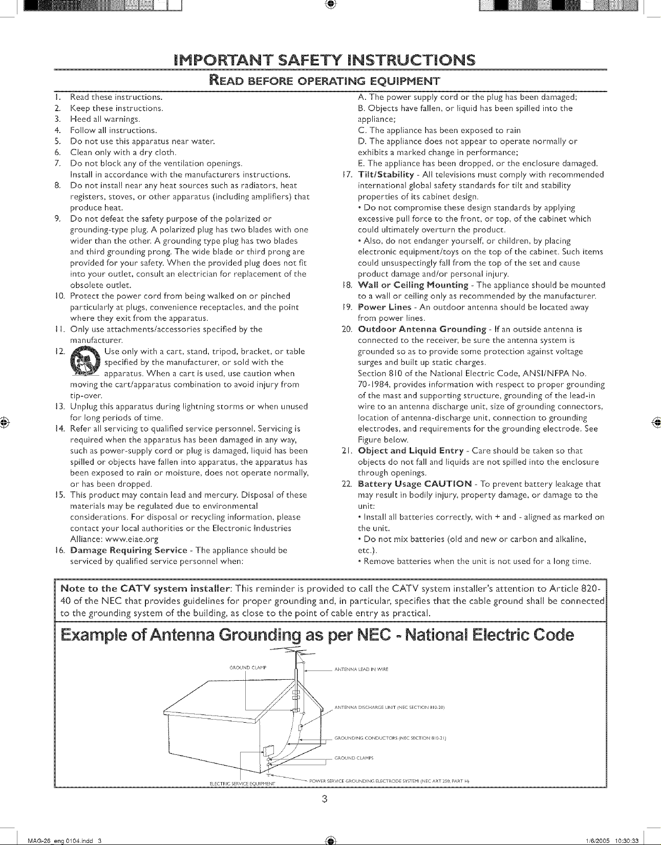
Note to the CATV system installer: This reminder is provided to call the CATV system installer's attention to Article 820-
40 of the NEC that provides guidelines for proper grounding and, in particular, specifies that the cable ground shall be connected
to the grounding system of the building, as close to the point of cable entry as practical.
Example of Antenna Grounding as per NEC - National Electric Code
• GROUND CLAHPS
ELEC:TRIC SERVICE EQU pHENT
MAG-26 engOl04indd 3 _ 1/6/2005 10:30:33 I
_-_ _ POWER SERVICE GROUNDING ELECTRODE SYSTEM (NEC ART 250 PART H_
3
introduction
Welcome/Registration of "four TV. ............................................ 2
IMPORTANT SAFETY INSTRUCTIONS ................................ 3
Table of Content ..............................................................................4
Getting Started
Before Installation .............................................................5
[nstafling LCD TV on The Wall ....................................................6
Basic TV and Remote Control Operations .............................7
Remote Contro[ ............................................................................... 8
Antenna Connection .......................................................................9
Connecting the Power cord .........................................................9
Basic Cable TV Connection ......................................................... 9
Cable Box Connections .................................................................IO
VCR, DVD Player, or other Devices
with RCA Connectors ....................................................................I I
DVD Player or other Video Devices
with Component Video Connectors ......................................... 12
Digital TV Receiver, or a Digital Satellite Receiver
with HD (High Definition) Output .............................................13
Digital Satellite Receiver with DVI connector. ......................... 14
PC (Monitor) Connection .............................................................. 15
AV Output ..........................................................................................16
Install Menu
LanguageSetd ngs..............................................................[7
Tuner Mode Control .......................................................................[8
Auto Program (Setting Up Channels) ........................................19
Channel Edit Control ...................................................................... 20
Factory Reset....................................................................................2[
CONTENT
General Information
Trouble Shooting Tips ...................................................36
Care And Cleaning .........................................................................37
Index ..................................................................................................38
Regulatory .........................................................................................39
Factory Service Locations ............................................................40
Factory Service Locations ............................................................ 41
Limited Warranty, ..........................................................................42
Here are a few of the special features of your new LCD TV,
Audio/Video In jacks: Use to quickly connect other
equipment to your LCD TV.
Automatic Channel Programming (Auto Program):
Quick and easy setup of available channels.
Closed Captioning: Allows the viewer to read TV program
dialog or voice conversations ason-screen text.
On-screen Menus: Helpful messages (in English, Spanish or
French) for setting TV controls.
Remote Control: Works your LCD TV features.
Sleep Timer: Turns offthe LCD TV within an amount of time
you specify (I 5-240 minutesfrom the current time).
AutoLock: Lets you block viewing of certain TV channels if you
do not want your children viewing inappropriate material,
Standard broadcast (VHF/UHF) or Cable TV channel
capability
Stereo capability: Includes a built-in amplifier and twin-speaker
system, allowing reception of TV programs broadcast in stereo.
Treb[e, Bass, and Balance: Enhance the LCD TV's sound.
_ Smart Picture and Smart Sound
Smart Sound Control ....................................................................22
_ Picture Nenu
_ Features Menu
Auto Loci<Access Code ................................................................26
Auto Loci<Program .........................................................................27
Auto Loci<- Movie Ratings............................................................ 28
Auto Loci<- TV Ratings ................................................................. 29
Using The Picture Format ............................................................. 30
Closed Captions .............................................................................31
PC Audio Controls ........................................................................ 33
Using PC PIP(Picture In Picture) Feature ...............................34
Setting Up The PC Mode ............................................................. 35
(Personal Computer Monitor) .....................................................35
Smart Picture Control ................................................... 22
TV PictureMenu Controls...........................................23
Sound Menu
TV Sound Menu Controls ............................................24
Auto Loci<.........................................................................25
PC Node
PC Picture Controls ...................................................... 32
Your new LCD TV and its packaging contain materials that can
be recycled and reused. SpedaIized companies can recycle your
product to increase the amount of reusable materials and
minimize the amounts that need to be properly disposed.
Your product also uses batteries that should not be thrown away
when depleted, but should be handed in and disposed of as small
chemical waste.
When you replace your existing equipment, please find out about
the local regulations regarding disposal of your old television,
batteries, and packing materials.
4
MAG-26 eng Ol04indd 4 _ 1/6/2005 10:30:341

BEFORE |NSTALLATION
ositioning the LCD TV.
°PlacetheLCDTVona solid,stablesurface,Besurethesu_aceis
strongenoughtohandletheweightoftheLCDTV.
,Do not place the LCD TVnear a radiator or other source of
heat.
°Tryto leave at least 6"of space around each side of the LCD
TV cabinet to allow for proper ventilation.
|DENTIFYING ALL CONNECTORS (BACKSIDE)
,Do not place the LCD TV where it can be exposed to rainor
excessive moisture.
@
°
r_J
_AVIN 1
Connects to the output jacks of your VCR or other
video equipment.
_AVIN 2
Connects to the output jacks of your VCR or other
video equipment.
Headphones jack
Connect to your headphones_
AV IN 3
Y, Pb, Pr Input jacks
Connects to the component video connectors of
your DVD player or other video equipments with
SD (Standard Definition) video formal
AV OUT
Connects to the input jacks of your video and audio
equipment.
Video output through AV OUT jacks isavailable only when
your LCD TV is displaying CVBS or RF signaJs_
VHF/UHF
Connect to your VHF/UHF antenna or cable
AC IN
Connects the supplied AC power cord.
DVI IN (HDCP)
Connect to your DVD player or other video equipment with
DVUH DCP output connectors_
PC IN
Connect to your PC with VGA type video output.
HD (High Definition) IN
Connect to the Digital Satellite Receiver or other video
equipments that supports YPbPr HD (High Definition) video
format.
MAG-26 eng0104.indd 5 _ 116/2005 10:30:35 I

NSTALLJNGLCD TV oN'THE WALL
eforeyoucaninstal!yourLCDTVonthe wall,you
mustfirst removethebaseusingthe stepsbelow:
Place the set facing down on a flat surface
with a protective sheet or cloth beneath
the TV.
Locate 2 screws beneath the base as
shown, remove the screws. Grasp the
base and pull it out.
Remove the 2 metal pins.
Attach the supplied base cover. Your
LCD TV is now ready for wall mounting.
When installing the LCDTV on the wall, please consult a professional technician for proper [nstallingo
The manufacture accepts no liability for installations not performed by professional technidan.
0
0
26"
32"
MAG-26 eng0104.indd 6 _ 1/6/2005 10:30:36 I
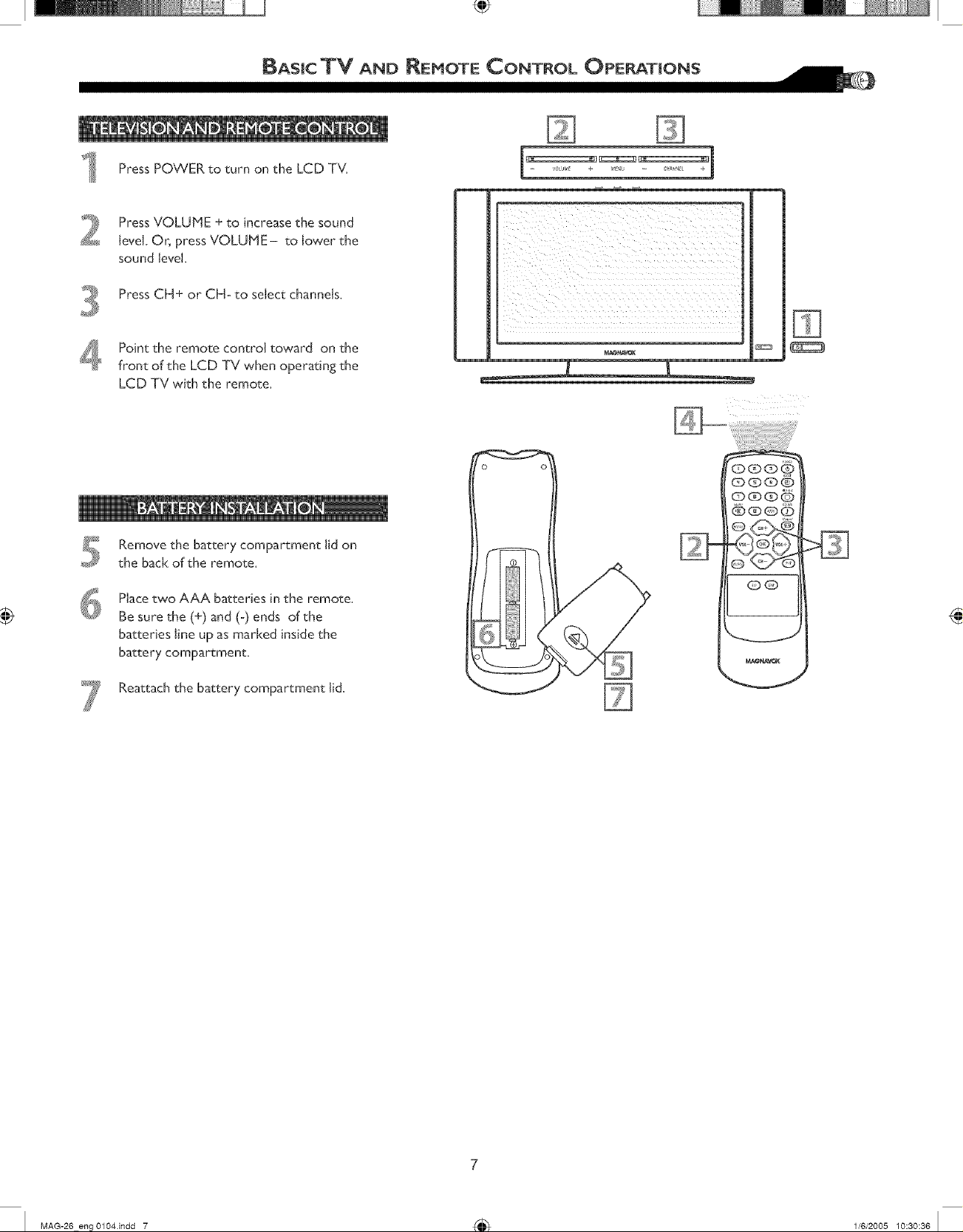
Press POWER to turn on the LCD TV.
Press VOLUME + to increase the sound
level. Or, press VOLUME- to lower the
sound level.
Press CH+ or CH° to select channels.
Point the remote control toward on the
front of the LCD TV when operating the
LCD TV with the remote,
Remove the battery compartment lid on
the back of the remote=
Place two AAA batteries in the remote,
Be sure the (+) and (-) ends of the
batteries line up as marked inside the
battery compartment.
QOQQ
QQ
Reattach the battery compartment lid.
MAG-26 eng Ol04indd 7 _ 1/6/2005 10:30:36 I
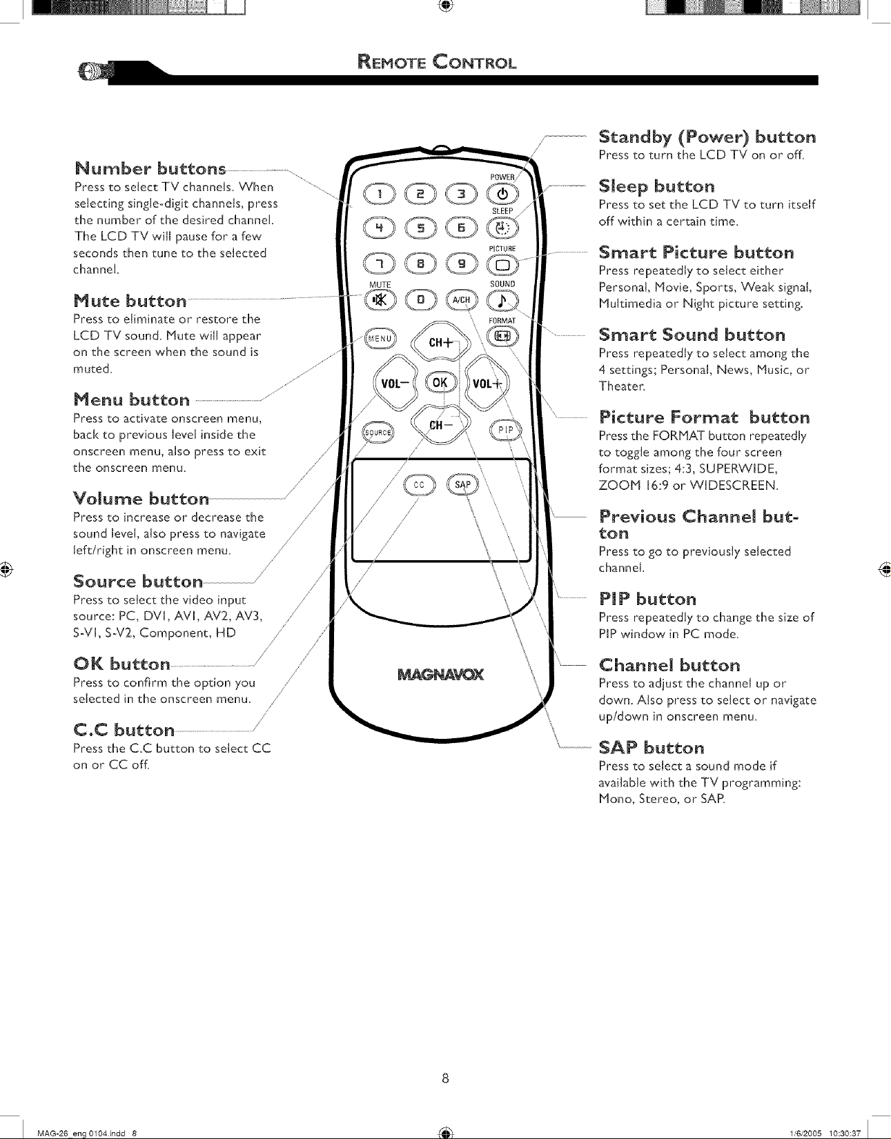
Number buttons ..........................
Press to select TV channels. When
selecting single-digit channels, press
the number of the desired channel.
The LCD TV will pause for a few
seconds then tune to the selected
channel.
@@@@
MUTE SOUND
Mute button
Press to eliminate or restore the
LCD TV sound. Mute will appear
on the screen when the sound is
muted.
Menu button .......................................................................
Press to activate onscreen menu,
back to previous level inside the
onscreen menu, also press to exit
the onscreen menu.
//
Volume button /
Press to increase or decrease the
sound level, also press to navigate
left/right in onscreen menu.
/
/ \
/
/
Source button
Press to select the video input
source: PC, DVI, AVI, AV2, AV3,
S-VL S°V2, Component, HD .....
OK button ......................................
Press to confirm the option you ,
selected in the onscreen menu.
/'
/
//
//
/
/
/
//
C.C button
Press the C.C button to select CC
on or CC off.
PICTURE
FORMAT
\
\ \
POWER/'
SLEEP _/
Standby (Power) button
Press to turn the LCD TV on or off.
Sleep button
Press to set the LCD TV to turn itself
off within a certak_ time.
Smart Picture button
Press repeatedly to select either
Personal, Movie, Sports, Weal< signal,
Plultimedia or Night picture setting.
Smart Sound button
Press repeatedly to select among the
4 settings; Personal, News, Music, or
Theater.
Picture Format button
Press the FOP, HAT button repeatedly
to toggle among the four screen
format sizes; 4:3, SUPERWIDE,
ZOOP1 16:9 or WIDESCREEN.
Previous Channel but°
ton
Press to go to previously selected
channel.
PI P button
Press repeatedly to change the size of
PIP window in PC mode.
Channel button
Press to adjust the channel up or
down. AIso press to select or navigate
up/down in onscreen menu.
SAP button
Press to select a sound mode if
available with the TV programming:
Hone, Stereo, or SAP.
MAG-20 eng Ol04indd 8 _ 1/6/2005 10:30:37 I

ANTENNA CONNECTION
A ombination antenna receivesnormal
broadcast channels (VHF 2-13 and UHF
14-69). "Yourconnection is easybecause there is
only one 75 L_antenna jack on the back of your TV,
and that's where the antenna goes.
Ifyour antenna has a round cable
(75 _) on the end, then you're ready to
connect it to the LCD TV. Ifyour
antenna has flat, twin°lead wire (300_),
you first need to attach the antenna wires
to the screws on a 300-75L_ adapter(not
supplied).
Connect the antenna (or adapter) to the
TV jack (marked 75 L_)on the rear of the
LCD TV. If the end of the antenna wire is
threaded, screw it down finger tight.
Outdoor or indoor Al_tenna
(Combination VHF/UHF)
..................................................................
Select weak signal mode via the smart
picture settings in case your antenna
connection is showing a lot of noise or
strange patterns.
BASIC CABLE TV CONNECTION
Twindeadwire
to 300-75_ adpter
or
with 75_
cable
our Cable TV signalinto your home may
be a single, 73 L_cable. If so,this
connection is very simple. Follow the step
below to connect your Cable TV signal to
your new LCD TV,
Connect the cable TV signal to the TV
jack (marked 75 _) on the rear of the
LCD TV. Screw it down finger tighL
Complete other connections prlor to
connecting the power cord.
Connect the power cord to the AC IN
connector of the LCD TV,
Connect the other plug of the power
cord to a wall outlet,
Rear Jackpanel of Television
CONNECTING THE POWER CORD
The Cable TV singal
from Cable Company
75Q coaxial cable
0
Wall outlet
ACIN
9
MAG-26 eng0104.indd 9 _ 1/6/2005 10:30:37 I

f you have a Cable Box, follow either set of
these steps to complete your connections.
Disconnect aJJ power sources before
making any connections.
Cable Box w_tb RF _n/Out jacks
This connection will not supply Stereo sound to
the LCD TV.
Connect the Cable TV signal to the IN jack
(or RF IN or CABLE IN) on the Cable Box.
Connect an RF coaxial cable (not supplied)
to the OUT jack (or TO TV or RF OUT) of
the Cable Box.
Connect the other end of the coaxial cable
to the TV jack (marked 75 O) on the rear
of the LCD TV.
TO
TV
Set the Channel (or Output channel) switch
of the CaNe Box to 3 or 4. Set the TV to
the same channel. When watching TV
programming, change channels at the Cable
Box, not the LCD TV.
Cable Box with AV (Audio/Video) Out
Jacks
This connection will supply Stereo sound to the
LCD TV.
Connect the Cable TV signal to the
IN jack (or RF IN or CABLE IN) on the
Cable Box.
Using an RCA-type Video and Audio cable
(marked with yellow, red, and white),
connect the Cable Box's Video and Audio
Out iacks to the TV's Video and Audio In
jacks.
Note:
I. If your" CaNe Box is equipped with a
S-Video Out Jack, use the S-Video
connection for a better picture detail
and clarity. Use the S-Video cable to
connect the Cable Box's S-Video Out
jacks to the TV's S_Video In iacks.
2. You can also use the Video and Audio
jacks in AV IN 2 and AV IN 3 located
on the rear of the TV to connect your
Cable Box.
3. Use the SOURCE button on the remote
control to select AV I (or AV2, AV3,
S-Videol, or S-Video2 if you use the
different iacks for this hookup) to watch
CaNe TV (your Cable Box must be
turned on).
10
C_L_
The Cable TV singat from Cabte Company
E
ou-fPU-f
cH
3 4
Cable Box
@@
AUDIO z
MAG-26 eng 0104.indd 10 _ 11612005 10:30:38 I

VCR, DVD PU ¥ER,OROTNERDEVICES
WITN RCA CONNECTORS
T e AV IN jacks on the rear of the LCD
TV enable quick connections of other
equipment. Connect a DVD playeryCR Video
Game, Camcorder, etc., to thesejacks. Toview the
material playing on the other equipment, set the
LCD TV to itsAV mode.
D_sconnect all power sources before
making any connections.
Using an RCA_type Video and Audio cable
(usually marked yellow, red, and white),
connect the VCR's Video and Audio Out
jacks to the TV's Video and Audio In iacks.
Use SOURCE button on the remote
control to select AV I (or AV2, AV3,
S_Videob or S_Video2 if you use the
different jacks for this hookup) to
watch VCR.
AUDIO z
Note:
I. if your VCR equipped with a
S-Video Out jaclq uses S-Video
connection for better picture detail
and clarity. Use the S-Video cable to
connect the VCR's S-Video Out
jacks to the TV's S_Video In iacks.
2. You can also use the Video and Audio
jacks in AV IN 2 and AV iN 3 located
on the rear of the TV to connect your
VCR or other Video Devices.
3. If your DVD Player is equipped with
Component (Y, Pb, Pr) Output Jacks,
please refer to "Connecting a DVD
Player or other Video Equipments with
Component Video Connectors" section
for use of Component Video
Connection for highest color and
picture resolution in video playback.
° The Audio iack of AV IN is shared
between Video (CVBS) and S_Video
signals. IfAudio and Video is connected
to Video (CVBS) input, you can still
hear sound if you select S-Video via
Source select, even there appears no
image on screen.
° Select weal< signal mode via the smart
picture settings in case your VCR is
showing a lot of noise or strange patterns
during play mode.
AV Hayer with A/V connectors
OQQ®
QO
11
MAG-26 eng 0104.indd 11 _ 11612005 10:30:39 I

DVD PLAYER OR OTHERMIDEO DEVICES
WITNC CONNECTORS
omponent:Video Input (Y,Pb,POprovide the
highest,possible color and picture resolution in
the playback of digit.alsignal source material, such
as with DVD player.
Disconnect all Dower sources before
making any connections.
Using a Component Video cable (not
supplied), connect the DVD player's Y, Pb,
Pr jacks to the Y, Pb, Pr jacks on the TV_
Use the AV IN 3 connections,
Note: The Component (Y, Pb, Pr) Video
Input in AV IN 3 connections can display
SD (4800 image only. If your DVD player
can output Progressh, e scanned or HD
(High Definition) image, please refer to
"Digital TV l_,eceiver, or a Digital Satellite
Receiver with HD (High Definition)
Output" in next section,
Using an AUDIO cable, connect the DVD
player's AUDIO OUT jacks to the TV's
AUDIO IN jacks in AV IN 3 connections,
Use Source button on the remote control
to select COMPONENT to watch DVD,
component video outputs
Accessory device equipped with
@@al
N
z
I
Note: I, The Y, Pb, Pr jacks do not
provide audio, so audio cables
must be connected to provide
sound,
(D(DQO
OO
12
MAG-26 eng 0104.indd 12 _ 11612005 10:30:39 I
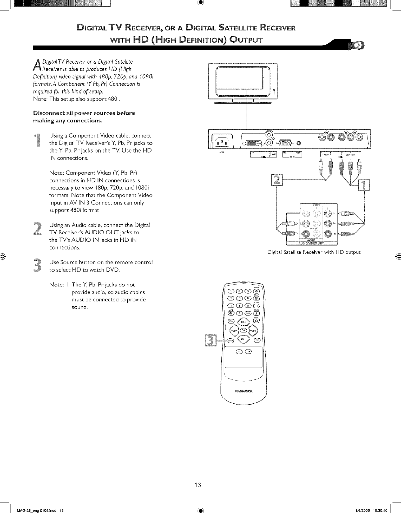
A igital TV Receiver or a Digital Satellite
Receiveris able to produces HD (High
De_nition) video signal with 480p, 720p, and 1080i
formats, A Component (Y Pb,PO Connection is
required for this kind o_setup,
Note: This setup also support 480L
Disconnect aJi power sources before
making any connections.
Using a Component Video cable, connect
the Digital TV Receiver's Y, Pb, Pr jacks to
the Y, Pb, Pr jacks on the TV=Use the HD
IN connections=
Note: Component Video (Y, Pb, Pr)
connections in HD IN connections is
necessary to view 480p, 720p, and 1080i
formats. Note that the Component Video
Input in AV IN 3 Connections can only
support 480i format,
Using an Audio cable, connect the Digital
TV Receiver's AUDIO OUT jacks to
the TV's AUDIO IN jacks in HD IN
connections=
Use Source button on the remote control
to select HD to watch DVD=
E
Digital Satellite Receiver with HD output
Note: I=The Y, Pb, Pr jacks do not
provide audio, so audio cables
must be connected to provide
sound=
CDOCD6
000(39
QG
v_
13
MAG-26 eng 0104.indd 13 _ 1/6/2005 10:30:40 I
 Loading...