

Magnavox 19MDTR20, 19MDTR17, 27MDTR20S, 27MDTR17S Service Manual
MANUAL 5891 Color TV with Built-In VCR/DVD Player Magnavox 27MDTR20S/17, 19MDTR20/17
Philips Consumer Electronics Company
A Division of Philips Electronics North America Corporation
Technical Service Data
Service Solutions Group
Technical Publications Dept.
P.O. Box 555, 401 E. Old Andrew Johnson Hwy.
Jefferson City,TN 37760
Sec. 1A: Main Section
( 27MDTR20S/17 )
Supplement 1
Sec. 1B: Main Section
( 19MDTR20/17 )
Specifications
Adjustment Procedures
Schematic Diagrams and CBA’s
Exploded Views
Cabinet & Electrical Parts Lists
MANUAL 5891
Sec. 2: Deck Mechanism Section
Color TV with Built-In VCR/DVD Player
Service Manual
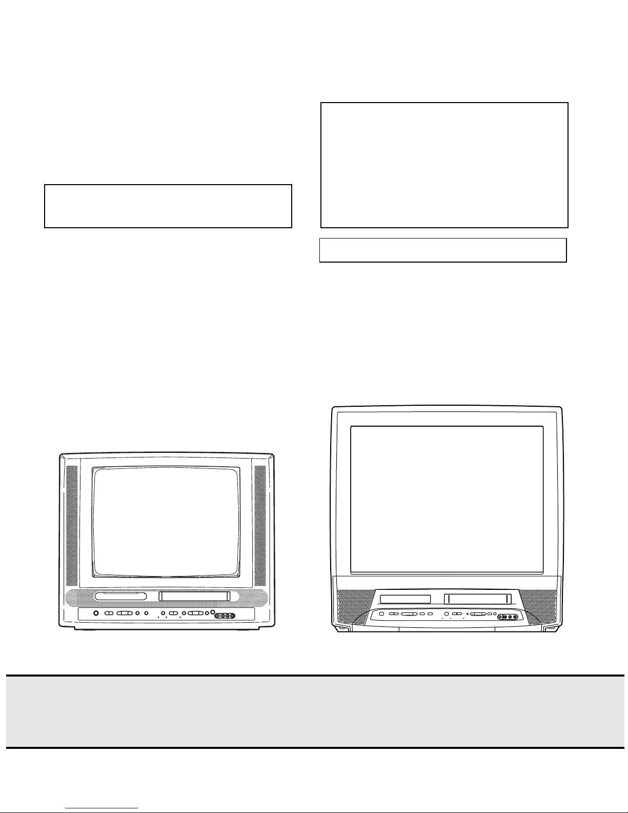
MAGNAVOX
Model: 19MDTR20/17
MAGNAVOX
Model: 27MDTR20S/17
Color TV with Built-In VCR/DVD Player
First Issue: 5/03
2003 Philips Consumer Electronics Company
Philips Consumer Electronics Company
A Division of Philips Electronics North America Corporation
Technical Service Data
Service Solutions Group
Technical Publications Dept.
P.O. Box 555, 401 E. Old Andrew Johnson Hwy.
Jefferson City,TN 37760
Supplement 1
Sec. 1B: Main Section
( 19MDTR20/17 )
Specifications
Adjustment Procedures
Schematic Diagrams and CBA’s
Exploded Views
Cabinet & Electrical Parts Lists
MANUAL 5891
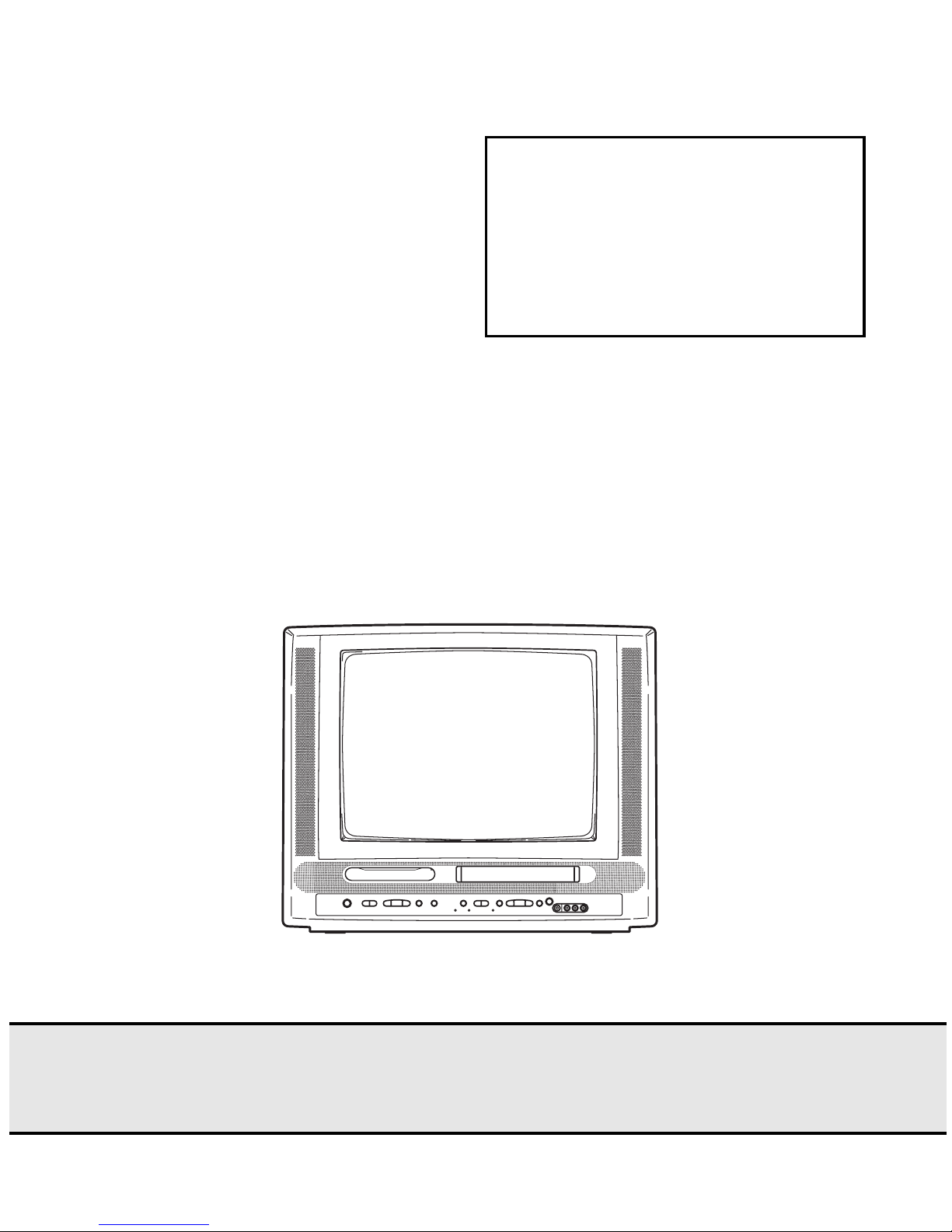
Color TV with Built-In VCR/DVD Player
Service Manual
MAGNAVOX
Model: 19MDTR20/17
Color TV with Built-In VCR/DVD Player
First Issue: 5/03
2003 Philips Consumer Electronics Company

IMPORTANT SAFETY NOTICE
Proper service and repair is important to the safe, reliable operation of all
Philips Consumer Electronics Company** Equipment. The service procedures
recommended by Philips and described in this service manual are effective
methods of performing service operations. Some of these service operations
require the use of tools specially designed for the purpose. The special tools
should be used when and as recommended.
It is important to note that this manual contains various CAUTIONS and
NOTICES which should be carefully read in order to minimize the risk of personal injury to service personnel. The possibility exists that improper service
methods may damage the equipment. It also is important to understand that
these CAUTIONS and NOTICES ARE NOT EXHAUSTIVE. Philips could not
possibly know, evaluate and advise the service trade of all conceivable ways
in which service might be done or of the possible hazardous consequences of
each way. Consequently, Philips has not undertaken any such broad evaluation. Accordingly, a servicer who uses a service procedure or tool which is
not recommended by Philips must first satisfy himself thoroughly that neither
his safety nor the safe operation of the equipment will be jeopardized by the
service method selected.
** Hereafter throughout this manual, Philips Consumer Electronics Company
will be referred to as Philips.
WARNING
Critical components having special safety characteristics are identified
with a # by the Ref. No. in the parts list and enclosed within a broken
line* (where several critical components are grouped in one area) along
with the safety symbol # on the schematics or exploded views.
Use of substitute replacement parts which do not have the same specified
safety characteristics may create shock, fire, or other hazards.
Under no circumstances should the original design be modified or altered
without written permission from Philips. Philips assumes no liability,
express or implied, arising out of any unauthorized modification of
design. Servicer assumes all liability.
* Broken Line
Manufactured under license from Dolby Laboratories. "Dolby"
and the double-D symbol are trademarks of Dolby Laboratories.

TABLE OF CONTENTS
Note:
One model, 19MDTR20/17, is covered by Supplement 1. This section only shows what differs between this model and
its base model covered by Section 1A and the Deck Mechanism Section.
[ Main Section ]
Page
SPECIFICATIONS . . . . . . . . . . . . . . . . . . . . . . . . . . . . . . . . . . . . . . . . . . . . . . . . . . . . . . . . . . . . . . . . . . . . . . . . . . . . 1-1-1
PREPARATION FOR SERVICING. . . . . . . . . . . . . . . . . . . . . . . . . . . . . . . . . . . . . . . . . . . . . . . . . . . . . . . . . . . . . . . . 1-2-1
CABINET DISASSEMBLY INSTRUCTIONS . . . . . . . . . . . . . . . . . . . . . . . . . . . . . . . . . . . . . . . . . . . . . . . . . . . . . . . . 1-3-1
ELECTRICAL ADJUSTMENT INSTRUCTIONS . . . . . . . . . . . . . . . . . . . . . . . . . . . . . . . . . . . . . . . . . . . . . . . . . . . . . 1-4-1
Adjustment Points and Test Points . . . . . . . . . . . . . . . . . . . . . . . . . . . . . . . . . . . . . . . . . . . . . . . . . . . . . . . . . . . . . 1-4-7
BLOCK DIAGRAMS . . . . . . . . . . . . . . . . . . . . . . . . . . . . . . . . . . . . . . . . . . . . . . . . . . . . . . . . . . . . . . . . . . . . . . . . . . 1-5-1
Servo/System Control Block Diagram . . . . . . . . . . . . . . . . . . . . . . . . . . . . . . . . . . . . . . . . . . . . . . . . . . . . . . . . . . 1-5-1
Video Block Diagram . . . . . . . . . . . . . . . . . . . . . . . . . . . . . . . . . . . . . . . . . . . . . . . . . . . . . . . . . . . . . . . . . . . . . . . 1-5-3
Audio Block Diagram . . . . . . . . . . . . . . . . . . . . . . . . . . . . . . . . . . . . . . . . . . . . . . . . . . . . . . . . . . . . . . . . . . . . . . . 1-5-5
Hi-Fi Audio Block Diagram . . . . . . . . . . . . . . . . . . . . . . . . . . . . . . . . . . . . . . . . . . . . . . . . . . . . . . . . . . . . . . . . . . . 1-5-7
Chroma Block Diagram . . . . . . . . . . . . . . . . . . . . . . . . . . . . . . . . . . . . . . . . . . . . . . . . . . . . . . . . . . . . . . . . . . . . . 1-5-9
CRT/H.V. Block Diagram . . . . . . . . . . . . . . . . . . . . . . . . . . . . . . . . . . . . . . . . . . . . . . . . . . . . . . . . . . . . . . . . . . . . 1-5-11
Power Supply Block Diagram. . . . . . . . . . . . . . . . . . . . . . . . . . . . . . . . . . . . . . . . . . . . . . . . . . . . . . . . . . . . . . . . . 1-5-13
DVD System Control/Servo Block Diagram . . . . . . . . . . . . . . . . . . . . . . . . . . . . . . . . . . . . . . . . . . . . . . . . . . . . . . 1-5-15
Digital Signal Process Block Diagram . . . . . . . . . . . . . . . . . . . . . . . . . . . . . . . . . . . . . . . . . . . . . . . . . . . . . . . . . . 1-5-17
DVD Audio Block Diagram . . . . . . . . . . . . . . . . . . . . . . . . . . . . . . . . . . . . . . . . . . . . . . . . . . . . . . . . . . . . . . . . . . . 1-5-19
SCHEMATIC DIAGRAMS / CBA’S AND TEST POINTS . . . . . . . . . . . . . . . . . . . . . . . . . . . . . . . . . . . . . . . . . . . . . . . 1-6-1
Main 1/5 Schematic Diagram Parts Location Guide. . . . . . . . . . . . . . . . . . . . . . . . . . . . . . . . . . . . . . . . . . . . . . . . 1-6-2
Main 1/5 Schematic Diagram <TV/VCR SECTION> . . . . . . . . . . . . . . . . . . . . . . . . . . . . . . . . . . . . . . . . . . . . . . . 1-6-3
Main 2/5 Schematic Diagram <TV/VCR SECTION> . . . . . . . . . . . . . . . . . . . . . . . . . . . . . . . . . . . . . . . . . . . . . . . 1-6-5
Main 2/5 Schematic Diagram Parts Location Guide. . . . . . . . . . . . . . . . . . . . . . . . . . . . . . . . . . . . . . . . . . . . . . . . 1-6-7
Main 3/5 Schematic Diagram Parts Location Guide. . . . . . . . . . . . . . . . . . . . . . . . . . . . . . . . . . . . . . . . . . . . . . . . 1-6-8
Main 3/5 Schematic Diagram <TV/VCR SECTION> . . . . . . . . . . . . . . . . . . . . . . . . . . . . . . . . . . . . . . . . . . . . . . . 1-6-9
Main 4/5 Schematic Diagram <TV/VCR SECTION> . . . . . . . . . . . . . . . . . . . . . . . . . . . . . . . . . . . . . . . . . . . . . . . 1-6-11
Main 4/5 Schematic Diagram Parts Location Guide. . . . . . . . . . . . . . . . . . . . . . . . . . . . . . . . . . . . . . . . . . . . . . . . 1-6-13
Main 5/5 Schematic Diagram Parts Location Guide. . . . . . . . . . . . . . . . . . . . . . . . . . . . . . . . . . . . . . . . . . . . . . . . 1-6-14
Main 5/5 Schematic Diagram <TV/VCR SECTION> . . . . . . . . . . . . . . . . . . . . . . . . . . . . . . . . . . . . . . . . . . . . . . . 1-6-15
Main CBA Parts Location Guide. . . . . . . . . . . . . . . . . . . . . . . . . . . . . . . . . . . . . . . . . . . . . . . . . . . . . . . . . . . . . . . 1-6-17
Main CBA Top View <TV/VCR SECTION> . . . . . . . . . . . . . . . . . . . . . . . . . . . . . . . . . . . . . . . . . . . . . . . . . . . . . . 1-6-19
Main CBA Bottom View <TV/VCR SECTION>. . . . . . . . . . . . . . . . . . . . . . . . . . . . . . . . . . . . . . . . . . . . . . . . . . . . 1-6-21
Power Supply/AV CBA Top View <TV/VCR SECTION>. . . . . . . . . . . . . . . . . . . . . . . . . . . . . . . . . . . . . . . . . . . . . 1-6-23
Power Supply/AV CBA Bottom View <TV/VCR SECTION>. . . . . . . . . . . . . . . . . . . . . . . . . . . . . . . . . . . . . . . . . . 1-6-25
Power Supply/AV CBA Parts Location Guide. . . . . . . . . . . . . . . . . . . . . . . . . . . . . . . . . . . . . . . . . . . . . . . . . . . . . 1-6-27
Power Supply/AV 1/2 Schematic Diagram Parts Location Guide . . . . . . . . . . . . . . . . . . . . . . . . . . . . . . . . . . . . . . 1-6-29
Power Supply/AV 1/2 Schematic Diagram <TV/VCR SECTION> . . . . . . . . . . . . . . . . . . . . . . . . . . . . . . . . . . . . . 1-6-31
Power Supply/AV 2/2 Schematic Diagram <TV/VCR SECTION> . . . . . . . . . . . . . . . . . . . . . . . . . . . . . . . . . . . . . 1-6-33
Power Supply/AV 2/2 Schematic Diagram Parts Location Guide . . . . . . . . . . . . . . . . . . . . . . . . . . . . . . . . . . . . . . 1-6-35
H.V.Schematic Diagram Parts Location Guide. . . . . . . . . . . . . . . . . . . . . . . . . . . . . . . . . . . . . . . . . . . . . . . . . . . . 1-6-36
H.V. Schematic Diagram <TV/VCR SECTION> . . . . . . . . . . . . . . . . . . . . . . . . . . . . . . . . . . . . . . . . . . . . . . . . . . . 1-6-37
Junction A/B CBA Top/Bottom View. . . . . . . . . . . . . . . . . . . . . . . . . . . . . . . . . . . . . . . . . . . . . . . . . . . . . . . . . . . . 1-6-39
H.V. CBA Parts Location Guide . . . . . . . . . . . . . . . . . . . . . . . . . . . . . . . . . . . . . . . . . . . . . . . . . . . . . . . . . . . . . . . 1-6-40
H.V. CBA Top View <TV/VCR SECTION> . . . . . . . . . . . . . . . . . . . . . . . . . . . . . . . . . . . . . . . . . . . . . . . . . . . . . . . 1-6-41
H.V. CBA Bottom View <TV/VCR SECTION> . . . . . . . . . . . . . . . . . . . . . . . . . . . . . . . . . . . . . . . . . . . . . . . . . . . . 1-6-43
CRT Schematic Diagram <TV/VCR SECTION> . . . . . . . . . . . . . . . . . . . . . . . . . . . . . . . . . . . . . . . . . . . . . . . . . . 1-6-45
Function Schematic Diagram <TV/VCR SECTION> . . . . . . . . . . . . . . . . . . . . . . . . . . . . . . . . . . . . . . . . . . . . . . . 1-6-45
CRT CBA Top/Bottom View <TV/VCR SECTION> . . . . . . . . . . . . . . . . . . . . . . . . . . . . . . . . . . . . . . . . . . . . . . . . 1-6-47
Function CBA Top/Bottom View <TV/VCR SECTION> . . . . . . . . . . . . . . . . . . . . . . . . . . . . . . . . . . . . . . . . . . . . . 1-6-49
DVD Main 1/3 Schematic Diagram <DVD SECTION> . . . . . . . . . . . . . . . . . . . . . . . . . . . . . . . . . . . . . . . . . . . . . . 1-6-51
DVD Main 2/3 Schematic Diagram <DVD SECTION> . . . . . . . . . . . . . . . . . . . . . . . . . . . . . . . . . . . . . . . . . . . . . . 1-6-53
IC101 Voltage Chart. . . . . . . . . . . . . . . . . . . . . . . . . . . . . . . . . . . . . . . . . . . . . . . . . . . . . . . . . . . . . . . . . . . . . . . . 1-6-55
DVD Main 3/3 Schematic Diagram <DVD SECTION> . . . . . . . . . . . . . . . . . . . . . . . . . . . . . . . . . . . . . . . . . . . . . . 1-6-57
WIRING DIAGRAM <TV/VCR SECTION> . . . . . . . . . . . . . . . . . . . . . . . . . . . . . . . . . . . . . . . . . . . . . . . . . . . . . . . . . 1-7-1
WIRING DIAGRAM <DVD SECTION> . . . . . . . . . . . . . . . . . . . . . . . . . . . . . . . . . . . . . . . . . . . . . . . . . . . . . . . . . . . . 1-7-3
IC PIN FUNCTION DESCRIPTIONS . . . . . . . . . . . . . . . . . . . . . . . . . . . . . . . . . . . . . . . . . . . . . . . . . . . . . . . . . . . . . 1-8-1
LEAD IDENTIFICATIONS . . . . . . . . . . . . . . . . . . . . . . . . . . . . . . . . . . . . . . . . . . . . . . . . . . . . . . . . . . . . . . . . . . . . . . 1-9-1
ELECTRICAL PARTS LIST . . . . . . . . . . . . . . . . . . . . . . . . . . . . . . . . . . . . . . . . . . . . . . . . . . . . . . . . . . . . . . . . . . . . . 1-10-1
EXPLODED VIEWS . . . . . . . . . . . . . . . . . . . . . . . . . . . . . . . . . . . . . . . . . . . . . . . . . . . . . . . . . . . . . . . . . . . . . . . . . . 1-11-1
MECHANICAL PARTS LIST . . . . . . . . . . . . . . . . . . . . . . . . . . . . . . . . . . . . . . . . . . . . . . . . . . . . . . . . . . . . . . . . . . . . 1-12-1
SPECIFICATIONS
*ˆMode---------SP mode unless otherwise specified
*Test input terminal
<Except Tuner>-------------Video input (1Vp-p)
Audio input (-10dB)
<Tuner>-----------------------Ant. input (80dBµV) Video: 87.5%
Audio: 25kHz dev (1kHz Sin)
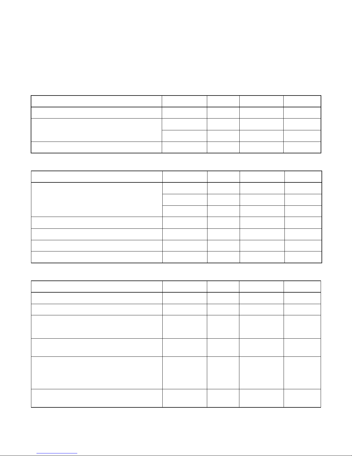
<DEFLECTION>
Description Condition Unit Nominal Limit
1. Over Scan — % 90 —
2. Linearity
3. High Voltage — kV 25 —
Horizontal % — 15
Vertical % — 10
<VIDEO & CHROMA>
Description Condition Unit Nominal Limit
Center m/m — 0.4
1. Misconvergence
2. Tint Control Range — deg ±30 —
3. Contrast Control Range — dB 6 2
4. Brightness (100% White Full Field) Contrast: Max ft-L 35 24
5. Color Temperature — K 9200 —
Corner m/m — 2.5
Side m/m — 1.5
<DVD>
Description Condition Unit Nominal Limit
1. Horizontal Resolution (TDV-540 TIT.2 CHP.16) — Line 330 320
2. Video S/N at CN3400 (TDV-540 TIT.2 CHP.6) — dB 60 55
3. S/N Chroma at CN3400 AM — dB 58 53
(TDV-540 TIT.2 CHP.17) PM — dB 58 53
4. Audio Distortion (LPCM 48 kHz, W/LPF)
(PTD 1-NOR TIT.1 CHP.1)
5. Audio freq. response (LPCM 48kHz)
(PTD 1-NOR TIT.1 CHP.5 -- 10)
6. Audio S/N (LPCM 48KHz,W/LPF,A-WTD)
(PTD 1-NOR TIT.1 CHP.1 -- 2)
L
R
L, 20 Hz
R, 20 Hz
L, 20 kHz
R, 20 kHz
L
R
1-1-1 TD851SP
%
dB 0 +4/-5
dB 85 75
0.03
0.03
0.07
0.07
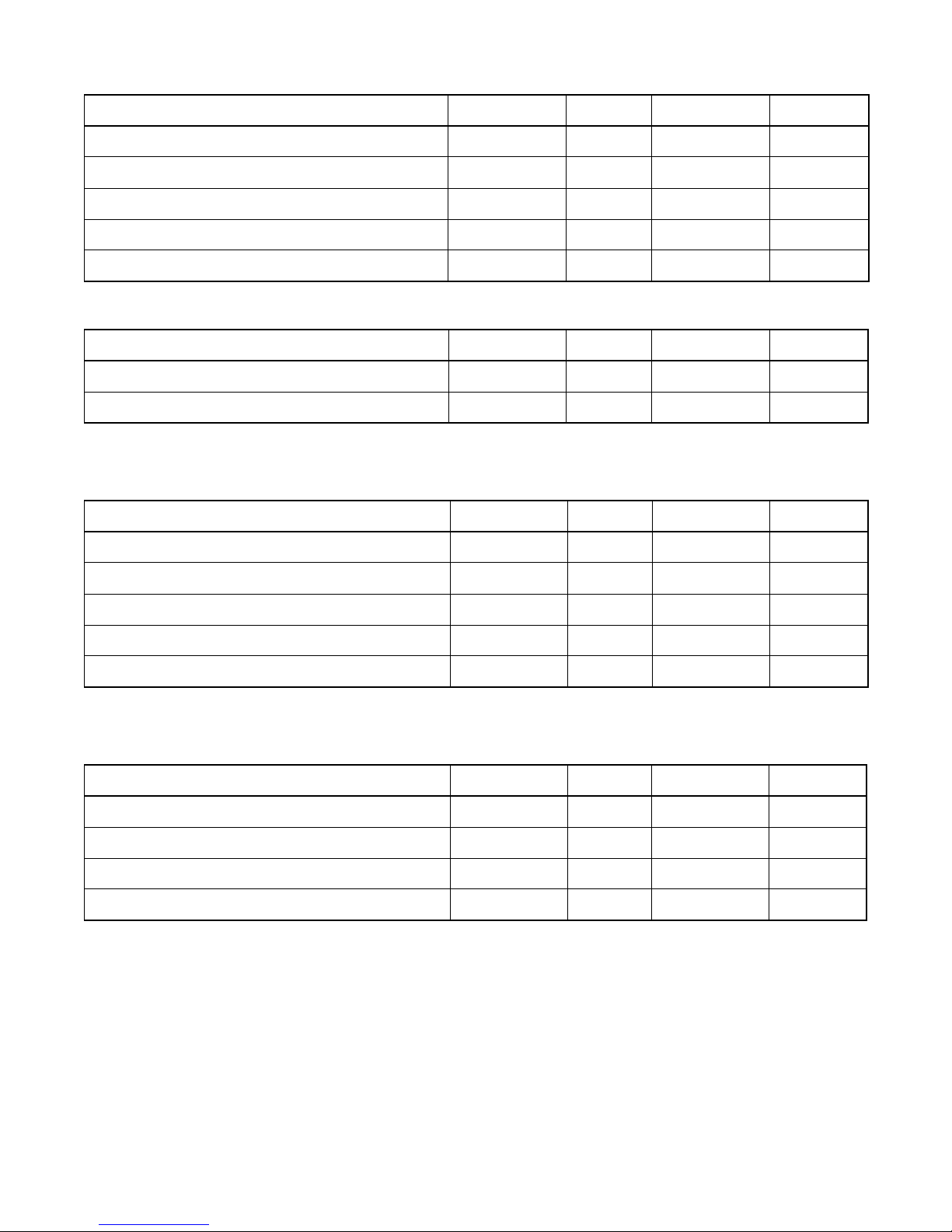
<VCR>
Description Condition Unit Nominal Limit
1. Horizontal Resolution (R/P, SP) Line 230 200
2. Jitter (Low) (R/P, SP) µS0.1 0.2
3. S/N Chroma AM(SP) (R/P, SP) dB 38 33
PM(SP) (R/P, SP) dB 38 33
4. Wow & Flutter (JIS, UNWTD) (R/P, SP) % 0.25 0.5
<TUNER>
Description Condition Unit Nominal Limit
1. Video S/N (80dBµV, TV4ch) — dB 45 40
2. Audio S/N (W/LPF) — dB 45 40
<NORMAL AUDIO>
All items are measured across 8Ω resistor at speaker output terminal.
Description Condition Unit Nominal Limit
1. Audio Output Power (R/P, SP) W 1.0 0.8
2. Audio S/N (W/LPF) (R/P, SP) dB 40 36
3. Audio distortion (W/LPF,-10dB 1kHz IN) (R/P, SP) % 3.0 5.0
4. Audio Freq. Response (-10dB 1kHz IN) 200 Hz (R/P, SP) dB -2.0 -2.0±5.0
8 kHz (R/P, SP) dB 0 0±6.0
<Hi-Fi AUDIO>
All items are measured at TP1701 and TP1702.
Description Condition Unit Nominal Limit
1. Output Level (-10dB 1kHz IN) (R/P, SP) dB -8.0 -8±4
2. Audio Distortion (-10dB 1kHz IN) (R/P, SP) % 0.5 1.0
3. Freq. Response (-15dB 1kHz IN) 20 Hz (R/P, SP) dB 0 ±4
20 kHz (R/P, SP) dB 0 ±4
Note: Nominal specifications represent the design specifications. All units should be able to approximate these.
Some will exceed and some may drop slightly below these specifications. Limit specifications represent the absolute worst condition that still might be considered acceptable. In no case should a unit fail to meet limit specifications.
1-1-2 TD851SP
PREPARATION FOR SERVICING
How to Enter the Service Mode
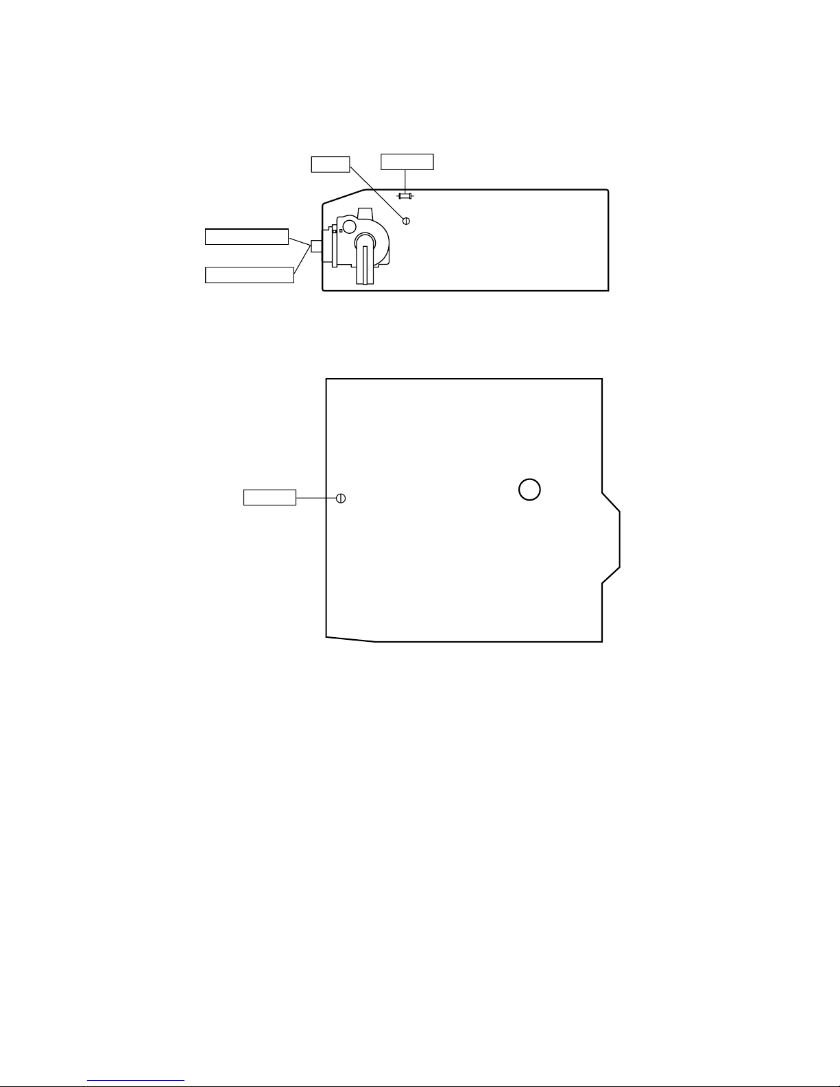
Caution: 1
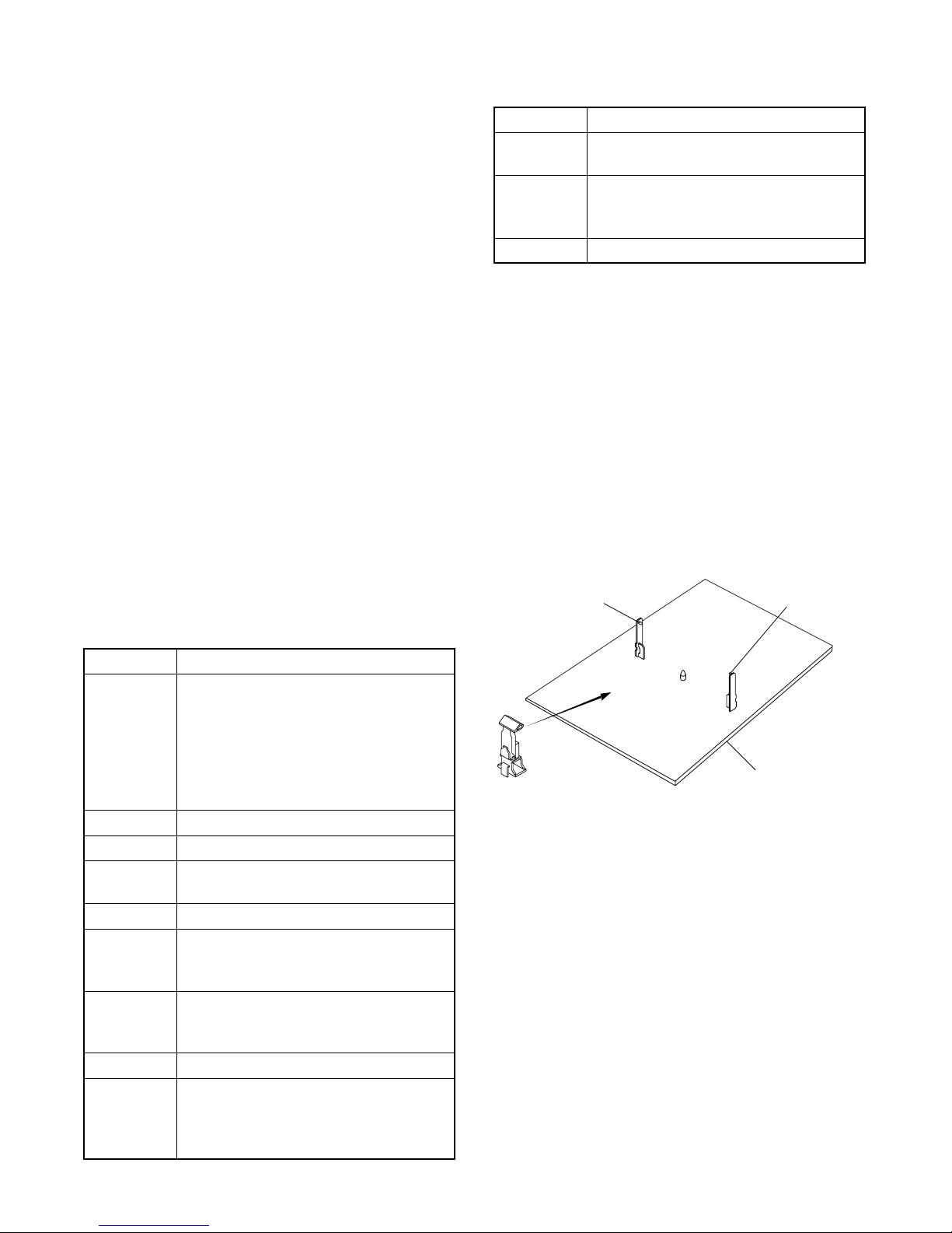
1. Optical sensors system are used for Tape Start and
End Sensor on this equipment. Read this page
carefully and prepare as described on this page
before starting to service; otherwise, the unit may
operate unexpectedly.
Preparing: 1
1. Cover Q202 (START SENSOR) and Q201 (END
SENSOR) with Insulation Tape or enter the service
mode to activate Sensor Inhibition automatically.
Note: Avoid playing, rewinding or fast forwarding the
tape to its beginning or end, because both Tape End
Sensors are not active.
How to Enter the Service Mode
1. Turn power on.
2. Use service remote control unit and press DISC
MENU key. (See page 1-4-1)
3. When entering the service mode, one of the number (1, 2 or 4) will display at corners of the screen.
4. During the service mode, electrical adjustment
mode can be selected by remote control key. (Service remote control unit).
Details are as follows.
Key Adjustment Mode
8
9
VOL p Cut-off Adjustment 1-4-3.
Caution: 2
1. The deck mechanism assembly is mounted on the
Main CBA directly, and SW1211 (REC-SAFETY
SW) is mounted on the Main CBA. When deck
mechanism assembly is removed from the Main
CBA due to servicing, this switch can not be operated automatically.
H. Shift adjustment mode: See adjustment instructions page 1-4-3.
V.size/V. shift adjustment: See adjustment instructions pages 1-4-2 and
1-4-3.
Preparing: 2
1. To eject the tape, press the STOP/EJECT button
on the unit (or Remote Control).
2. When you want to record during the Service mode,
press the Rec button while depressing SW1211
(REC-SAFETY SW) on the Main CBA.
Q201
(END SENSOR)
Q202
(START SENSOR)
Key Adjustment Mode
Picture adjustment mode: Press the
MENU button to change from BRT
(Bright), *CNT (Contrast),
MENU
0 No need to use.
1 No need to use.
2
3 No need to use.
4
5
6 No need to use.
7
*COL(Color), *TNT(Tint) and *V-T.
Press CH UP/DOWN key to adjust Initial Value. *Marked items are not necessary to adjust normally.
H adjustment mode: See adjustment
instructions page 1-4-2.
Auto record mode: Perform recording
(15 Sec.)-->Stop-->Rewind (Zero
return) automatically.
Head switching point adjustment
mode: See adjustment instructions
page 1-4-5.
Purity check mode: Shows Red,
Green, Blue or White cyclically on the
screen each time the “7” key is
pressed.
SW1211
(REC-SAFETY SW)
MAIN CBA
1-2-1 TD857PFS
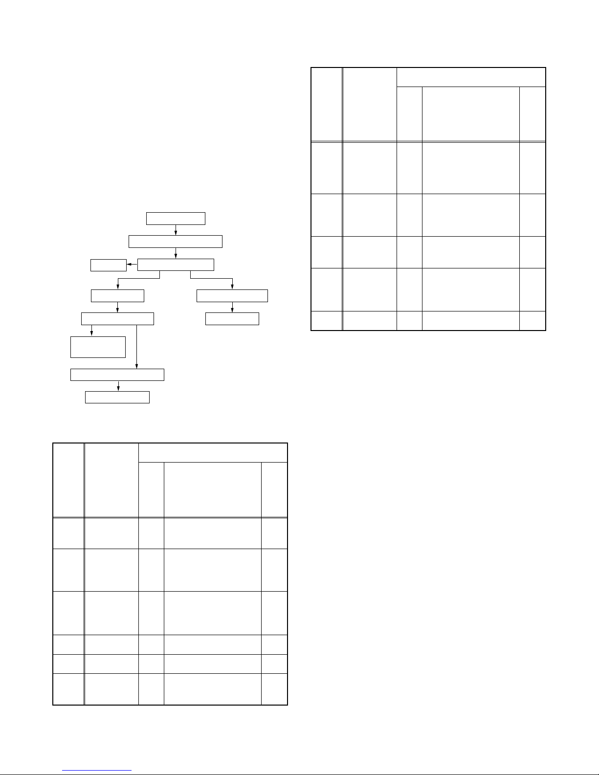
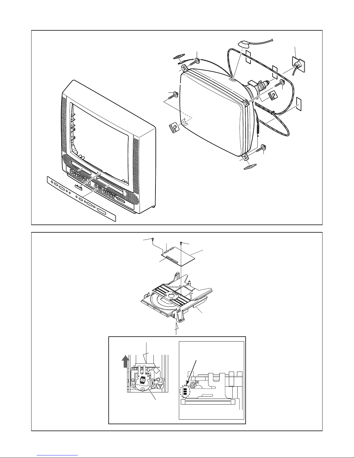
CABINET DISASSEMBLY INSTRUCTIONS
1. Disassembly Flowchart
This flowchart indicates the disassembly steps for the
cabinet parts, and the CBA in order to gain access to
item(s) to be serviced. When reassembling, follow the
steps in reverse order. Bend, route and dress the
cables as they were.
Caution !
When removing the CRT, be sure to discharge the
Anode Lead of the CRT with the CRT Ground Wire
before removing the Anode Cap.
[1] Rear Cabinet
[2] H.V. CBA (with Holder)
[4] CRT
[5] Shield Box
[6] DVD Mechanism
[7] DVD Main
CBA Unit
[3] Tray Chassis Unit
[10] Deck Assembly
[11] Main CBA
REMOVAL
ID/
LOC.
No.
PAR T
REMOVE/
*UNHOOK/UNLOCK/
Fig.
No.
RELEASE/UNPLUG/
DESOLDER
[7]
[8]
[9]
[10]
DVD Main
CBA Unit
Power
Supply/AV
CBA
Function
CBA
Deck
Assembly
2(S-7), CN201,
5
CN301
4(S-8), CN2803,
3, 6
CN2804
3 3(S-9) -
7(S-10), 2(S-11),
3, 6
CL1201, CL1401,
CL1402, CL1403
[11] Main CBA 3 3(S-12) -
↓
(1)
↓
(2)
↓
(3)
↓
(4)
Note
2-1
2-2
2-3
3
-
4
↓
(5)
[8] Power Supply/AV CBA
[9] Function CBA
2. Disassembly Method
REMOVAL
ID/
LOC.
PART
No.
Rear
[1]
Cabinet
H.V. CBA
[2]
(With
Holder)
Tr ay
[3]
Chassis
Unit
[4] CRT 4 4(S-4) -
REMOVE/
*UNHOOK/UNLOCK/
Fig.
No.
RELEASE/UNPLUG/
DESOLDER
1, 2 6(S-1), 1(S-2), 1(S-3) -
Anode Cap, CN501,
3, 4,
CRT CBA, CN571,
6
CN1301, CN2602
CN1802, CN2801,
3, 6
CN2601
Note
1
-
(1): Order of steps in Procedure. When reassembling,
follow the steps in reverse order.These numbers
are also used as the Identification (location) No. of
parts in Figures.
(2): Parts to be removed or installed.
(3): Fig. No. showing Procedure of Part Location.
(4): Identification of part to be removed, unhooked,
unlocked, released, unplugged, unclamped, or
desoldered.
S=Screw, P=Spring, L=Locking Tab, CN=Connec-
tor, *=Unhook, Unlock, Release, Unplug, or
Desolder
2(S-2) = two Screw (S-2)
(5): Refer to the following "Reference Notes in the
Table."
[5] Shield Box 3 5(S-5) -
DVD
[6]
Mechanism
CN2401, CN2402,
3, 6
3(S-6)
-
1-3-1 TD857DC

Reference Notes in the Table
Caution !
When removing the CRT, be sure to discharge the
Anode Lead of the CRT with the CRT Ground Wire
before removing the Anode Cap.
Reference Notes in the Table
CAUTION 1: Discharge the Anode Lead of the CRT
with the CRT Ground Wire before removing the Anode
Cap.
1. Disconnect the following: Anode Cap, CN501, CRT
CBA, CN571, CN2602, and CN1301.
Then remove H.V. CBA (with Holder).
CAUTION 2: Electrostatic breakdown of the laser
diode in the optical system block may occur as a
potential difference caused by electrostatic charge
accumulated on cloth, human body etc., during
unpacking or repair work.
To avoid damage of pickup follow these procedures.
2-1. Slide out the pickup unit as shown in Fig. 5.
2-2. Short the three short lands of FPC cable with sol-
der before removing the FFC cable (CN201) from
it. If you disconnect the FFC cable (CN201), the
laser diode of pickup will be destroyed. (Fig. 5)
2-3. Disconnect connector (CN301). Remove two
screws (S-7) and lift the DVD Main CBA Unit.
(Fig. 5)
CAUTION 3: When reassembling, confirm the FFC
cable (CN201) is connected completely. Then remove
the solder from the three short lands of FPC cable.
(Fig. 5)
4. Remove screws 7(S-10) and 2(S-11). Then, desolder connectors (CL1201, C1401, CL1402, CL1403)
and lift up the Deck Assembly.
1-3-2 TD857DC
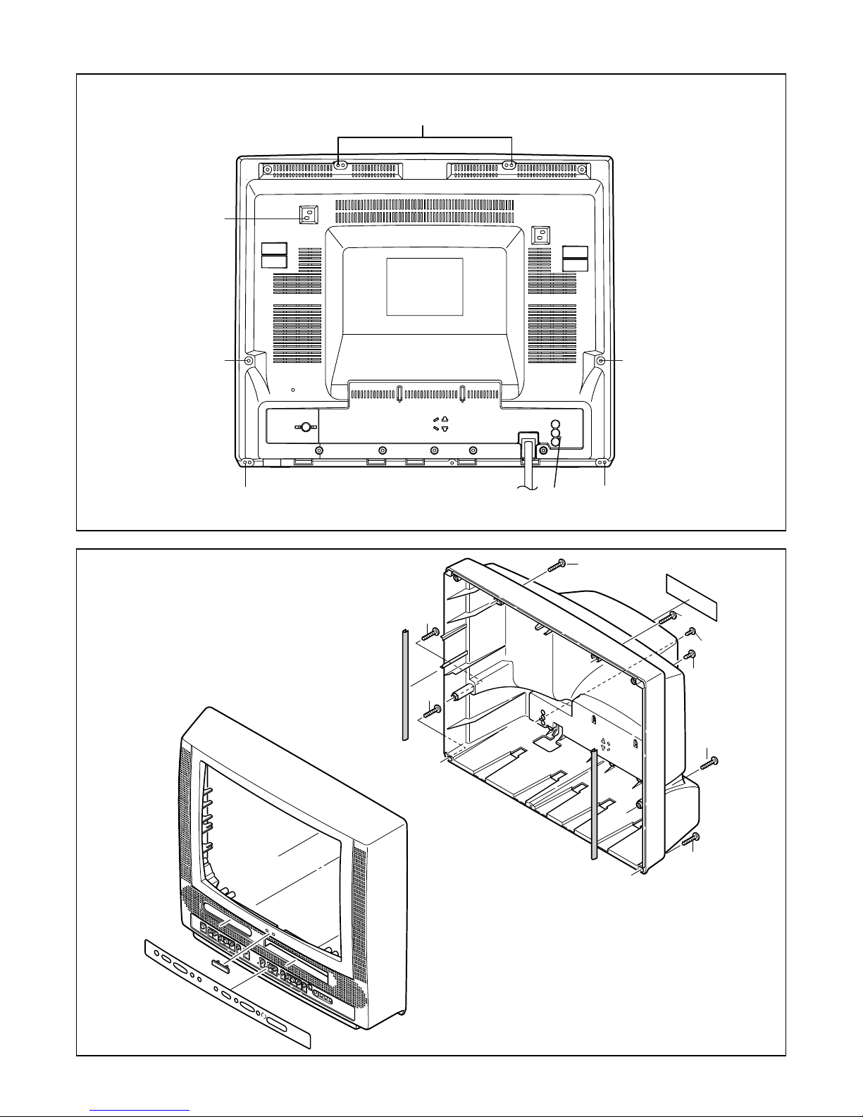
S-2
S-1
[1] REAR CABINET
S-1
S-1
S-1
S-1
S-3
S-1
S-1
Fig. 1
S-1
S-1
S-3
S-2
S-1
S-1
[1] REAR CABINET
Fig. 2
1-3-3 TD857DC
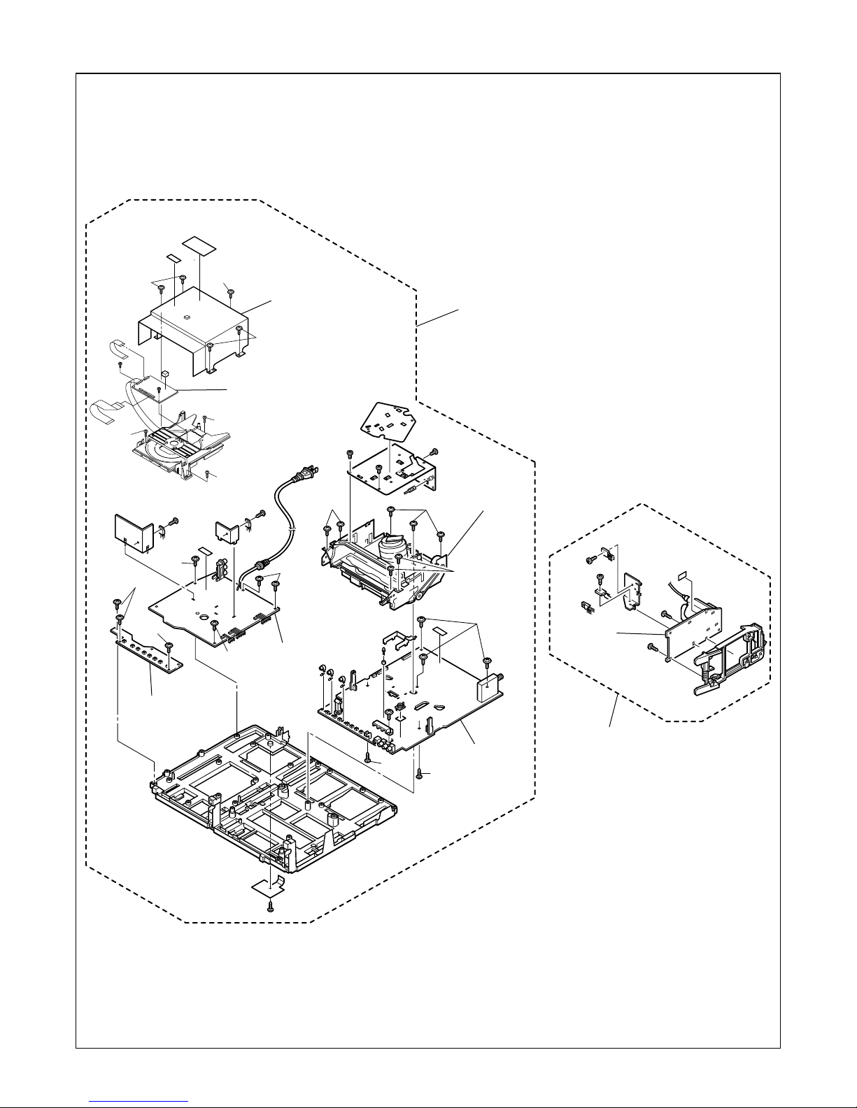
S-6
S-5
S-5
[5] Shield Box
[3] Tray Chassis Unit
S-5
[6] DVD
Mechanism
S-6
S-8
S-9
S-9
[9] Function
CBA
S-6
S-8
S-8
[8] Power
Supply/
AV CBA
S-10
S-11
S-10
S-11
[10] Deck
Assembly
S-10
S-12
[11] Main
CBA
H.V. CBA
[2] H.V. CBA
(wih Holder)
Fig. 3
1-3-4 TD857DC
S-4
Anode Cap
CRT CBA
S-7
CN301
S-4
CN201
[4] CRT
S-7
[7] DVD Main
CBA Unit
S-4
S-4
Fig. 4
Slide
B
Pickup Unit
View for A
DVD Mechanism
A
Short the three short
lands by soldering
View for B
Fig. 5
1-3-5 TD857DC
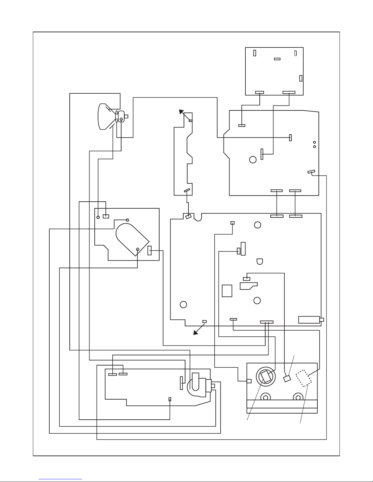
DVD MAIN CBA
FACTORY USE
ONLY
ANODE
CRT
GND
CL501
CN501
FUNCTION CBA
CRT CBA
SCREEN
FOCUS
CL504A
TO SPEAKER
CN2801
CN2805
CN1805
CN2401
MAIN CBA
CL1403
CL1401
CN601
CN2402
CN401
CN2601
AC CORD
POWER SUPPLY/
AV CBA
CN2803
CN1804
CN2602
CN2804
CN1803
CL503A
CL502A
CL501A
H.V. CBA
TO SPEAKER
CN571
CN1802
CL1201
FE HEAD
CYLINDER
ASSEMBLY
CL1402
CN1301
AC HEAD
ASSEMBLY
DECK ASSEMBLY
CAPSTAN
MOTOR
TUNER
Fig. 6
1-3-6 TD857DC
ELECTRICAL ADJUSTMENT INSTRUCTIONS
General Note:
"CBA" is abbreviation for "Circuit Board
Assembly."
NOTE:
Electrical adjustments are required after replacing
circuit components and certain mechanical parts.
It is important to perform these adjustments only
after all repairs and replacements have been completed.
Also, do not attempt these adjustments unless the
proper equipment is available.
Test Equipment Required
1. NTSC Pattern Generator (Color Bar W/White Window, Red Color, Dot Pattern, Gray Scale, Monoscope, Multi-Burst)
2. AC Milli Voltmeter (RMS)
3. Alignment Tape (VFMS0001H6), Blank Tape
4. DC Voltmeter
5. Oscilloscope: Dual-trace with 10:1 probe,
V-Range: 0.001~50V/Div,
F-Range: DC~AC-60MHz
6. Frequency Counter
7. Plastic Tip Driver
8. Color Analyzer
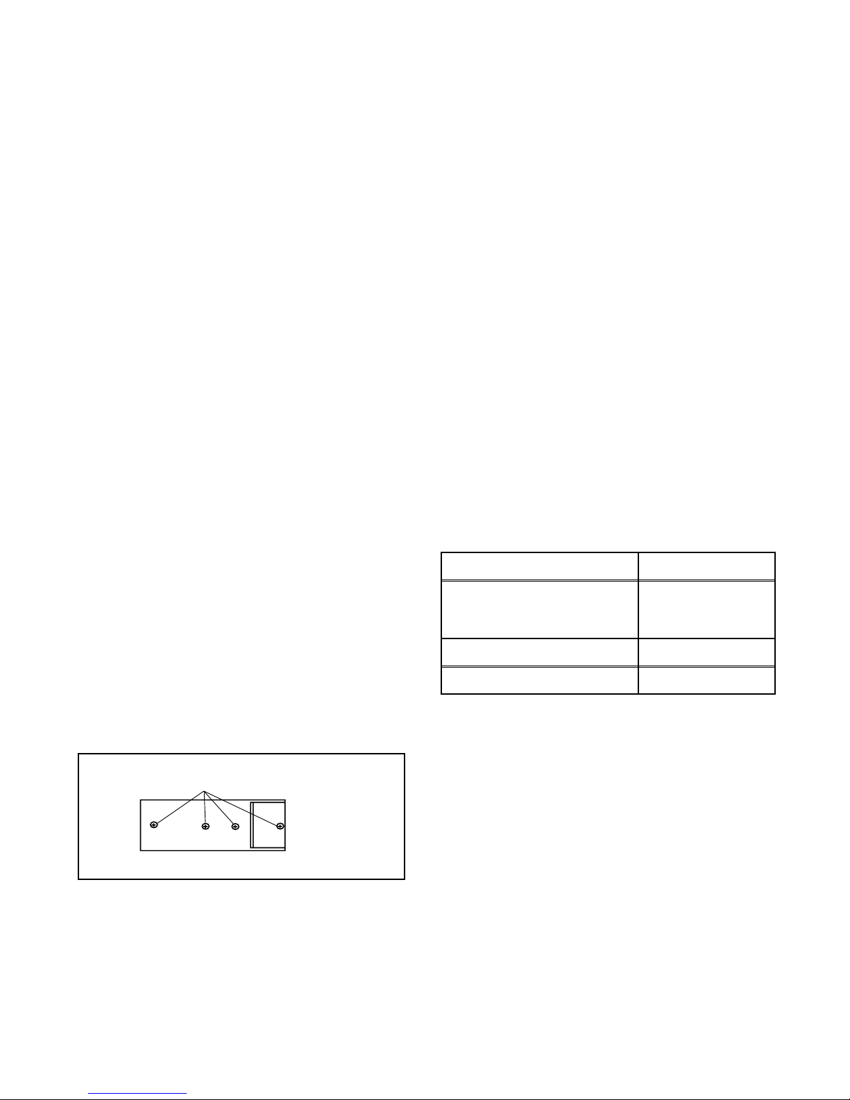
How to make service remote control
unit:
1. Prepare remote control unit (ID No. NE206UD, Part
No. 4835 218 37345). Remove 4 screws from the
back lid (Fig. 1-1).
SCREW
How to Set Up the Service Mode:
1. Turn the power on. (Use main power on the TV
unit.)
2. To enter the TV mode, press "CH o" or "CH p"
button on the TV unit.
3. Press "DISC MENU" button on the service remote
control unit. (Version of micro computer will display
on the CRT. (Ex: 057-001)
X-Ray Protection Test
X-Ray protection test should be done when replacing
any parts of this chassis.
1. Short test points J551 and J552 (on H.V. CBA).
2. Confirm that the main power turns off.
3. If the main power does not turn off, then replace
the following parts (D591, Q591, R592, R593,
R594 and IC1201).
4. Perform steps 1 to 3 again.
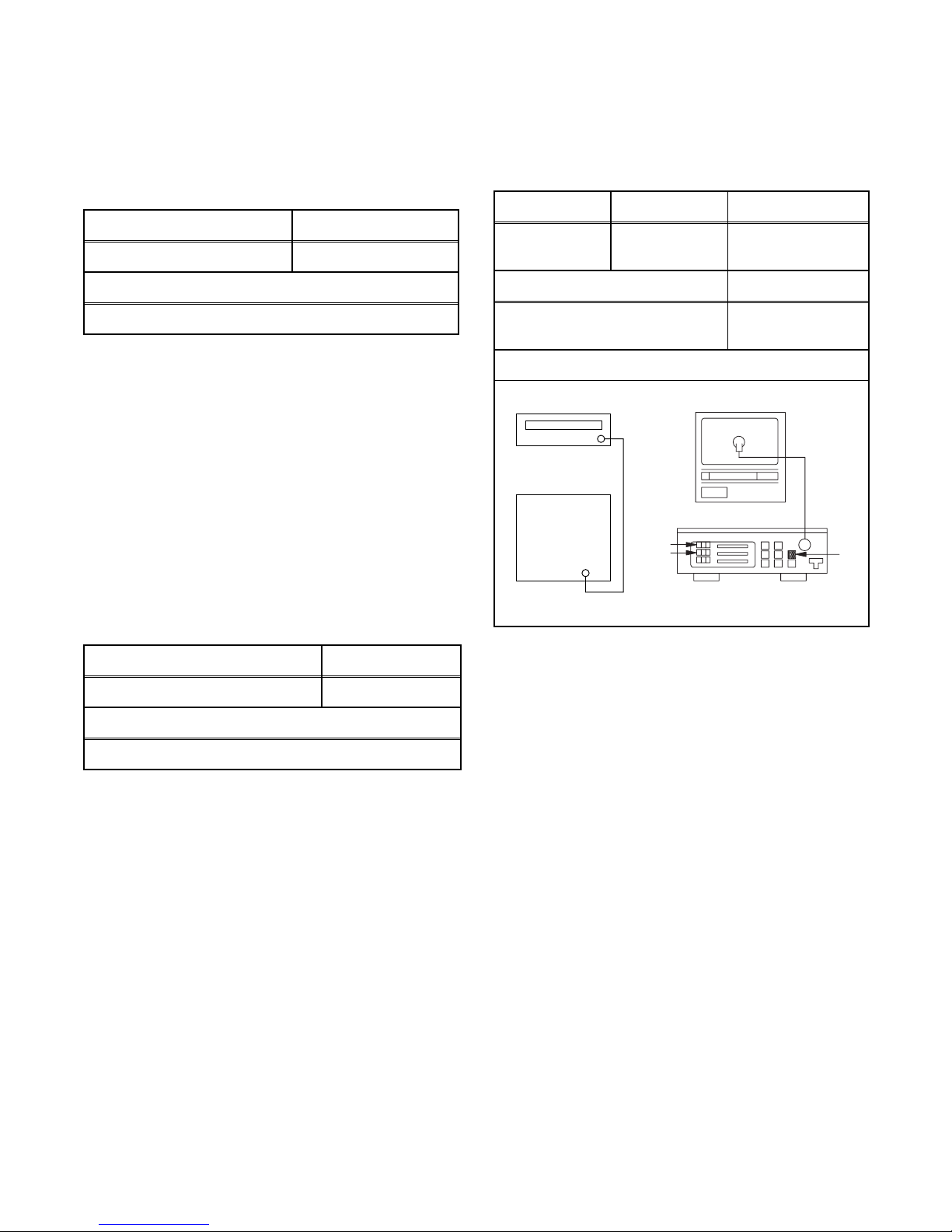
1. DC 114V (+B) Adjustment
Purpose: To obtain correct operation.
Symptom of Misadjustment: The picture is dark and
unit does not operate correctly.
Test Point Adj. Point
J553(+B)
HEAT SINK (on H.V. CBA)
(GND)
M. EQ. Spec.
DC Voltmeter +114±0.5V DC
Notes: J553(+B), HEAT SINK --- H.V. CBA
VR2601 --- Power Supply/AV CBA
1. Connect the unit to AC power outlet.
2. Connect DC Volt Meter to J553(+B) and HEAT
SINK (on H.V. CBA) (GND).
3. Adjust VR2601 so that the voltage of J553(+B)
becomes +114±0.5V DC.
VR2601
Remote control unit (Bottom)
2. Cut off pin 10 of the remote control microprocessor
and short circuit pins 10 and 17 of the microprocessor with a jumper wire.
Fig. 1-1
1-4-1 TD857EA
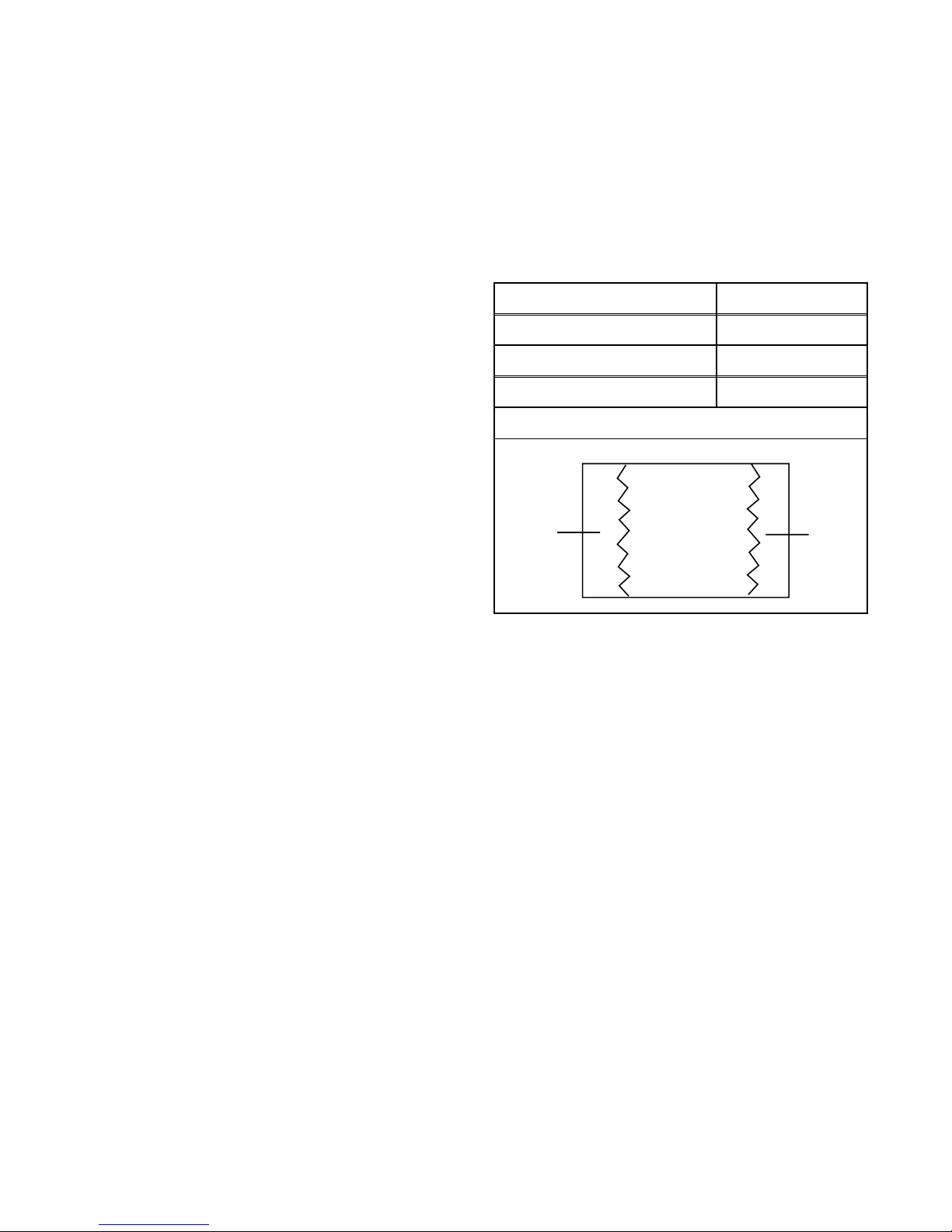
2. H Adjustment
Purpose: To get correct horizontal position and size of
screen image.
Symptom of Misadjustment: Horizontal position and
size of screen image may not be properly displayed.
Test Point Adj. Point Mode
R583 CH o / p buttons Video
M. EQ. Spec.
1. Connect Oscilloscope to D1304 (Cathode).
2. Input a color bar signal from RF input.
Enter the Service mode. (See page 1-4-1.)
3. Press "0" button on the service remote control unit
and select C-TRAP Mode.
4. Press CH o / p buttons on the service remote
control unit so that the carrier leakage B-Out
(3.58MHz) value becomes minimum on the oscilloscope.
5. Turn the power off and on again.
Frequency Counter 15.734kHz±300Hz
Note: R583 --- H.V. CBA
1. Connect frequency counter to R583.
2. Operate the unit for at least 20 minutes.
3. Enter the Service mode. (See page 1-4-1.) Press
"2" button on the service remote control unit and
select H-ADJ mode.
4. Press "CH o / p" buttons on the service remote
control unit so that the display will change "0" to
"7." At this moment, choose display "0" to "7" when
the frequency counter display is closest to
15.734kHz±300Hz.
5. Turn the power off and on again.
3. C-Trap Adjustment
Purpose: To get minimum leakage of the color signal
carrier.
Symptom of Misadjustment: If C-Trap Adjustment is
incorrect, stripes will appear on the screen.
Test Point Adj. Point Input
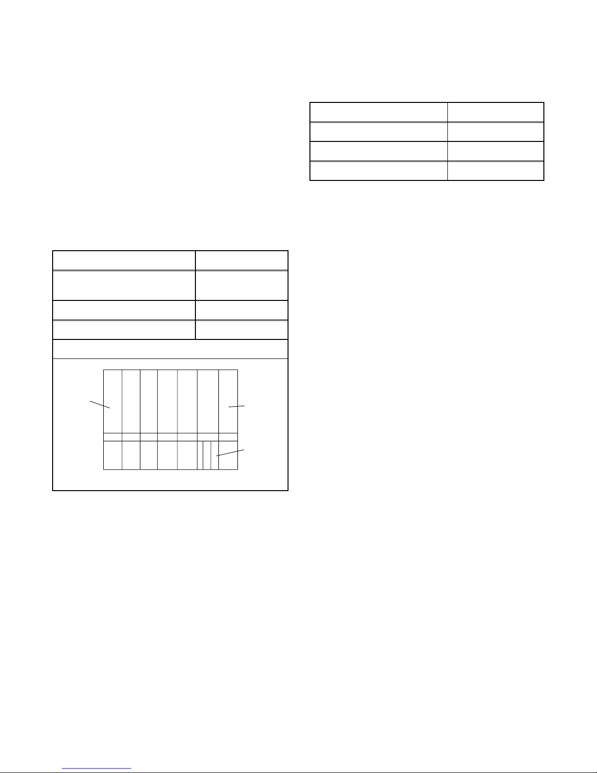
4. V. Size Adjustment
Purpose: To obtain correct vertical height of screen
image.
Symptom of Misadjustment: If V. Size is incorrect,
vertical height of image on the screen may not be
properly displayed.
Adj. Point Input
CH o / p buttons Monoscope
M. EQ. Spec.
Pattern Generator 90±5%
1. Enter the Service mode. (See page 1-4-1.)
Press "9" button on the service remote control unit
and select V-S mode. (Press "9" button then display will change to V-P and V-S).
2. Input monoscope pattern.
3. Press "CH o / p" buttons on the service remote
control unit so that the monoscope pattern is
90±5% of display size and the circle is round.
D1304
(Cathode)
(B-OUT)
minimum
Note: D1304 (Cathode) (B-Out)--- Main CBA
CH o / p
buttons
M. EQ.
Oscilloscope,
Pattern Generator
Figure
Color Bar
Fig. 2
1-4-2 TD857EA
5. V. Shift Adjustment
7. Cut-off Adjustment
Purpose: To obtain correct vertical position of screen
image.
Symptom of Misadjustment: If V. shift is incorrect,
vertical position of image on the screen may not be
properly displayed.
Adj. Point Input
CH o / p buttons Monoscope
M. EQ.
Pattern Generator
1. Enter the Service mode. (See page 1-4-1.)
Press "9" button on the service remote control unit
and select V-P mode. (Press "9" button then display will change to V-P and V-S).
2. Input monoscope pattern.
3. Press "CH o / p" buttons on the service remote
control unit so that the top and bottom of the monoscope pattern are equal to each other.
6. H. Shift Adjustment
Purpose: To adjust the beam current of R, G, B, and
screen voltage.
Symptom of Misadjustment: White color may be
reddish, greenish or bluish.
Adj. Point Mode Input
Screen-Control Ext.
M. EQ. Spec.
Pattern Generator
Color Analyzer
Figure
PATTERN
GENERATOR
Black Raster /
White Raster
See Reference
Notes below
Purpose: To obtain correct horizontal position and
size of screen image.
Symptom of Misadjustment: Horizontal position and
size of screen image may not be properly displayed.
Adj. Point Input
CH o / p buttons Monoscope
M. EQ.
Pattern Generator
1. Enter the Service mode. (See page 1-4-1.)
Press "8" button on the service remote control unit
and select H-P mode.
2. Input monoscope pattern.
3. Press "CH o / p" buttons on the service remote
control unit so that the left and right side of the
monoscope pattern are equal to each other.
4. Turn the power off and on again.
EXT. INPUT
Color Analyzer
Fig. 3
Notes: Screen Control FBT --- H.V. CBA
FBT= Fly Back Transformer
Use the service remote control unit
1. Degauss the CRT and allow CRT to operate for 20
minutes before starting the alignment.
2. Input the Black raster signal from EXT. input.
3. Enter the Service mode. (See page 1-4-1.)
4. Press the "VOL p" button.
(Press "VOL p" then display will change CUT OFF/
DRIVE, 7Fh adjustment and DVD-KEY).
5. Choose CUT OFF/DRIVE mode then press "1" button. This adjustment mode is CUT OFF (R).
6. Increase the screen control so that the horizontal
line just appears on the CRT.
7. Press the "CH o / p" button until the horizontal line
becomes white.
8. Choose CUT OFF/DRIVE mode then press "2" button. This adjustment mode is CUT OFF (G). Press
"CH o / p" until the horizontal line becomes white.
9. Choose CUT OFF/DRIVE mode then press "3" button. This adjustment mode is CUT OFF (B). Press
"CH o / p" until the horizontal line becomes white.
10.Choose CUT OFF/DRIVE mode then press "4" button.
11.Input the White Raster Signal from Video In.
1-4-3 TD857EA
12.Set the color analyzer to the CHROMA mode and
after zero point calibration, bring the optical receptor to the center on the tube surface (CRT).
13.Adjust the RED DRIVE as needed with the CH o /
p buttons to get the following value, X= 286, Y=
294.
14.Choose CUT OFF/DRIVE mode then press "5."
Adjust the BLUE DRIVE as needed with the CH o /
p buttons to get the following value, X= 286.
15.Turn the power off and on again.
8. Sub-Brightness Adjustment
Purpose: To get proper brightness.
Symptom of Misadjustment: If Sub-Brightness is
incorrect, proper brightness cannot be obtained by
adjusting the Brightness Control.
Adj. Point Input
CH o / p
buttons
M. EQ. Spec.
Pattern Generator See below
Figure
SMPTE 7.5IRE
9. Focus Adjustment
Purpose: Set the optimum Focus.
Symptom of Misadjustment: If Focus Adjustment is
incorrect, blurred images are shown on the display.
Adj. Point Input
Focus Control Monoscope
M. EQ. Spec.
Pattern Generator See below.
Notes: Focus VR (FBT) --- H.V. CBA
FBT= Fly Back Transformer
1. Operate the unit more than 30 minutes.
2. Face the unit to the East and degauss the CRT
using a degaussing coil.
3. Input the monoscope pattern.
4. Adjust the Focus Control on the FBT to obtain a
clear picture.
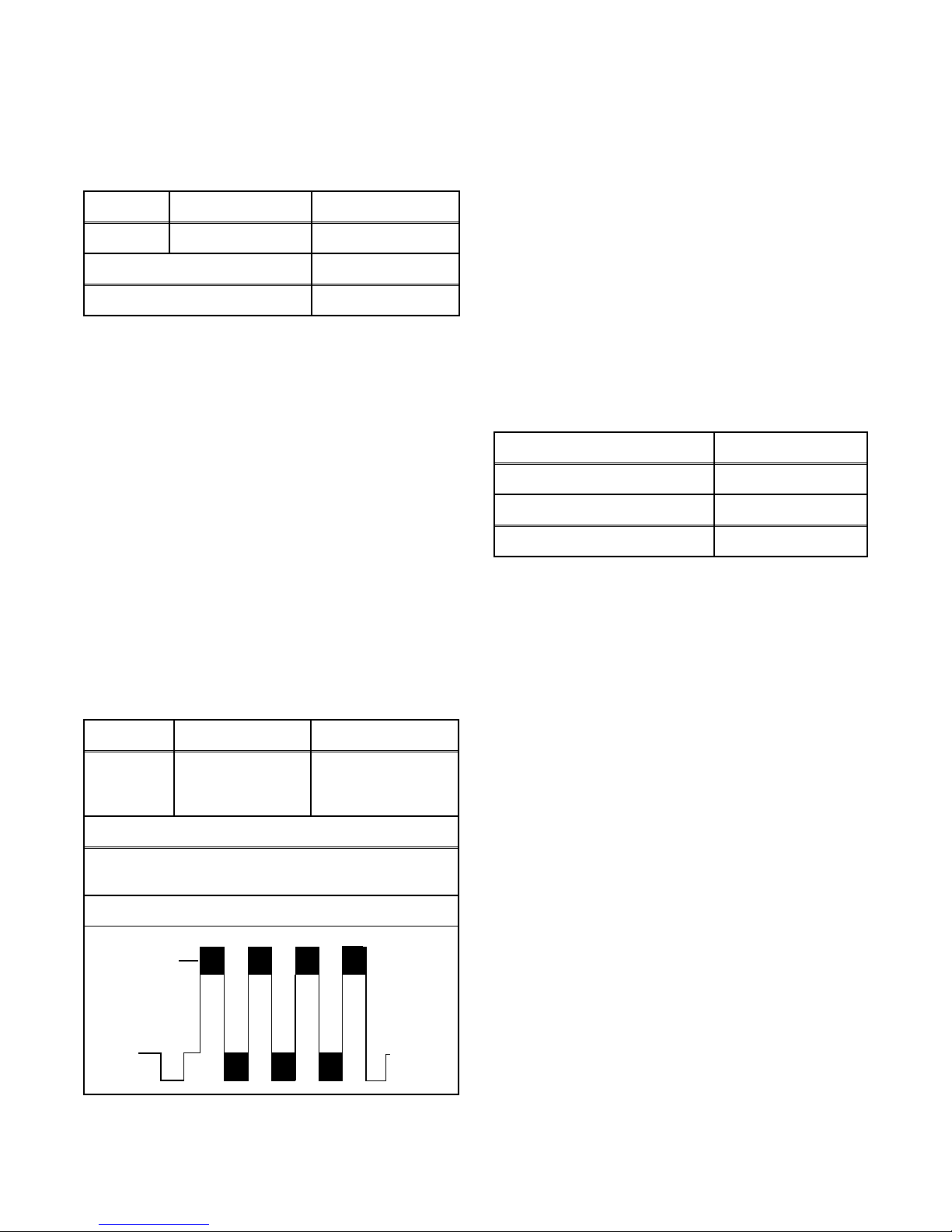
10. SIF Adjustment
Purpose: To set the SIF (Sound Intermediate Fre-
quency).
Symptom of Misadjustment: Audio may not sound
correctly.
Note: This adjustment automatically done by the
chrominance IC (IC1301).
White
Note: SMPTE Setup level --- 7.5 IRE
1. Enter the Service mode. (See page 1-4-1.)
Then input SMPTE signal from RF input.
2. Press "PICTURE" button. (Press "PICTURE" button then display will change B R T, C N T, COL, T N
T and V-T ). Select BRT and press "CH o / p" buttons so that the bar is just visible (See above figure).
3. Turn the power off and on again.
Black
This bar
just
visible
Fig. 4
11. CCS Text Box Location
Note: This adjustment automatically done by the
microcomputer.
1-4-4 TD857EA
12. Head Switching Position Adjustment
Purpose: Determine the Head Switching Point during
Playback.
Symptom of Misadjustment: May cause Head
Switching Noise or Vertical Jitter in the picture.
Note: Unit reads Head Switching Position automati-
cally and displays it on the screen (Upper Left Corner).
1. Playback test tape (VFMS0001H6).
2. Enter the Service mode. (See page 1-4-1.)
Then press the "5" button on the service remote
control unit.
3. The Head Switching position will display on the
screen; if adjustment is necessary follow step 4.
6.5H(412.7µs) is preferable.
4. Press "CH o" or "CH p" button on the service
remote control unit if necessary. The value will be
changed in 0.5H steps up or down. Adjustable
range is up to 9.5H. If the value is beyond adjustable range, the display will change as:
Lower out of range: 0.0H
Upper out of range: -.-H
5. Turn the power off and on again.
The following 2 adjustments normally are not
attempted in the field. They should be done
only when replacing the CRT, then adjust as a
preparation.
13. Purity Adjustment
Purpose: To obtain pure color.
Symptom of Misadjustment: If Color Purity Adjust-
ment is incorrect, large areas of color may not be
properly displayed.
Adj. Point Input
Deflection Yoke Purity Magnet Red Color
M. EQ. Spec.
Pattern Generator See below.
Figure
GREEN
RED
BLUE
Fig. 5
1. Set the unit facing East.
2. Operate the unit for over 30 minutes before adjusting.
3. Fully degauss the unit using an external degaussing coil.
4. Set the unit to the AUX mode, which is located
before CH2, then input a red raster from video in.
5. Loosen the screw on the Deflection Yoke Clamper
and pull the Deflection Yoke back away from the
screen. (See Fig. 6.)
6. Loosen the Ring Lock and adjust the Purity Magnets so that a red field is obtained at the center of
the screen. Tighten Ring Lock. (See Fig. 5,6.)
7. Slowly push the Deflection Yoke toward the bell of
the CRT and set it where a uniform red field is
obtained.
8. Tighten the clamp screw on the Deflection Yoke.
1-4-5 TD857EA
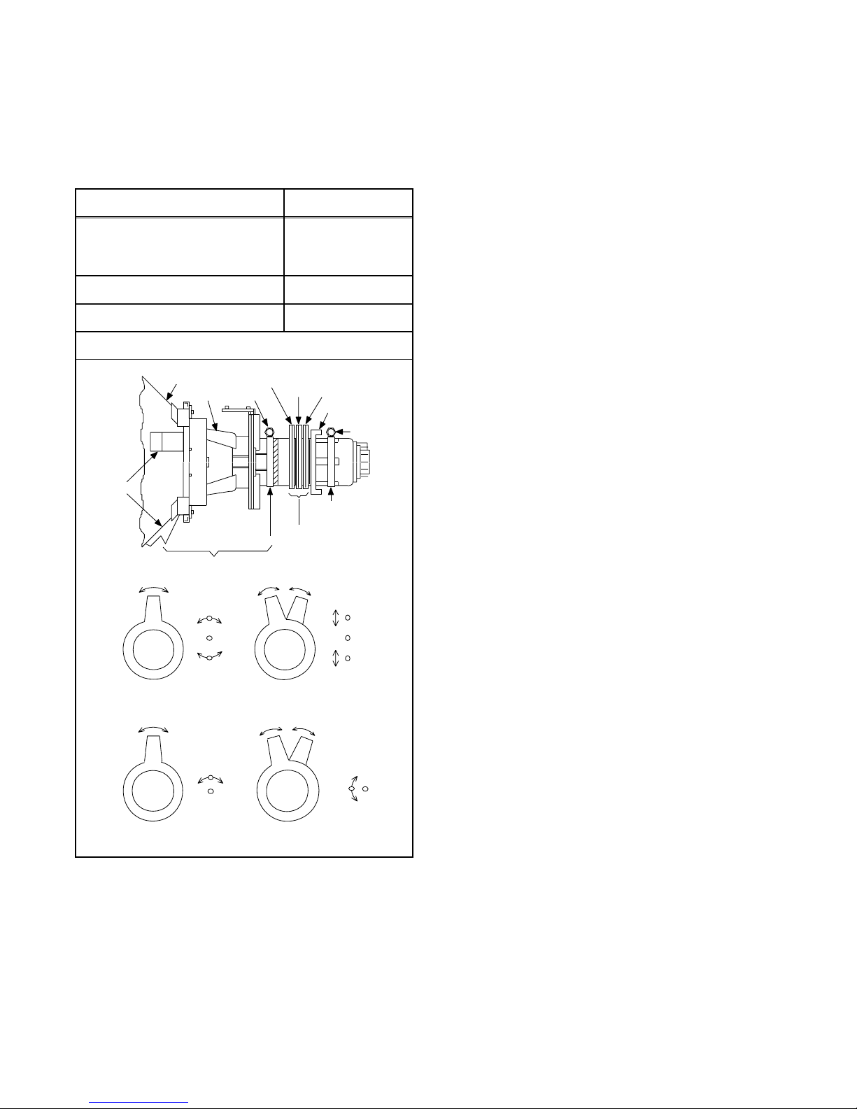
14. Convergence Adjustment
Purpose: To obtain proper convergence of red, green
and blue beams.
Symptom of Misadjustment: If Convergence Adjust-
ment is incorrect, the edge of white letters may have
color edges.
Adj. Point Input
5. Remove the DY Wedges and slightly tilt the Deflection Yoke horizontally and vertically to obtain the
best overall convergence.
6. Fix the Deflection Yoke by carefully inserting the
DY Wedges between CRT and Deflection Yoke.
C.P. Magnet (RB),
C.P. Magnet (RB-G),
Dot Pattern or
Deflection Yoke
M. EQ. Spec.
Pattern Generator See below.
Figure
CRT
COIL
DY WEDGE
COIL CLAMPER
DEFLECTION YOKE
PURITY
SCREW
RB
C.P. MAGNET
CLAMPER
C.P. MAGNET
C.P. MAGNET (RB)
R
Crosshatch
RB-G
RING LOCK
SCREW
Fig. 6
R
G
B
G
B
Fig. 7
C.P. MAGNET (RB-G)
RB
RB
G
G
Fig. 8
1. Set the unit to the AUX mode which is located
before CH2, then input a dot or crosshatch pattern.
2. Loosen the Ring Lock and align red with blue dots
or crosshatch at the center of the screen by rotating (RB) C.P. Magnets. (See Fig. 7.)
3. Align red / blue with green dots at the center of the
screen by rotating (RB-G) C.P. Magnet.
(See Fig. 8.)
4. Fix the C.P. Magnets by tightening the Ring Lock.
1-4-6 TD857EA
Adjustment Points and Test Points
H.V. CBA
UPPER
FOCUS VR
LOWER
SCREEN VR
VR2601
+B ADJ
J553
+B
R583
H ADJ.
Power Supply/AV CBA
1-4-7 TD857EA
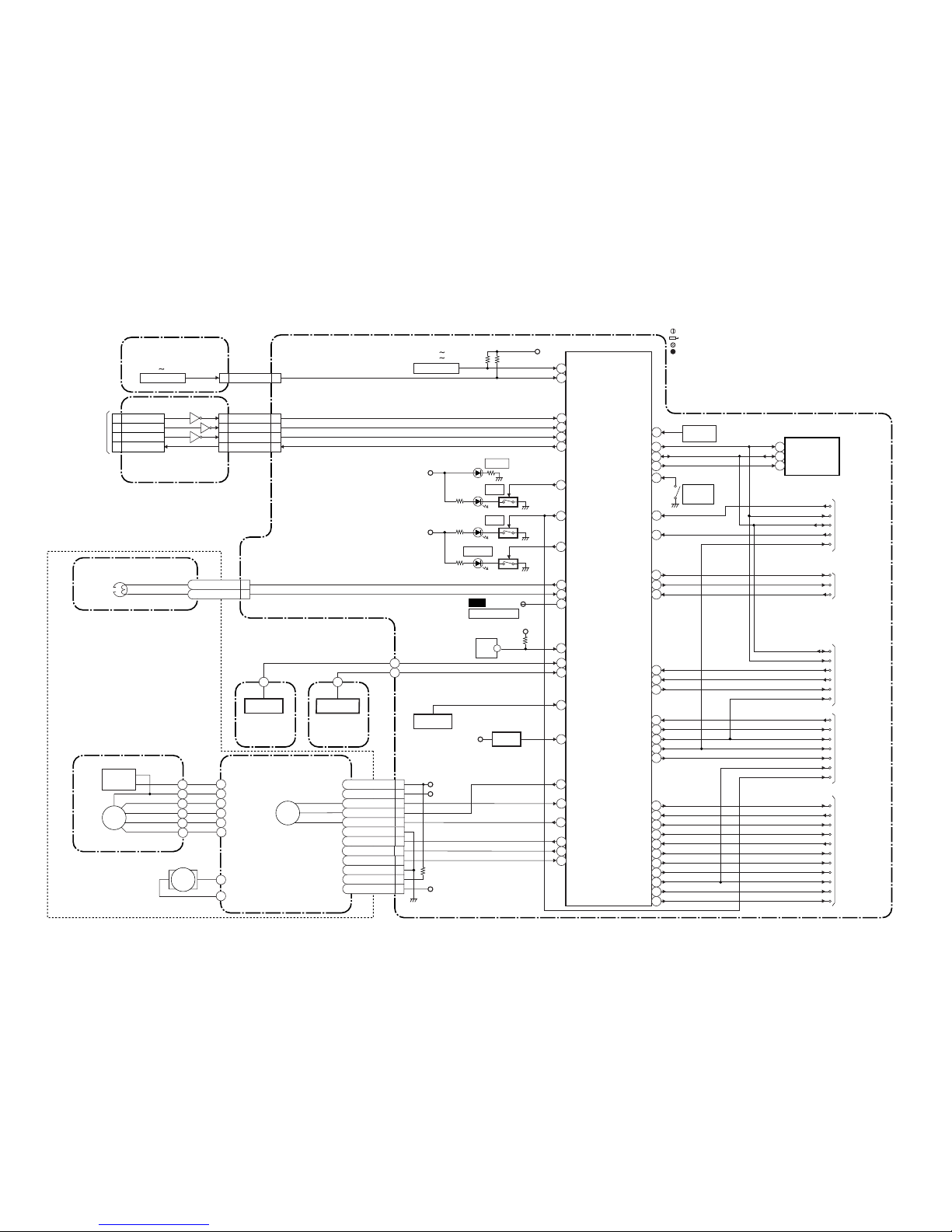
CONTROL
HEAD
CL1402
AC HEAD ASSEMBLY
MAIN CBA
POWER SUPPLY / AV CBA
RF-SW
T-REEL
DV-SYNC
C-SYNC
C-SYNC
V-ENV
CTL(+)
D1224 S-LED
D1204 REC
D1216 DVD
D1217
TV/VCR
Q1210
Q1211
Q1207
P-ON+5V
REC-LED
KEY0
RS1201
REMOTE
SENSOR
KEY1
DVD-H
TV/VCR-LED
RESET
ROTA
D-REC-H
D-REC-H
REC-SAFETY
A-MUTE
SCL
REMOTE
SDA
A-MUTE
CTL(-)
RF-SW
DV-SYNC
V-ENV
ROTA
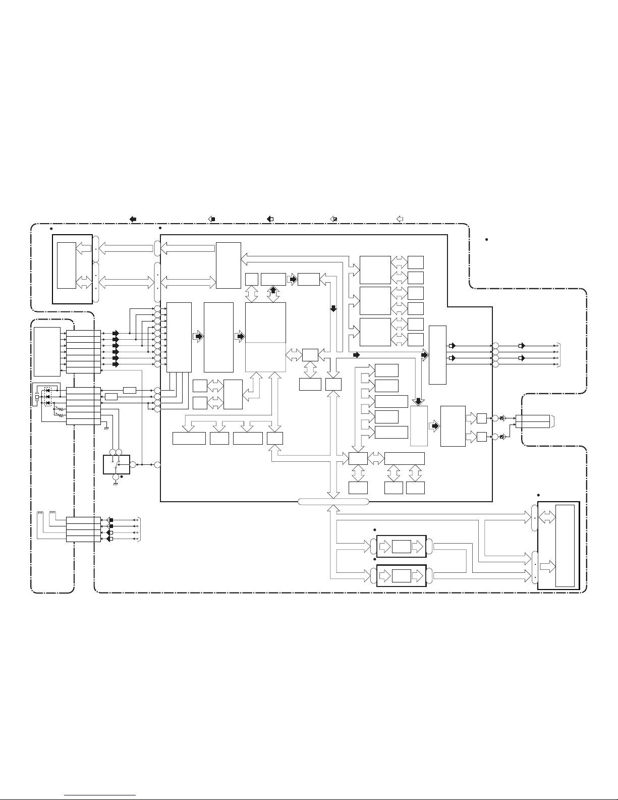
IC1201
(SERVO/SYSTEM CONTROL)
AL+5V
AL+5V
94
95
80
34
18
15
10
13
74
33
8
44
65
72
CTL-AMP-OUT
DVD-REMOTE
97
CTL-AMP-OUT
TP1201
(DECK ASSEMBLY)
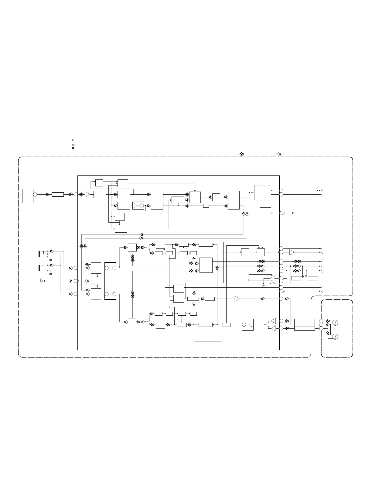
Servo/System Control Block Diagram
BLOCK DIAGRAMS <TV/VCR Section>
T-REEL
Q1206
Q1205
RESET
TIMER+5V
ST/SAP-MODE
4
NORMAL-H
22
28
EXT-H
29
RENTAL
30
SPL-PLAY
SP/LP/SLP
EXT-H
RENTAL
SPL-PLAY
32
REC/EE/PB
REC/EE/PB
27
VOL-CONT
VOL-CONT
11
EXT-H
A-MUTE
JACK-MUTE
JACK-MUTE
DVD-MAIN-POWER
67
SW1211
REC
SAFETY
FROM/TO
VIDEO BLOCK
FROM/TO
AUDIO BLOCK
FROM/TO
Hi-Fi AUDIO
BLOCK
1-5-1 1-5-2 TD857BLS
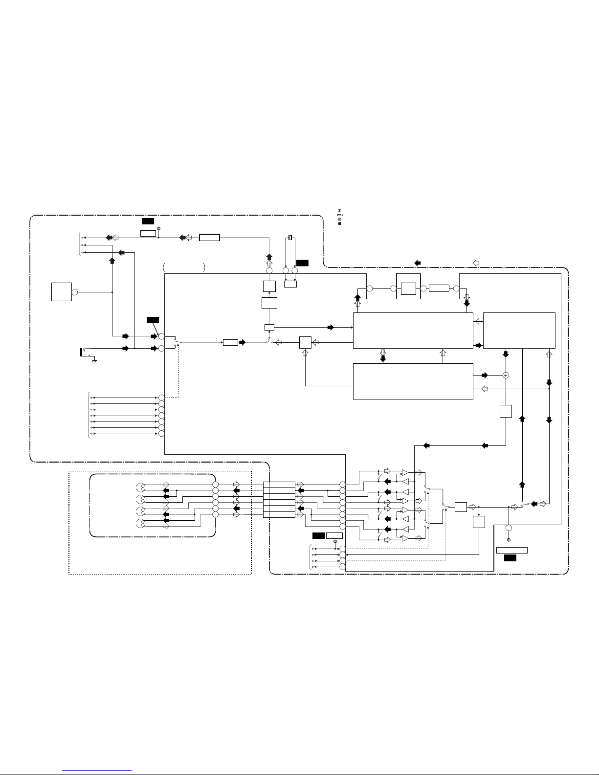
SCL
(MEMORY)
SDA
6
5
P-DOWN
84
P-ON-H
P-DOWN
P-ON-H
31
LD-SW1
I2C-OPEN
45
71
AL+5V
SW1212
LD-SW
CS7
FROM/TO
POWER
SUPPLY BLOCK
SDA
SCL
FROM/TO
CHROMA
BLOCK
IC1202
WF3
ENV-DET
17
V-H-SW
ENV-DET
V-H-SW
16
SDA
SCL
Hi-Fi-H-SW
ST/SAP-IN
NORMAL-H
DVD-MAIN-POWER
Hi-Fi-H-SW
19
26
48
21
DVD-H
DVD-A-MUTE
42
5
KEY SWITCH
SW1201 SW1203,
SW1206 SW1210
5 5KEY1
CN2805
CN2803
CN1805
KEY SWITCH
SW2401 SW2408
14
25
12SDATA
1220 SDATA
FROM/TO
DVD SYSTEM
CONTROL
/SERVO BLOCK
<DVD SECTION>
CN401
CN2402
6
CN1804
13SCLK
14CS
15
DVD-REMOTE
M
1P-ON+12V
5C-CONT
6
FG-GND
7LD-CONT
CAPSTAN
MOTOR
CAPSTAN MOTOR
P-ON+5V
D/L+15V
P-ON+12V
10M-GND
11D/L+12V
9D-PFG
12D/L+15V
END-SENS.
Q201
SENSOR CBA
(END-SENSOR)
ST-SENS.
Q202
SENSOR CBA
(ST-SENSOR)
21 SCLK
18 CS
22
DVD-REMOTE
52
51
50
SDATA
SCLK
CS
69
DVD-A-MUTE
5CTL(+)
6CTL(-)
8D-CONT
4
C-F/R
3C-FG
2P-ON+5V(3)
66
87
76
82
77
90
C-F/R
C-FG
C-CONT
LD-CONT
D-CONT
D-PFG
CL1201
M
LOADING
MOTOR
CYLINDER ASSEMBLY
M
DRUM
MOTOR
PG
SENSOR
9
7
ST-SENS.
END-SENS.
13
14
15
AFT
AFT
D-REC-H
SP/LP/SLP
FUNCTION CBA
Q2621
Q2622
Q2623
NOTE FOR WIRE CONNECTORS:
1. PREFIX SYMBOL "CN" MEANS CONNECTOR.
(CAN DISCONNECT AND RECONNECT.)
2. PREFIX SYMBOL "CL" MEANS WIRE-SOLDER
HOLES OF THE PCB.
(WIRE IS SOLDERED DIRECTLY.)
TEST POINT INFORMATION
:INDICATES A TEST POINT WITH A JUMPER WIRE ACROSS A HOLE IN THE PCB.
:USED TO INDICATE A TEST POINT WITH A COMPONENT LEAD ON FOIL SIDE.
:USED TO INDICATE A TEST POINT WITH NO TEST PIN.
:USED TO INDICATE A TEST POINT WITH A TEST PIN.
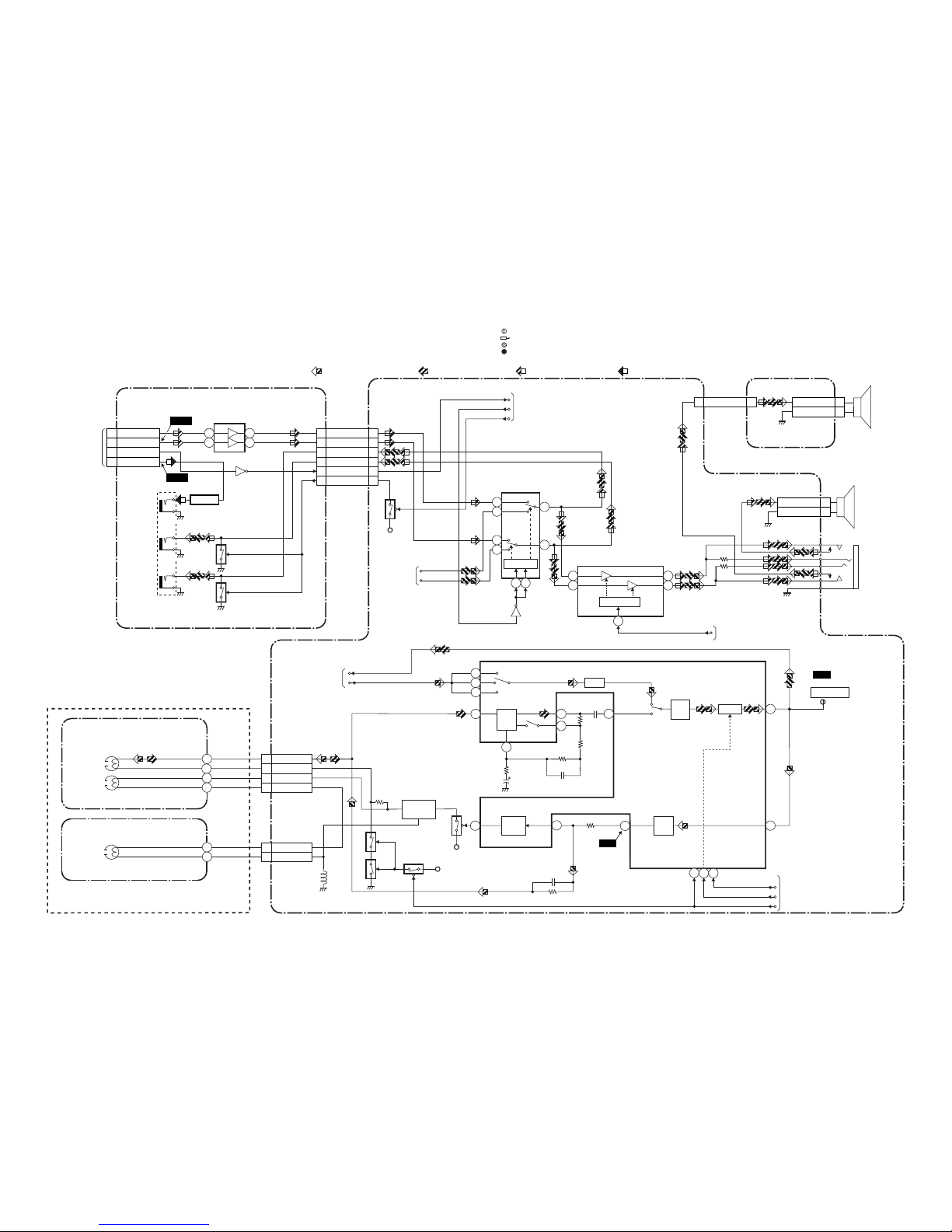
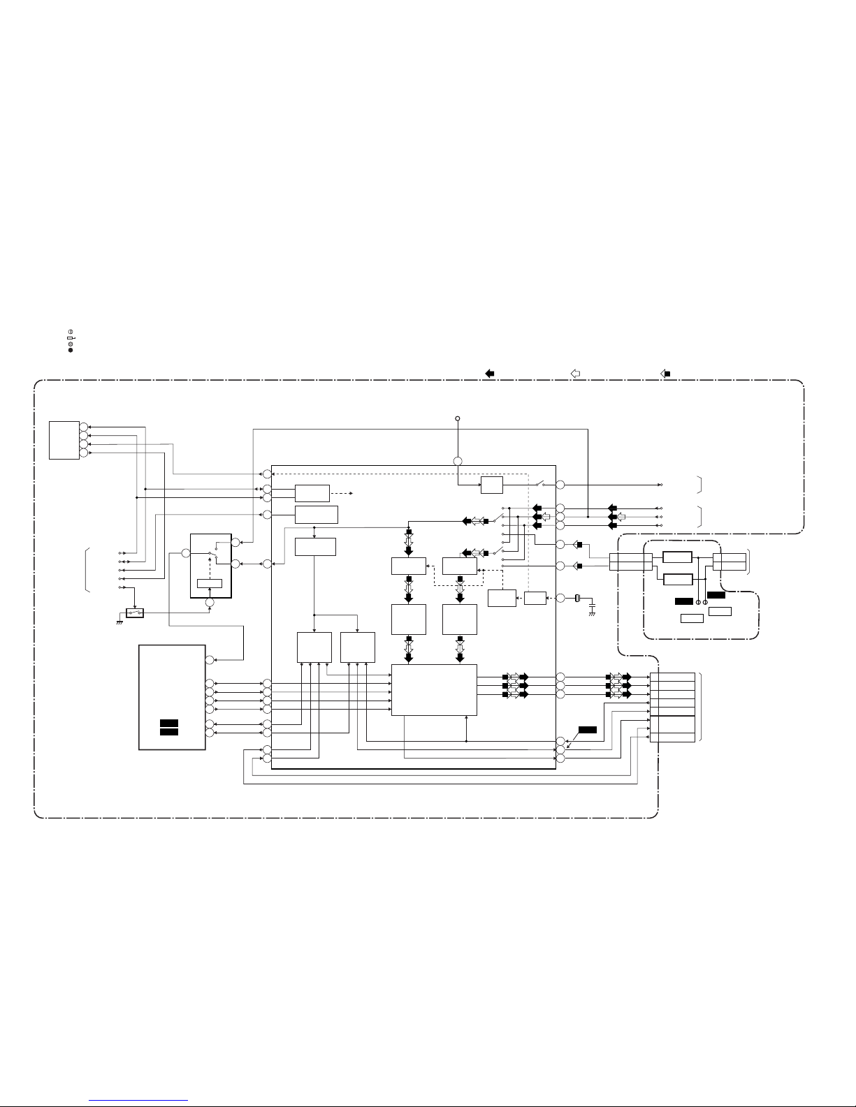
Video Block Diagram
1-5-3 1-5-4 TD857BLV
REC VIDEO SIGNAL PB VIDEO SIGNAL MODE: SP/REC
LUMINANCE
SIGNAL PROCESS
MAIN CBA
CL1401
Q1401
TP1402
V-OUT
V-AGC
R P
FBC
Y/C
MIX
CCD 1H
DELAY
R
P
DOC YNR Y/C COMB
CHROMINANCE
SIGNAL PROCESS
IC1401
VIDEO/AUDIO
SIGNAL PROCESS
35
42
38
17
CHARA
MIX
6dB
AMP
VXO
ENV
DET
AGC
AMP
HPF
FROM
SERVO/SYSTEM
CONTROL BLOCK
RF-SW
TP1401
WF1
TP1403
HA-MONITOR
BUFFER
DV-SYNC
SP/LP/SLP
ROTA
DV-SYNC
ROTA
14
36
16
71
39
59
73
SPL-PLAY
REC/EE/PB
RENTAL
SPL-PLAY
REC/EE/PB
RENTAL
42
EXT-H
74
45 47 49 44
Q1402
WF6
WF5
WF4
WF2
L
R
VIDEO (R)-1 HEAD
VIDEO (L)-1 HEAD
(DECK ASSEMBLY)
V(R)-1
V-COM
V(L)-1
9
8
7
V(L)-2
V-COM
V(R)-2
6
5
4
13
88
89
90
91
FROM/TO
SERVO/SYSTEM
CONTROL BLOCK
CYLINDER ASSEMBLY
R
L
RF-SW
93
V-ENV
V-H-SW
ENV-DET
ENV-DET
VIDEO (L)-2 HEAD
VIDEO (R)-2 HEAD
15
94
82
83
84
85
SP
EP
TO
CHROMA
BLOCK
62 61
X1401
3.58MHz
VIDEO
V-OUT
TVEXT-V-IN
VIDEO
TU1001
(TUNER UNIT)
JK1701
VIDEO-IN
SP/LP/SLP
BUFFER
NOTE FOR WIRE CONNECTORS:
1. PREFIX SYMBOL "CN" MEANS CONNECTOR.
(CAN DISCONNECT AND RECONNECT.)
2. PREFIX SYMBOL "CL" MEANS WIRE-SOLDER
HOLES OF THE PCB.
(WIRE IS SOLDERED DIRECTLY.)
TEST POINT INFORMATION
:INDICATES A TEST POINT WITH A JUMPER WIRE ACROSS A HOLE IN THE PCB.
:USED TO INDICATE A TEST POINT WITH A COMPONENT LEAD ON FOIL SIDE.
:USED TO INDICATE A TEST POINT WITH NO TEST PIN.
:USED TO INDICATE A TEST POINT WITH A TEST PIN.
Audio Block Diagram
BLOCK DIAGRAM FOR SECTION 2 (DECK MECHANISM)
MAIN CBA
POWER SUPPLY / AV CBA
PB-AUDIO SIGNAL
DVD AUDIO SIGNAL
REC-AUDIO SIGNAL
1-5-5
IC1401
TD857BLA1-5-6
BIAS
OSC
Q1872
P-ON+5V
P-ON+5V
Q1871
Q1873
Q1874
Q1875
(AUDIO PROCESS)
N-A-IN
N-A-OUT
TP1802
NA-IN-YCA
AUDIO
HEAD
AC HEAD ASSEMBLY
A-COM
A-PB/REC
CL1402
CN1804CN2803
AUDIO
ERASE
HEAD
AE-H
AE-H/FE-H
1
2
FE-H
FE-H GND
FULL
ERASE
HEAD
CN1403
4
3
1
2
FE HEAD UNIT
REC
AMP
7
98
6
AUTO
BIAS
99
LINE
AMP
MUTE
96
P
R
ALC
7112
D-REC-H
D-REC-H
EXT-H
A-MUTE
EXT-H
FROM SERVO/SYSTEM
CONTROL BLOCK
4
78
11
WF7
WF8
FROM/TO SERVO/SYSTEM
CONTROL BLOCK
3
1
EQ
AMP
100
SP/LP-ON
2
IC1802
(OUTPUT SELECT)
IC2201
(OP AMP)
JK1801
HEADPHONE
JACK
SPEAKER
R-CH
CN1802
CN1805
SP1802
FROM/TO
Hi-Fi AUDIO
BLOCK
FROM DVD
AUDIO BLOCK
<DVD SECITON>
CN601
FROM
Hi-Fi AUDIO
BLOCK
SW CTL.
Q2204
Q1803
CN2401
Q2202
JK2201
DIGITAL
A-OUT
(COXIAL)
A-OUT(L)
A-OUT(R)
A-OUT(R)
A-OUT(L)
2
1
12
13
14
15
1110
6
2 1
7
Q2205
BUFFER
IC1801
(AUDIO AMP)
DC VOL.
5
2 12
7
6
Q2207
76
80
7
DVD-A-MUTE
1 SPDIF
4 DVD-A(R)
6 DVD-A(L)
8 8DVD-A(R)
7 7DVD-A(L)
11 11JACK-MUTE
10 10
DVD-A-MUTE
5 5
JACK-OUT(R)
4 4
JACK-OUT(L)
FUNCTION CBA
SPEAKER
L-CH
CN2801CN2805
SP2801
SP-R
1
SP-GND 2
SP-L
1
SP-GND 2
2 2SP-L
DVD-A-MUTE
CL1802
CL2801
FROM SERVO/SYSTEM
CONTROL BLOCK
VOL-CONT
Q1212
DVD-H
JACK-MUTE
AL+5V
WF19
WF20
DATA(AUDIO) SIGNAL
NOTE FOR WIRE CONNECTORS:
1. PREFIX SYMBOL "CN" MEANS CONNECTOR.
(CAN DISCONNECT AND RECONNECT.)
2. PREFIX SYMBOL "CL" MEANS WIRE-SOLDER
HOLES OF THE PCB.
(WIRE IS SOLDERED DIRECTLY.)
TEST POINT INFORMATION
:INDICATES A TEST POINT WITH A JUMPER WIRE ACROSS A HOLE IN THE PCB.
:USED TO INDICATE A TEST POINT WITH A COMPONENT LEAD ON FOIL SIDE.
:USED TO INDICATE A TEST POINT WITH NO TEST PIN.
:USED TO INDICATE A TEST POINT WITH A TEST PIN.
57
7
48 47
13 14
69
6
7
R-CH
INSEL
L-CH
INSEL
NOR
SW
SERIAL
DATA
DECODER
OUTPUT
SELECT
VCO
LPF
L-CH BPF
R-CH
PNR
PILOT
DET
CONT
STEREO
PLL
STEREO
FILTER
SAP
FILTER
SAP
DET
SIF
DEMOD
SAP
DEMOD
L-R
DEMOD
ST/SAP
SW
MATRIX
L-CH
PNR
LIM DEV
COMP
SW
NOISE
VCO
LPF
LIM DEV
COMP
COMP
DC
SW
NOISE
dBX
DEC
ENV
DET
MODE
OUT
RIPPLE
FILTER
DO
DET
MATRIX
R-CH BPF
P
R
R
L
P
R
HOLD
PULSE
NOISE
DET
34 33
23
4
80
78
37
38
54
77
1
39
26
24
27
N-A-OUT
LIM
49
A-OUT (L)
A-OUT (R)
N-A-IN
Hi-Fi-H-SW
A-MUTE
NORMAL-H
40
ST/SAP-MODE
FROM/TO AUDIO
BLOCK
SCL
P-ON+9V
TO SERVO/SYSTEM
CONTROL BLOCK
Hi-Fi
AUDIO
(R) HEAD
Hi-Fi
AUDIO
(L) HEAD
CYLINDER
ASSEMBLY
MAIN CBA
Hi-Fi-A(R) 3
Hi-Fi-COM 2
Hi-Fi-A(L) 1
CL1401
IC1751(MTS/ SAP/ Hi-Fi AUDIO PROCESS/ Hi-Fi HEAD AMP)
Hi-Fi Audio Block Diagram
TD857BLH1-5-7 1-5-8
REC-AUDIO SIGNALPB-AUDIO SIGNAL
PILOT
CANCEL
TO
AUDIO BLOCK
FROM/TO
SERVO/ SYSTEM
CONTROL BLOCK
FROM
SERVO/SYSTEM
CONTROL BLOCK
62 63
JK1702
AUDIO-IN(L)
JK1703
AUDIO-IN(R)
BUFFER
Q1010
SIF
TU1001
(TUNER UNIT)
Q1701
TP1701
TP1702
SDA
Hi-Fi-L Hi-Fi-R
NOTE FOR WIRE CONNECTORS:
1. PREFIX SYMBOL "CN" MEANS CONNECTOR.
(CAN DISCONNECT AND RECONNECT.)
2. PREFIX SYMBOL "CL" MEANS WIRE-SOLDER
HOLES OF THE PCB.
(WIRE IS SOLDERED DIRECTLY.)
TEST POINT INFORMATION
:INDICATES A TEST POINT WITH A JUMPER WIRE ACROSS A HOLE IN THE PCB.
:USED TO INDICATE A TEST POINT WITH A COMPONENT LEAD ON FOIL SIDE.
:USED TO INDICATE A TEST POINT WITH NO TEST PIN.
:USED TO INDICATE A TEST POINT WITH A TEST PIN.
TD857BLC
X1301
3.58MHz
CN1301
IC1301
(VIDEO/AUDIO/CHROMA/DEFLECTION)
SDA
SCL
FSC
10
9
13
16
IC1201 (OSD)
V-SYNC
H-SYNC
OSD-R
OSD-G
OSD-B
59
58
60
62
63
64
OSD-BLK
EXT-V-IN
FROM
VIDEO BLOCK
V-OUT
FROM/TO
CRT/H.V. BLOCK
CN503
12
GREEN11
BLUE
FBP3
H-DRIVE4
ACL/ABL
V-DRIVE8
V-RAMP-FB
Chroma Block Diagram
SDA
AFT
SCL
FROM/TO
SERVO/
SYSTEM
CONTROL
BLOCK
REC VIDEO SIGNAL
PB VIDEO SIGNAL
DVD VIDEO SIGNAL
WF16
WF15
WF9
56
CV-IN
10
18
28
29
34
35
8
9
31
13
10
11
12
15
14
4
5
3
2
40
41
16
6
20
25
23
CHROMA
TRAP
SERIAL
I/F
INTELLIGENT
MONITORING
CHROMA
BPF
SYNC
SEPARATION
LUMA
SIGNAL
PROCESS
CIRCUIT
CHROMA
SIGNAL
PROCESS
CIRCUIT
H-SYNC
PROCESS
CIRCUIT
V-SYNC
PROCESS
CIRCUIT
OSD MIX/RBG MATRIX/
BLIGHT/DRIVE AMP/
HV BLANKING
TUNER
TUNER
FILTER
TUNING
VXCO
C-SYNC
LINE
VCR
VCR
LINE
RED
AFT
TU1001
(TUNER UNIT)
1-5-9
SWCTL
IC1802
(OUTPUT SELECT)
Q1806
D-REC-H
S-C
S-Y
DVD-Y12
DVD-C10
BUFFER
BUFFER
CN1803
CN2804
Q2210
Q2211
CN2401
DVD-C
TP2204
DVD-Y
TP2203
POWER SUPPLY/AV CBA
TV-VIDEO
7
5
FROM DIGITAL
SIGNAL PROCESS
BLOCK
<DVD SECTION>
CN601
1-5-10
5
3
9
4
VCR
DVD
MAIN CBA
WF17
WF18
+5.7V
REG.
27 +5V CTRL
TO POWER
SUPPLY BLOCK
30
+8V
14 14DVD-Y
15 15DVD-C
NOTE FOR WIRE CONNECTORS:
1. PREFIX SYMBOL "CN" MEANS CONNECTOR.
(CAN DISCONNECT AND RECONNECT.)
2. PREFIX SYMBOL "CL" MEANS WIRE-SOLDER
HOLES OF THE PCB.
(WIRE IS SOLDERED DIRECTLY.)
TEST POINT INFORMATION
:INDICATES A TEST POINT WITH A JUMPER WIRE ACROSS A HOLE IN THE PCB.
:USED TO INDICATE A TEST POINT WITH A COMPONENT LEAD ON FOIL SIDE.
:USED TO INDICATE A TEST POINT WITH NO TEST PIN.
:USED TO INDICATE A TEST POINT WITH A TEST PIN.

PULSE
UP
AMP
THERMAL
PROTECTION
3
6
7
1
5
V-DRIVE
8
H-DRIVE
4
8
10
7
9
6
GREEN AMP
BLUE AMP
Q501
Q502
Q503
H.DRIVE
Q572
Q571
T572
TD857BLCRT
FBP
ACL/ABL
CRT/H.V. Block Diagram
VDRIVE
HDRIVE
D.Y.
L551
IC551 (V-DEFLECTION CONTROL)
T571 F.B.T.
ANODE
FOCUS
SCREEN
3
5
CL503A
7
H.V. CBA
CRT CBA
CL504A
R
G
B
HEATER
ANODE
GND
V501
CRT
GND
FOCUS
SCREEN
JK501
HEATER 11
CN501
CL501BCL501A
REC VIDEO SIGNAL PB VIDEO SIGNAL
CN571
+180V 33
11
S
F
HV
FOCUS VR
SCREEN VR
1-5-121-5-11
+B5
CL502A
2
3
4 RED
GREEN
BLUE
6 +B
3 DEF+B
H.OUTPUT
V-RAMP-FB
1
3
5
4
5
4
3
1
WF13WF12
WF14
WF10
WF11
RED AMP
J553
+B
J563
GND
5
FROM
POWER
SUPPLY
BLOCK
CN2602
CN502
CL502B
CN503
CL503B
CN503 CL504B
JUNCTION-B
CBA
JUNCTION-A
CBA
3
7
4
8
2
3
4
5
6
3
V-DRIVE
8
H-DRIVE
4
FBP
ACL/ABL
3
5
7
RED
12
GREEN
11
BLUE
10
V-RAMP-FB
FROM
CHROMA
BLOCK
CN1301
5 +B
6 +B
3 DEF+B
DVD VIDEO SIGNAL
FROM/TO
CHROMA
BLOCK
CN1301
NOTE FOR WIRE CONNECTORS:
1. PREFIX SYMBOL "CN" MEANS CONNECTOR.
(CAN DISCONNECT AND RECONNECT.)
2. PREFIX SYMBOL "CL" MEANS WIRE-SOLDER
HOLES OF THE PCB.
(WIRE IS SOLDERED DIRECTLY.)
TEST POINT INFORMATION
:INDICATES A TEST POINT WITH A JUMPER WIRE ACROSS A HOLE IN THE PCB.
:USED TO INDICATE A TEST POINT WITH A COMPONENT LEAD ON FOIL SIDE.
:USED TO INDICATE A TEST POINT WITH NO TEST PIN.
:USED TO INDICATE A TEST POINT WITH A TEST PIN.
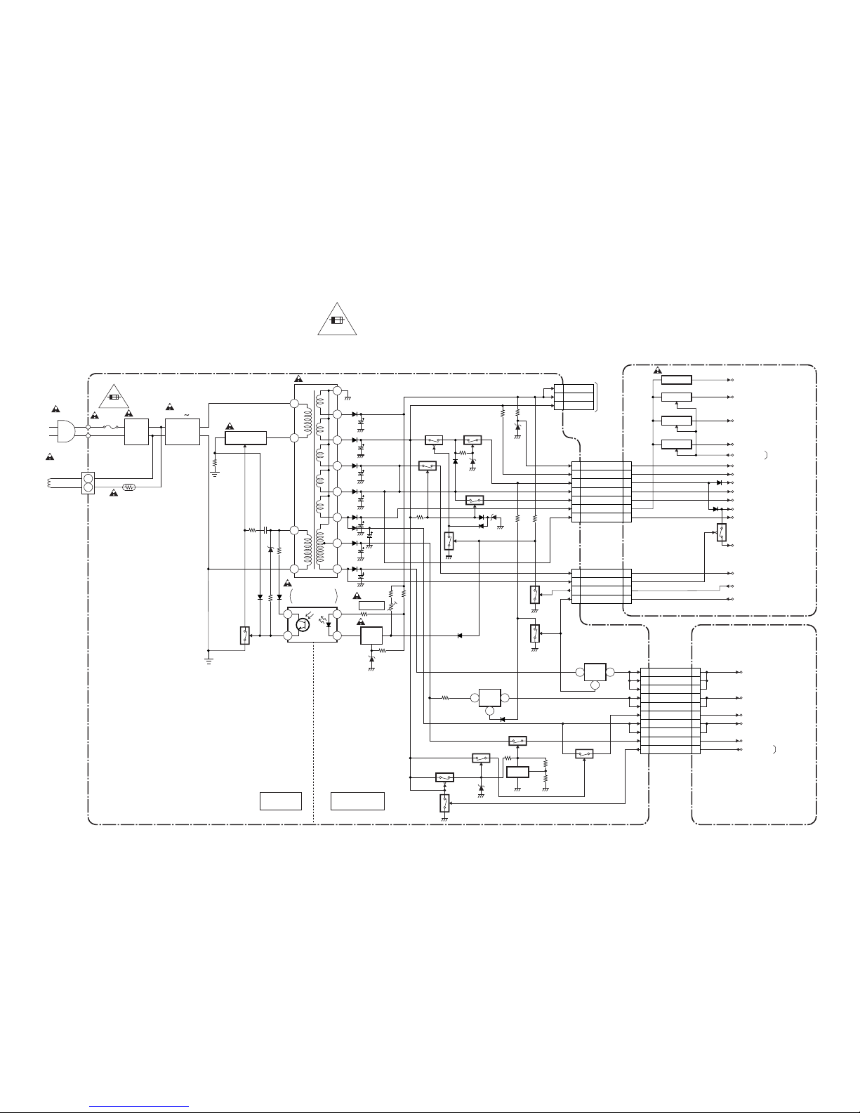
Power Supply Block Diagram
LINE
FILTER
BRIDGE
RECTIFIER
T2601
IC2601
ERROR
VOLTAGE DET
W2601
F2601
4A/125V
L2601
D2603 D2606
TD857BLP
DEGAUSSING
COIL
CN2601
PS2601
HOT
COLD
1-5-141-5-13
POWER SUPPLY/AV CBA
MAIN CBA
DVD MAIN CBA UNIT
NOTE :
The voltage for parts in hot circuit is measured using
hot GND as a common terminal.
CAUTION !
Fixed voltage power supply circuit is used in this unit.
If Main Fuse (F2601) is blown, check to see that all components in the power supply
circuit are not defective before you connect the AC plug to the AC power supply.
Otherwise it may cause some components in the power supply circuit to fail.
4A 125V
SWITCHING
Q2601
IC1602
P-DOWN
(TO PIN84 OF IC1201)
Q2604
IC2603
IC2604
VR2601
Q2602
+5V REG.
+B ADJ
5 +B
6 +B
3 DEF+B
Q1608
SW+5V
Q1611
SW+5V
Q1613
SW+5V
P-ON+5V
P-ON+5V
P-ON+5V
T+5V
P-ON+9V
P-ON+12V
AL+5V
P-ON+12V
Q1612
AL+33V
D/L+15V
P-ON+5V
+5V-CTRL
P-ON-H
(FROM PIN31 OF IC1201)
DVD-MAIN-POWER
(FROM PIN42 OF IC1201)
CN2602 TO CN502
TO
CRT/H.V.
BLOCK
CN2804 CN1803
CN2803 CN1804
CN2402 CN401
DVD-ON+3.3V
1
23
4
13 13DVD-ON+5V
16 16
DVD-MAIN-POWER
9 9P-ON-H
2 2P-ON+9V(3)
19 19AC-DOWN
19 19D/L+15V
4 4P-ON+9V(1)
10 10P-ON+12V
18 18P-ON+12V
9 9AL+33V
8 8AL+5.7V
6 6P-ON+9V(2)
3 3EV+1.5V
2 2EV+1.5V
1 1EV+1.5V
4 4EV+3.3V
5 5EV+3.3V
17 17DVD-ON+3.3V
14 14AL+9V
15 15AL+9V
19 19PWRCON
DVD-ON+5V
EV+3.3V
EV+1.5V
AL+9V
12
16
15
14
11
13
10
92
3
5
7
FEED
BACK
+3.3V
REG.
REG.
Q2606
Q2614
Q2607
Q2613
Q2609
Q2605
Q2615
Q2617
1 2
4
IC2602
+1.5V
REG.
1 2
4
Q2611
Q2610
Q2612
Q2608
FOR CONTINUED PROTECTION AGAINST RISK OF FIRE,
REPLACE ONLY WITH SAME TYPE 4 A, 125V FUSE.
CAUTION:
ATTENTION: UTILISER UN FUSIBLE DE RECHANGE DE MÊME TYPE DE 4A, 125V.
4A 125V
FROM CHROMA
BLOCK
P-ON+9V
NOTE FOR WIRE CONNECTORS:
1. PREFIX SYMBOL "CN" MEANS CONNECTOR.
(CAN DISCONNECT AND RECONNECT.)
2. PREFIX SYMBOL "CL" MEANS WIRE-SOLDER
HOLES OF THE PCB.
(WIRE IS SOLDERED DIRECTLY.)
PWRCON
FROM DVD SYSTEM
CONTROL
/SERVO BLOCK
<DVD SECTION>
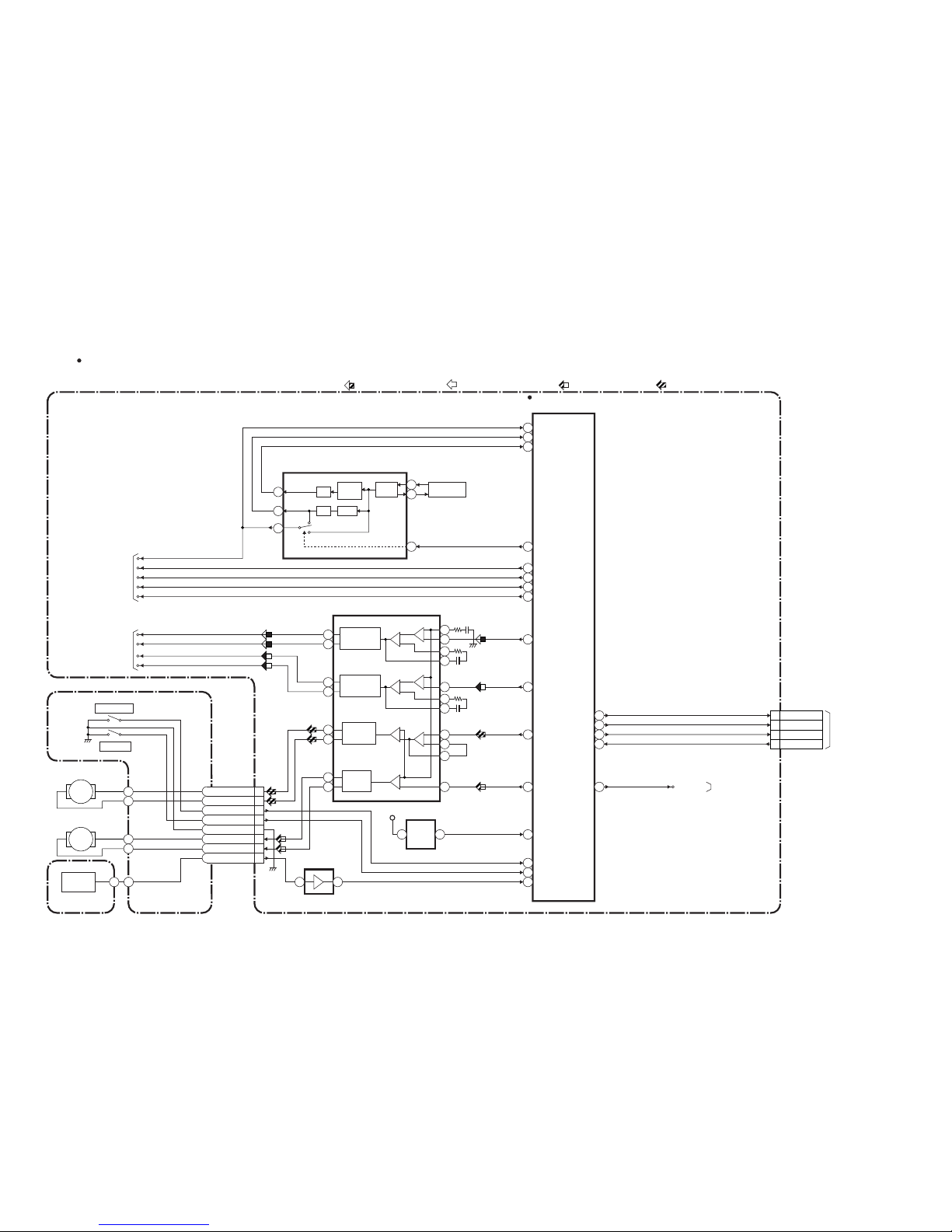
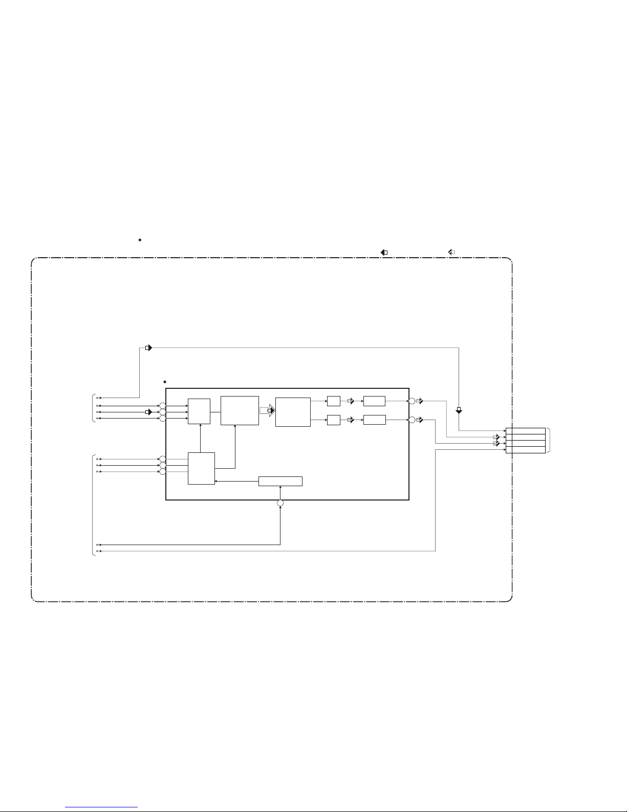
DVD System Control/Servo Block Diagram
TD857BLDS
27
7
8
3
15
10
14
26
1
2
3
4
6
23
5
17
18
12
11
14
13
15
16
25
24
54CS
55
SDATA
61
REMOTE
PWRCON PWRCON
53
SCLK
CN401
DVD MAIN CBA UNIT
DRIVE CBA
IC301
(SERVO DRIVE)
IC451
(CLOCK GENERATOR)
BLOCK DIAGRAMS < DVD Section >
IC202
(OP AMP)
12 14
CN301
FG CBA
FG
SENSOR
M
SLED
MOTOR
M
SPINDLE
MOTOR
IC101
(MICRO CONTROLLER)
+
-+
-
+
-
+
-
+
-
+
-
+
-
SLED
MOTOR
DRIVE
FOCUS
ACTUATOR
DRIVE
1/4
1/4
PLL2
X451
MULTI
PLL
X'TAL
OSC
36.864MHz
OSC
SPINDLE
MOTOR
DRIVE
TRACKING
ACTUATOR
DRIVE
EXT CLOCK
CLK33M
BE CLOCK
172
170
150
TRAY-OUT
TRAY-IN
FG-IN
97
SLD70
SPDL71
TRACKING
DRIVE
152
FOCUS DRIVE
60
66
TO DIGITAL SIGNAL
PROCESS BLOCK
FS(+)
FS(-)
TS(+)
TS(-)
TO DVD/ AUDIO
BLOCK
51
ADAC-MD
50 ADAC-MC
96 ADAC-ML
ADAC-MC
ADAC-ML
PCM-SCLK
95
A-MUTE
ADAC-MD
A-MUTE
1792FSEL
RESET68
RESET
IC461
5 4
+3.3V
TRAY-OUT
TRAY-IN
FOCUS SERVO SIGNAL TRACKING SERVO SIGNAL
SLED SERVO SIGNAL SPINDLE SERVO SIGNAL
3SP(+)
4SP(-)
5TRAY-OUT
6TRAY-IN
7GND
8SL(-)
9SL(+)
1FG-IN
18 CS
20 SDATA
21 SCLK
22
DVD-REMOTE
FROM/TO SERVO
/SYSTEM CONTROL
BLOCK
<TV/VCR SECTION>
CN2402
63
TO POWER
SUPPLY BLOCK
<TV/VCR SECTION>
1-5-161-5-15
DVD-
" " = SMD
NOTE FOR WIRE CONNECTORS:
1. PREFIX SYMBOL "CN" MEANS CONNECTOR.
(CAN DISCONNECT AND RECONNECT.)
2. PREFIX SYMBOL "CL" MEANS WIRE-SOLDER
HOLES OF THE PCB.
(WIRE IS SOLDERED DIRECTLY.)
Digital Signal Process Block Diagram
TD857BLD
C 6
D 7
A 8
B 5
F 10
E 2
DVD-LD 14
CD-LD 12
PD-MONI 13
FS(+) 18
FS(-) 19
TS(+) 20
TS(-) 17
CN201
CN201
CN201
IC201
(SW)
IC105 (LATCH)
IC102 (SDRAM) IC101 (MICRO CONTROLLER)
FS
FS(+)
CD/DVD
FS(-)
TS(+)
TS(-)
TS
PICK-UP
UNIT
DETECTOR
CD/DVD 9
Q251,Q252
CD DVD
AMP
Q253,Q254
AMP
4
1 3
6
GND(DVD-PD)
15
GND(CD-PD)
16
GND(LD)
11
FROM DVD SYSTEM
CONTROL/SERVO
BLOCK
RF
SIGNAL
PROCESS
CIRCUIT
DVD/CD
FORMATTER
AUDIO
I/F
VIDEO
I/F
NTSC/PAL
ENCODER
DMA
BCU
INST.
ROM
32BIT
CPU
DATA
ROM
INTERRUPT
CONTROLLER
WATCH DOG
TIMER
CPU
I/F
TIMER
DECODER
I/F
CPU
I/F
READ
MEMORY
DATA
ROM
DSP
DECODER
PIXEL
OPERATION
I/O
PROCESSOR
INST.
ROM
DATA
ROM
INST.
ROM
DATA
ROM
INST.
ROM
SERIAL
D/A
GENERAL
I/O
INTERRUPT
CONTROLLER
TIMER
WATCH DOG
TIMER
32BIT CPU
STREAM
I/F
EXTERNAL
MEMORY
I/F
SDRAM
ECC
UMAC
124
125
122
123
128
129
126
127
131
130
135
133
132
134
78
DEBUG
BCU
INST
CACHE
D TYPE
LATCH
DATA
CACHE
D/A
TO CHROMA
BLOCK
CN2401
158
164
Y
CN601
C
TO DVD
AUDIO
BLOCK
181
SPDIF
175
PCM-BCK
176
PCM-DATA0
174
PCM-LRCLK
EXADT (0-15), EXADR (16-19)
EXADT (0-15), EXADR (16-19)
EXADT (0-7)
EXADT (8-15)
EXADR (0-7)
EXADR (0-15)
EXADR (8-15)
SDRAM DATA(0-31)SDRAM DATA(0-31)
SDRAM ADDRESS(0-10)SDRAM ADDRESS(0-10)
2
9
~
12
19
~
210
235
~
IC104 (LATCH)
D TYPE
LATCH
2
9
~
12
19
~
2
13
184
205
247
256
~~~
2
13
31
56
74
85
~~~
IC103 (FLASH ROM)
FLASH
ROM
29
36
38
45
~
~
DVD MAIN CBA UNIT
DATA(VIDEO/AUDIO) SIGNAL DVD VIDEO SIGNAL
DATA(AUDIO) SIGNAL
FOCUS SERVO SIGNAL TRACKING SERVO SIGNAL
24
27
60
66
~~
EXADT (0-15)
EXADR (16-19)
~
1
9
16
25
48
~
1 DVD-Y
3 DVD-C
1-5-181-5-17
<TV/VCR SECTION>
" " = SMD
NOTE FOR WIRE CONNECTORS:
1. PREFIX SYMBOL "CN" MEANS CONNECTOR.
(CAN DISCONNECT AND RECONNECT.)
2. PREFIX SYMBOL "CL" MEANS WIRE-SOLDER
HOLES OF THE PCB.
(WIRE IS SOLDERED DIRECTLY.)
DVD Audio Block Diagram
TD857BLAD
IC601 (AUDIO DAC)
7
8
CN601
1
2
3
13
14
15
16
FROM
DVD SYSTEM
CONTROL
/SERVO
BLOCK
FROM
DIGITAL
SIGNAL
PROCESS
BLOCK
SERIAL
PORT
SERIAL
CONTROL
4X/8X
OVERSAMPLING
DIGITAL FILTER
/FUNCTION
CONTROLLER
ENHANCED
MULTI-LEVEL
DELTA-SIGMA
MODULATOR
DAC
LPF+AMP
L-CH
R-CH
LPF+AMP
DAC
SYSTEM CLOCK
PCM-BCK
SPDIF
PCM-DATA0
PCM-LRCLK
ADAC-MD
ADAC-MC
ADAC-ML
PCM-SCLK
DVD MAIN CBA UNIT
DATA(AUDIO) SIGNAL
A-MUTE
12 SPDIF
7 DVD-A(L)
9 DVD-A(R)
6 DVD-A-MUTE
TO AUDIO BLOCK
<TV/VCR SECTION>
CN2401
DVD AUDIO SIGNAL
1-5-201-5-19
" " = SMD
NOTE FOR WIRE CONNECTORS:
1. PREFIX SYMBOL "CN" MEANS CONNECTOR.
(CAN DISCONNECT AND RECONNECT.)
2. PREFIX SYMBOL "CL" MEANS WIRE-SOLDER
HOLES OF THE PCB.
(WIRE IS SOLDERED DIRECTLY.)
 Loading...