

Page 1
Owner’s Manual
Manuel du Propriétaire
Manual del Propietario
32MD311B/32MD301B
26MD311B/26MD301B
22MD311B
19MD311B/19MD301B
LCD TV/DVD
1-866-341-3738
Quick Use Guide Inside!
Guide d’usage Rapide Incluse!
Guía de Uso Rápido Incluida!
1-866-341-3738
Necesita ayuda
inmediata?
1-866-341-3738
English
Français Español
MODEL NUMBER SERIAL NUMBER
Page 2
2
www.magnavox.com/support today to get the very most from your purchase.
Return your Product Registration Card or register online at
Registering your model with MAGNAVOX makes you eligible for all of the valuable benefits listed below, so don't miss out. Complete and
return your Product Registration Card at once, or register online at www.magnavox.com/support to ensure:
*Product Safety Notification *Additional Benefits
By registering your product, you'll receive notification
- directly from the manufacturer - in the rare case of
a product recall or safety defect.
Know these
safetysymbols
CAUTION
RISK OF ELECTRIC SHOCK
CAUTION: TO REDUCE THE RISK OF ELECTRIC SHOCK, DO NOT
INSIDE. REFER SERVICING TO QUALIFIED SERVICE PERSONNEL.
WARNING: To reduce the risk of fire or electric shock, this apparatus should not be exposed to rain or moisture and objects filled
with liquids, such as vases, should not be placed on this apparatus.
CAUTION: To prevent electric shock, match wide blade of plug to wide slot, fully insert.
ATTENTION: Pour éviter les choc électriques, introduire la lame la plus large de la fiche dans la borne correspondante de la prise et
pousser jusqu’au fond.
Wall Mount Bracket Kit
Recommended Wall Mount Bracket Kit:
Brand: SANUS
Model #: 32MD311B / 32MD301B
26MD311B / 26MD301B SAN213b
22MD311B / 19MD311B / 19MD301B
<for 32 inches, 26 inches only>
Do NOT use screws packed
with Wall Mount Bracket Kit.
Recommended Screw dimension when purchased:
32MD311B / 32MD301B M4 x 0.787” (20mm)
26MD311B / 26MD301B M4 x 0.629” (16mm)
22MD311B / 19MD311B / 19MD301B M4 x 0.472” (12mm)
• The recommended Wall Mount Bracket Kit (sold
separately) allows the mounting of the TV on the wall.
• For detailed information on installing the wall mount,
refer to the Wall Mount Instruction Book.
• Funai is not responsible for any damage to the product
or injury to yourself or other s if you elect to install the
TV Wall Mount Bracket or mount the TV onto the
Bracket on your own.
• The Wall Mount Bracket must be installed by experts.
DO NOT OPEN
REMOVE COVER (OR BACK). NO USER-SERVICEABLE PARTS
Visit our World Wide Web Site at www.magnavox.com/support
San25b
San10B
+ Washer 0.078”(T2mm)
Registering your product guarantees that you'll
receive all of the privileges to which you're
entitled, including special money-saving offers.
This “bolt of lightning” indicates uninsulated material
within your unit may cause an electrical shock.For the
safety of everyone in your household, please do not
remove product covering.
The “exclamation point” calls attention to features for
which you should read the enclosed literature closely to
prevent operating and maintenance problems.
Funai not liable for these types of accidents
or injury noted below.
• Install the Wall Mount Bracket on a sturdy vertical wall.
• If installed onto a ceiling or slanted wall, the TV and Wall
Mount Bracket may fall which could result in a severe injury.
• Do not use screws that are longer or shor ter than their
specifi ed length. If screws too long are used this may cause
mechanical or electrical damage inside the TV set. If screws
too short are used this may cause the TV set to fall.
• Do not fasten the screws by excessive force; this may
damage the product or cause the product to fall, leading to
an injury.
• For safety reasons use 2 people to mount the TV onto a
Wall Mounting Bracket.
• Do not mount the TV onto the Wall Mounting Bracket
while your TV is plugged in or turned on. It may result in an
electrical shock injury.
When installing the unit on the wall, allow this much space.
Top: 11.8 inches (30cm)
Left and right side: 5.9 inches (15cm)
Bottom: 3.9 inches (10cm)
Page 3
IMPORTANT SAFETY INSTRUCTIONS
Read before operating equipment
1. Read these instr uctions.
2. Keep these instr uctions.
3. Heed all warnings.
4. Follow all instructions.
5. Do not use this apparatus near water.
6. Clean only with a dr y cloth.
7. Do not block any of the ventilation openings.
Install in accordance with the manufacturer’s instructions.
8. Do not install near any heat sources such as radiators, heat
registers, stoves, or other apparatus (including amplifiers)
that produce heat.
9. Do not defeat the safety purpose of the polarized or
grounding-type plug. A polarized plug has two blades with
one wider than the other. A grounding type plug has two
blades and third grounding prong. The wide blade or third
prong are provided for your safety. When the provided
plug does not fit into your outlet, consult an electrician for
replacement of the obsolete outlet.
10. Protect the power cord from being walked on or pinched
particularly at plugs, convenience receptacles, and the point
where they exit from the apparatus.
11. Only use attachments/accessories specified by the
manufacturer.
12.
Use only with a cart, stand, tripod, bracket, or table
specified by the manufacturer, or sold with the apparatus. When a cart is used, use caution when moving the
cart/apparatus combination to avoid injury from tip-over.
13. Unplug this apparatus during lightning storms or when unused for long periods of time.
14. Refer all servicing to qualified ser vice personnel. Servicing is
required when the apparatus has been damaged in any way,
such as power-supply cord or plug is damaged, liquid has
been spilled or objects have fallen into apparatus, the apparatus has been exposed to rain or moisture, does not operate
normally, or has been dropped.
15. Damage Requiring Service - The appliance should be
serviced by qualified ser vice personnel when:
A. The power supply cord or the plug has been damaged;
B. Objects have fallen, or liquid has been spilled into the
appliance;
C. The appliance has been exposed to rain
D. The appliance does not appear to operate normally or
exhibits a marked change in performance;
E. The appliance has been dropped, or the enclosure damaged.
16. Tilt/Stability - All televisions must comply with recommended
international global safety standards for tilt
and stability properties of its cabinet design.
• Do not compromise these design standards by applying
excessive pull force to the front, or top, of the cabinet
which could ultimately overturn the product.
• Also, do not endanger yourself, or children, by placing
electronic equipment/toys on the top of the cabinet. Such
items could unsuspectingly fall from the top of the set and
cause product damage and/or personal injury.
17. Wall or Ceiling Mounting - The appliance should be
mounted to a wall or ceiling only as recommended by the
manufacturer.
18. Power Lines - An outdoor antenna should be located
away from power lines.
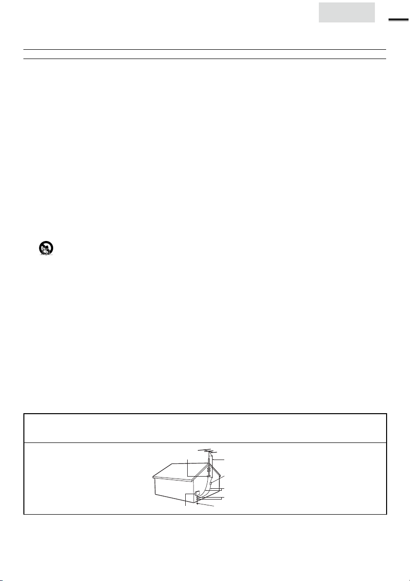
19. Outdoor Antenna Grounding - If an outside antenna
is connected to the receiver, be sure the antenna system is
grounded so as to provide some protection against voltage
surges and built up static charges.
Section 810 of the National Electric Code, ANSI/NFPA
No. 70-1984, provides information with respect to proper
grounding of the mast and supporting structure, grounding of the lead-in wire to an antenna discharge unit, size of
grounding connectors, location of antenna-discharge unit,
connection to grounding electrodes, and requirements for
the grounding electrode. See Figure below.
20. Object and Liquid Entry - Care should be taken so
that objects do not fall and liquids are not spilled into the
enclosure through openings.
21. Battery Usage CAUTION - To prevent battery
leakage that may result in bodily injury, property damage ,
or damage to the unit:
• Install all batteries cor rectly, with + and - aligned as
marked on the unit.
• Do not mix batteries (old and new or carbon and
alkaline, etc.).
• Remove batteries when the unit is not used for a long
time.
English
3
Note to the CATV system installer : This reminder is provided to call the CATV system installer’s attention to Article
820-40 of the NEC that provides guidelines for proper grounding and, in particular, specifies that the cable ground shall
be connected to the grounding system of the building, as close to the point of cable entry as practical.
Example of Antenna Grounding as
per NEC - National Electric Code
GROUND CLAMP
ELECTRIC SERVICE EQUIPMENT
ANTENNA LEAD IN WIRE
ANTENNA DISCHARGE UNIT (NEC SECTION 810-20)
GROUNDING CONDUCTORS (NEC SECTION 810-21)
GROUND CLAMPS
POWER SERVICE GROUNDING ELECTRODE SYSTEM (NEC ART 250, PART H)
Page 4
4
FCC WARNING
This apparatus may generate or use radio frequency energy. Changes or modifications to this apparatus may cause harmful interference
unless the modifications are expressly approved in the manual. The user could lose the authority to operate this apparatus if an
unauthorized change or modification is made.
RADIO-TV INTERFERENCE
This apparatus has been tested and found to comply with the limits for a Class B digital device, pursuant to Part 15 of the FCC Rules.
These limits are designed to provide reasonable protection against harmful interference in a residential installation. This apparatus
generates, uses, and can radiate radio frequency energy and, if not installed and used in accordance with the instructions, may cause
harmful interference to radio communications. However, there is no guarantee that interference will not occur in a particular installation.
If this apparatus does cause harmful interference to radio or television reception, which can be determined by turning the apparatus off
and on, the user is encouraged to try to correct the interference by one or more of the following measures:
1) Reorient or relocate the receiving antenna.
2) Increase the separation between the apparatus and receiver.
3) Connect the apparatus into an outlet on a circuit different from that to which the receiver is connected.
4) Consult the dealer or an experienced radio/TV technician for help.
DECLARATION OF CONFORMITY
Trade Name: MAGNAVOX Responsible Party: FUNAI CORPORATION, Inc.
This Class B digital apparatus complies with Canadian ICES-003. Standard Television Receiving Apparatus, Canada BETS-7 / NTMR-7
CAUTION :
WARNING :
Disconnect the mains plug to shut off when find trouble or not in use. The mains plug shall remain readily operable.
This apparatus should not be placed in a built-in installation such as a bookcase or rack unless proper ventilation is provided.
Make sure to leave a space of 4 inches (10cm) or more around this apparatus.
WARNING:
Do not place the unit on the furniture that is capable of being tilted by a child and an adult leaning, pulling, standing or
climbing on it. A falling unit can cause serious injury or even death.
LASER SAFETY
This apparatus is classified as a CLASS 1 LASER PRODUCT. This apparatus employs a
laser. Only a qualified service person should remove the cover or attempt to service this
apparatus, due to possible eye injury.
CAUTION: Use of controls or adjustments or performance of procedures other than
IMPORTANT COPYRIGHT INFORMATION
Unauthorized copying, broadcasting, public performance and lending of discs are prohibited. This item incorporates copy
protection technology that is protected by U.S. patents and other intellectual property rights of Rovi Corporation.
Reverse engineering and disassembly are prohibited.
Like all LCD products, this set contains a lamp with Mercury, please dispose of according to all Local, State and
32MD311B / 32MD301B
Model:
26MD311B / 26MD301B
22MD311B / 19MD311B / 19MD301B
Telephone Number:
Address: 19900 Van Ness Avenue, Torrance, CA 90501 U.S.A.
1-866-341-3738
Danger of explosion if battery is incorrectly replaced. Replace only with the same or equivalent type.
Batteries (battery pack or battery installed) shall not be exposed to excessive heat such as sunshine, fire or the like.
To prevent injury, this apparatus must be securely attached to the wall in accordance with the instructions.
those specified herein may result in hazardous radiation exposure.
Federal laws. For the disposal or recycling information, contact:
www.mygreenelectronics.com or www.eiae.org
• The American Academy of Pediatrics discourages television
viewing for children younger than two years of age.
NOTE ABOUT RECYCLING
• This unit’s packaging materials are recyclable and
can be reused. Please dispose of any materials in
accordance with your local recycling regulations.
• Batteries should never be thrown away or
incinerated but disposed of in accordance with your
local regulations concerning chemical wastes.
• For product recycling information, please visit - www.magnavox.com
WHEN CARRYING THIS UNIT
• At least 2 people are required when
carrying this unit.
• Make sure to hold the upper and bottom
frames of the unit fi rmly as illustrated.
TO AVOID THE HAZARDS OF
ELECTRICAL SHOCK AND FIRE
• Do not handle the AC power cord with wet hands.
• Do not pull on the AC power cord when disconnecting it from an
AC outlet. Grasp it by the plug.
• Do not put your fi ngers or objects into the unit.
LOCATION AND HANDLING
• Do not install the unit in direct sunlight or in a place subject to dust
or strong vibration.
• Avoid a place with drastic temperature changes.
• Install the unit in a horizontal and stable position. Do not place
anything directly on top or bottom of the unit. Depending on your
external devices, noise or disturbance of the picture and / or sound
may be generated if the unit is placed too close to them. In this case,
please ensure enough space between the external devices and the
unit.
• Depending on the environment, the temperature of this unit may
increase slightly. This is not a malfunction.
• Be sure to unplug the AC power cord from the AC outlet before
moving or carrying the unit.
DEW CONDENSATION WARNING
• Dew condensation may form inside the unit in the following
conditions. If so, do not use this unit at least for a few hours until its
inside gets dry.
- The unit is moved from a cold place to a warm place.
- Under conditions of high humidity.
- After heating a cold room.
Page 5

Child Safety
English
5
Page 6
6
INTRODUCTION
Contents
Important Safety Instructions 3
Child Safety 5
INTRODUCTION
Trademark Information 6
Features 7
Supplied Accessories 8
Symbols Used in this Manual 8
Attaching the Base 8
Mounting the Unit on Your Furniture 9
Tilt Stand <22MD311B / 19MD311B / 19MD301B only> 9
Installing the Batteries 9
Control Panel 10
Terminals 10
Remote Control Function 12
PREPARATION
Antenna Connection 13
Connection to Cable Receiver or Satellite Box 14
Plug In the AC Power Cord 14
Initial Setup 15
WATCHING TV
Sleep Timer 16
Switching Each Input Mode 16
Freeze Mode 16
Channel Selection 16
TV Screen Display Mode 17
Sound Functions 17
TV Screen Information 18
USING FUNCTIONS
Picture 20
Sound 20
Channel 21
Features 22
Language 27
DVD 27
Language Code List 29
OPERATING DVD
Playable Media 30
Unplayable Media 30
Playback 31
Disc Menu 31
Resume Playback 31
Paused and Step-by-step Playback 31
Fast Forward / Fast Reverse 31
Slow Forward / Slow Reverse 32
Zoom 32
Search Functions 32
Repeat Playback 33
Repeat A-B Playback 33
Random Playback 33
Programmed Playback 33
On-screen Display 34
Special Settings 34
CONNECTING DEVICES
External Device Connection 36
Cable Management
<32MD311B / 32MD301B / 26MD311B / 26MD301B only> 39
USEFUL TIPS
Troubleshooting Guide 40
FAQ 42
INFORMATION
Glossary 43
Maintenance 43
General Specifi cations 44
Other Specifi cations 44
Limited Warranty 47
Trademark Information
HDMI, the HDMI Logo, and High-Defi nition Multimedia Interface are
trademarks or registered trademar ks of HDMI Licensing LLC in the
United States and other countries.
Manufactured under license from Dolby Laboratories. Dolby and the
double-D symbol are trademarks of Dolby Laboratories.
ENERGY STAR® is a joint program of the U.S. Environmental
Protection Agency and the U.S. Department of Energy helping us all
save money and protect the environment through energy effi cient
products and practices.
Consumer Notice:
This TV has been set to maximize energy effi ciency while delivering
the best possible picture using the factory installed home mode
settings. Changing or enabling other features in this TV (e.g. brightened
backlighting) will possibly increase energy consumption beyond the
original ENERGY STAR® qualifi ed limits.
is a trademark of DVD Format/Logo Licensing Corporation.
© 2011 Funai Electric Co., Ltd.
All rights reserved . No par t of this manual may be reproduced, copied,
transmitted, disseminated, transcribed, downloaded or stored in any
storage medium, in any form or for any purpose without the express prior
written consent of Funai. Furthermore, any unauthorized commercial
distribution of this manual or any revision hereto is strictly prohibited.
Information in this document is subject to change withou t notice. Fu nai
reser ves the right to change the content he rein withou t the obligation to
notify any person or organization of such changes.
with the design is a registered trade mark of Funai Electric
Co., Ltd . and may not be used in any way without the express wri tten
consent of Funai. All other trademar ks used herein remain the exclusive
property of t heir res pective owners. Nothing contained in this manual
should be construed as gr anting, by implication or otherwise, any license
or right to use any of the trademarks displayed herein. Misuse of any
trademarks or any other content in this manual is strictly prohibited.
Funai shall aggr essively enforce its intellectual proper ty r ights to t he
fulles t exte nt of the law.
MAGNAVOX is a registered trademark of Philips Elec tronics North
America Corporation and is used by Funai Electric Co. Ltd. and Funai
Corporation, Inc. under license from Philips Electronics North America.
Page 7

Features
English
7
INTRODUCTION
TV
• DTV / TV / CATV
You can use your remote control to select channels which are
broadcast in digital format and conventional analog format. Also,
cable subscribers can access their cable TV channels.
• Information Display (ATSC only)
You can display the title, contents and other information of the
current DTV program on the TV screen.
• Autoprogram
This unit automatically scans and memorizes channels available in
your area, eliminating diffi cult setup procedures.
• Child Lock
This feature allows you to block children’s access to inappropriate
programs.
• Closed Caption Decoder
Built-in closed caption decoder displays text for closed caption
supported programs.
• MTS / SAP Tuner
Audio can be selected from the remote control.
• Auto Standby
If there is no input signal and no operation for 15 minutes, the
unit will go into standby mode automatically.
• Sleep Timer
You can set the unit to go into standby mode after a specifi c
amount of time.
• Choices for On-screen Language
Select your on-screen language:
English, Spanish or French.
• Stereo Sound Function
• PLL Frequency Synthesized Tuning
Provides free and easy channel selection and lets you tune
directly to any channel using the number and decimal point “•”
buttons on the remote control.
• Various Adjustment for Picture and Sound
Customizes image quality suitable for your room and sets your
sound preference.
• fun-Link via HDMI Link (HDMI Cable not Included)
fun-Link allows your other HDMI link devices to be controlled by
the HDMI cable connected to your TV.
• HDMI Input
• Component Video Input
• S-Video Input
• AV Input
• Digital Audio Output
<32MD311B / 32MD301B / 26MD311B / 26MD301B only>
• HDMI-DVI Input
When using HDMI 1 Input, you can enjoy this unit as a PC
monitor if your PC has a DVI output terminal.
• Analog Audio output
<22MD311B / 19MD311B / 19MD301B only>
• HDMI-DVI Input
If your video device has DVI output jack, use an HDMI-DVI
conversion cable to connect the unit.
• PC Input
• Headphone Audio Output
DVD
• Dolby Digital Sound
Enjoy Dolby Digital multi-channel surround sound when you
connect the unit to your Dolby Digital decoder.
• Still / Fast / Slow / Step Playback
Various playback modes are available including still pictures, fast
forward/reverse, slow motion and step frames.
• DVD Menus in a Desired Language
You can display DVD menus in a desired language, if available on
a DVD-video.
• Auto standby
If there is no operation for 20 minutes, the unit will go into
standby mode automatically.
• Parental Lock
Block the viewing of a DVD-video unsuitable for children.
• Resume Playback
Lets you resume playback from the point at which playback was
stopped.
• Bit Rate Indication
• DRC (dynamic range control)
You can control the range of sound volume.
Accessing from MODE button
During playback
• Subtitles in a Desired Language
You can select a desired language for displaying subtitle, if that
language is available on a DVD-video.
• Selecting a Camera Angle
You can select the desired camera angle, if a DVD contains
sequences recorded from different angles.
• Zoom
Allows you to enlarge the size of picture image.
• Black Level Adjustment
• Virtual Surround
• Search
chapter search / title search / track search / time search
• Marker
The part on the disc designated by user can be called back.
• Repeat
chapter / title / track / all / A-B
Accessing from MODE button
In stop mode
• Program Playback for audio CD
You can program the order of tracks to play them back in
designated order.
• Random Playback for audio CD
This unit can shuffl e the order of tracks to play them back in
randomly.
Accessing from AUDIO button
During playback
• Choices for Audio Language and Stereo Sound Function
Select your desired languages or stereo sound function when
different options are available on your disc.
PREPARATION WATCHING TV
USING FUNCTIONS OPERATING DVD
CONNECTING DEVICES
INFORMATION USEFUL TIPS
Page 8
8
AAA
AAA
FRONT
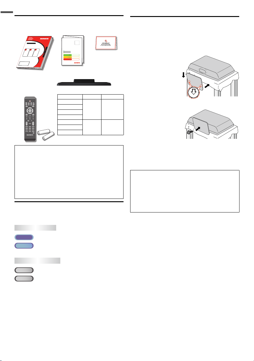
Supplied Accessories
Owner’s Manual Quick Start Guide
If you have any questions, please visit our website at
www.
magnavox.com/support
Quick
Start
EN
Installation
FR
Installation
ES
Instalación
Best
Better
Good
Remote Control
TV base and screws
(NF801UD)
Batteries
(AAA, 1.5V x 2)
Screws packed with this unit:
Model Quantity Size
32MD311B
32MD301B
26MD311B
26MD301B
22MD311B
19MD301B
Note
• If you lose the screws, please purchase the above-mentioned
Phillips head screws at your local store.
• If you need to replace these accessories, please refer to the part
name and No. with the illustrations and call our toll free customer
support line found on the cover of this manual.
When using a universal remote control to operate this unit.
• Make sure the component code on your universal remote control
is set to our brand. Refer to the manual accompanying your
remote control for more details.
• We do not guarantee 100% interoperability with all universal
remote controls.
Registration card
4 M4 x 20
3 M4 x 1219MD311B
Symbols Used in this Manual
The following is the description for the symbols used in this
manual. Description refers to:
TV FUNCTIONS
ATS C
: Digital TV operation
NTSC
: Analog / Cable TV operation
• If neither symbol appears, the operation is applicable to both.
DVD FUNCTIONS
DVD
: Playback of DVD-video
CD
: Playback of audio CD
• If neither symbol appears under the function heading, operation is
applicable to both.
Attaching the Base
You must attach the base to the unit to have it as a table top
unit. Be sure the front and rear of the base match the proper
direction. At least 2 people are required for these steps.
1 Spread a thick and soft cloth over a table as shown at step 2.
Place the main unit face down onto it. Make sure not to
damage the screen.
2 Inser t 2 hooks under the
bottom of the main unit
into base holes (shown by
arrow ➀), then move the
base in the direction as
shown by arrow ➁ until it
stops and the screw holes
are aligned. Make sure not
to put the AC power cord between the base and the unit.
➁
➀
3 Drive Phillips head screws
into the threaded holes
at the bottom of the base
until they are tight.
To remove the base from this unit
• Unscrew the Phillips head screws in step 3.
After the screws are removed, move the base in the opposite direction
as shown by arrow in step 2, then pull the base up toward the rear of
the unit. Be careful not to drop the base when you remove it.
Note
• When attaching the base, ensure that all screws are tightly fastened. If
the base is not properly attached, it could cause the unit to fall, resulting
in injuries as well as damage to the unit.
• Make sure to use a table which can support the weight of this unit and
is larger than this unit.
• Make sure the table is in a stable location.
• When attaching the base, ensure that FRONT ↑ written on the base is
upward. If it’s not upward, the 2 hooks don’t fi t in the base.
Page 9
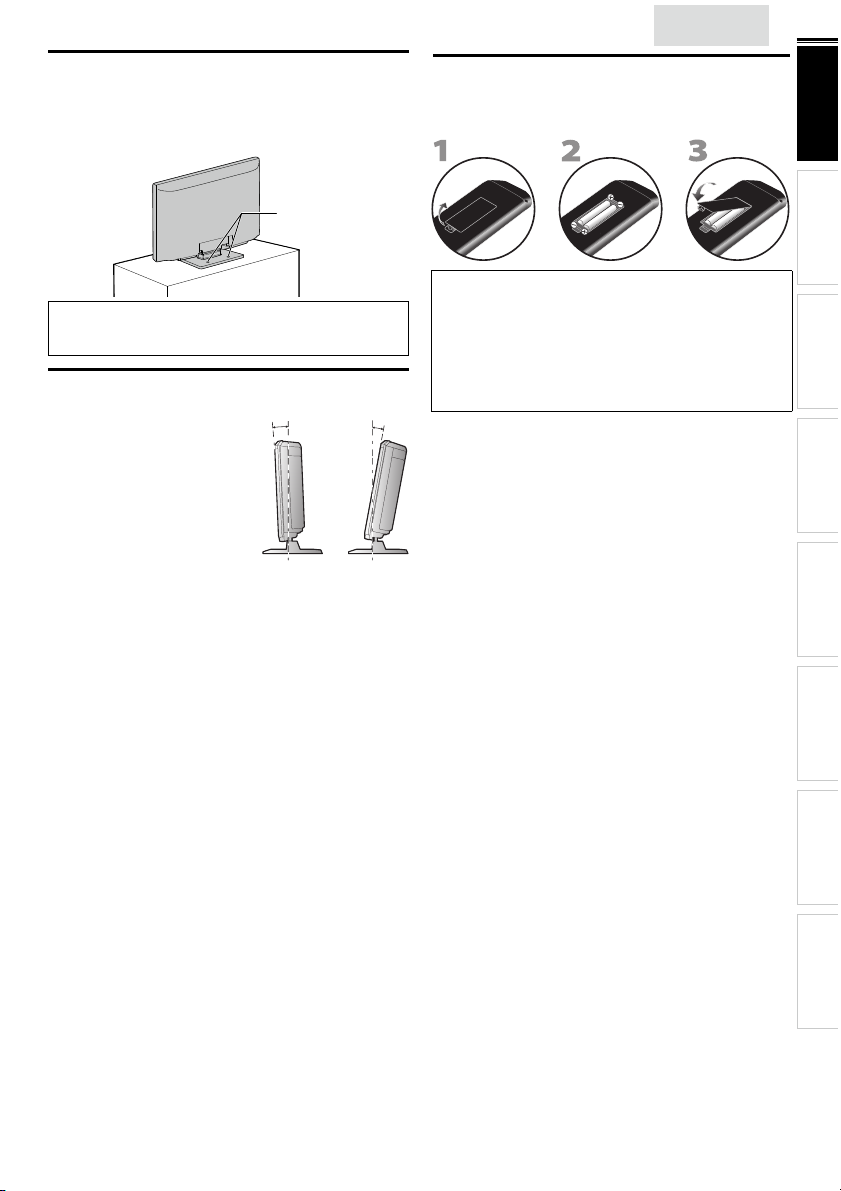
Mounting the Unit on Your Furniture
screw holes
rear of the unit
AAAAAAAAA
AAA
AAAAAA
Screw this unit on your furniture tightly using wood screws
(not supplied) in the 2 holes at the back of the base as shown.
• Recommended screw dimension : 0.201 x 0.788 inches (5.1 x 20 mm)
screw holes
English
Installing the Batteries
Install the batteries (AAA, 1.5V x 2) matching the polarity
indicated inside battery compar tment of the remote control.
9
INTRODUCTION
PREPARATION WATCHING TV
rear of the unit
Note
• When you remove this unit make sure to unscrew the wood
screws from your Wood Stand, Furniture and other wood item.
Tilt Stand <22MD311B / 19MD311B / 19MD301B only>
You can adjust the stand to change
the angle of the unit (-2.5° to 10°).
-2.5°
10°
Battery Precautions:
• Be sure to follow the correct polarity as indicated in the batter y
compartment. Reversed batteries may cause damage to the device.
• Do not mix different types of batteries together (e.g. Alkaline and
Carbon-Zinc, or rechargeable batteries like ni-cad, ni-mh, etc) or old
batteries with fresh ones.
• If the device is not to be used for a long period of time, remove the
batteries to prevent damage or injury from possible batter y leakage.
• Do not try to recharge batteries; they can overheat and rupture.
USING FUNCTIONS OPERATING DVD
CONNECTING DEVICES
INFORMATION USEFUL TIPS
Page 10

10
Control Panel
MD311B series
32”
MENU
−VOLUME
+
1 2 3 4 5 6 7
26”/22”/19”
−VOLUME
+
1 2 3 4 5 6 7
MENU
−CHANNEL
−CHANNEL
+
DVD
+
32”
DVD
8 9 10 11
POWER
POWER
1 VOLUME + / −
Press to adjust the volume or move right (+) / left (−)
through the main menu items.
2 MENU
3 CHANNEL + / −
Press to select channels or move up (+) / down (−)
through the main menu items.
4 A (eject)
5 C (stop)
6 B (play)
POWER
7
Press to turn the unit on and go into standby mode.
To completely turn off the unit, you must unplug the AC
power cord.
8 DVD indicator
Lights up orange when a disc is inserted.
8
9 STAND BY indicator
9
10
10
11
11
Lights up red when the unit goes into standby mode.
10 POWER ON indicator
Lights up green when power is on.
11 Infrared sensor window
Receives infrared rays transmitted from the remote
control.
➠
➠
➠
➠
➠
➠
➠
p. 17
p. 19
p. 16
p. 31
p. 31
p. 31
p. 15
MD301B series
32”
MENU
−VOLUME
+
−CHANNEL
+
1 2 3 4 5 6 7
26”/19”
STAND BY POWER ON
−CHANNEL
DVD
+
MENU
−VOLUME
+
1 2 3 4 5 6 7
32”
STAND BYPOWER ON
DVD
8 9 10 11
POWER
POWER
8
9
9
10
10
11
11
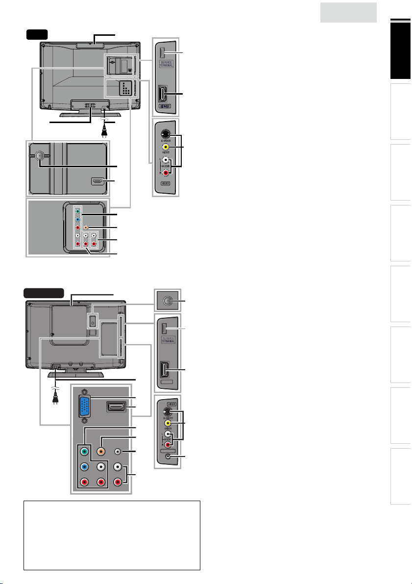
Terminals
32”
13
12
*
22
14
15
16
17
DVI
ANALOG
AUDIO
18
19
20
21
Page 11
26”
HDMI 2
HEAD PHONE
HDMI 2
HEAD PHONE
16
14
15
21
22
17
20
19
18
22”/19”
16
16
17
HDMI 2
HDMI 2
18
19
19
20
20
21
21
HEAD PHONE
HEAD PHONE
22
22
23
23
Note for service terminal
service terminal (service use only)
*
• Use this terminal only when a software update is necessary.
• User should not connect any devices to the service terminal such
as digital camera, keyboard, mouse, etc. (because these will not
work).
• The software update is, in most cases, handled by an authorized
service person or in some circumstances the user may be asked
to do the software update themselves.
<32MD311B / 32MD301B / 26MD311B / 26MD301B>
Side Panel
*
12 HDMI 2 Input jack
➠
13 S-Video / Composite Video / Audio (L/R) Input jacks
for VIDEO
Rear Panel
12
14 Disc loading slot
15 AC power cord
16 Cable management
➠
➠
➠
➠
17 Component Video and Audio (L/R) Input jacks
13
➠
18 Analog Audio (L/R) Output jacks
➠
19 Analog Audio (L/R) Input jacks for HDMI 1
Audio cable connection from a DVI device.
When you connect your PC that has a DVI terminal,
use a stereo mini plug conversion cable as well.
(For HDMI 1 Input jack only)
➠
20 Digital Audio Output jack ➠ p. 38
21 Antenna Input jack
22 HDMI 1 / HDMI-DVI Input jack
HDMI connection for HDMI or DVI device.
When you connect your PC that has a DVI terminal,
you can enjoy this unit as a PC monitor.
<22MD311B / 19MD311B / 19MD301B>
15
15
Side Panel
12 HDMI 2 Input jack
13 S-Video / Composite Video / Audio (L/R) Input jacks
*
*
for VIDEO
➠
➠
➠
➠
14 Headphone Audio Output jack
Headphone connection for personal listening.
12
12
Rear Panel
15 Antenna Input jack ➠ p. 13
16 Disc loading slot
17 AC power cord
18 PC (VGA) Input jack
13
13
19 HDMI 1 / HDMI-DVI Input jack
➠
➠
➠
➠
20 Component Video and Audio (L/R) Input jacks
14
14
21 Digital Audio Output jack
➠
➠
22 Analog Audio (L/R) Input jack for PC connection
Mini-plug audio cable connection from PC.
➠
23 Analog Audio (L/R) Input jacks for HDMI 1
Audio cable connection from a DVI device.
(For HDMI 1 Input jack only)
➠
English
p. 14, 36
p. 37, 38
p. 31
p. 14
p. 39
p. 14, 37
p. 39
p. 36, 39
p. 13
p. 14, 36, 39
p. 14, 36
p. 37, 38
p. 31
p. 14
p. 39
p. 14, 36
p. 14, 37
p. 38
p. 39
p. 36
11
INTRODUCTION
PREPARATION WATCHING TV
USING FUNCTIONS OPERATING DVD
CONNECTING DEVICES
INFORMATION USEFUL TIPS
Page 12
12
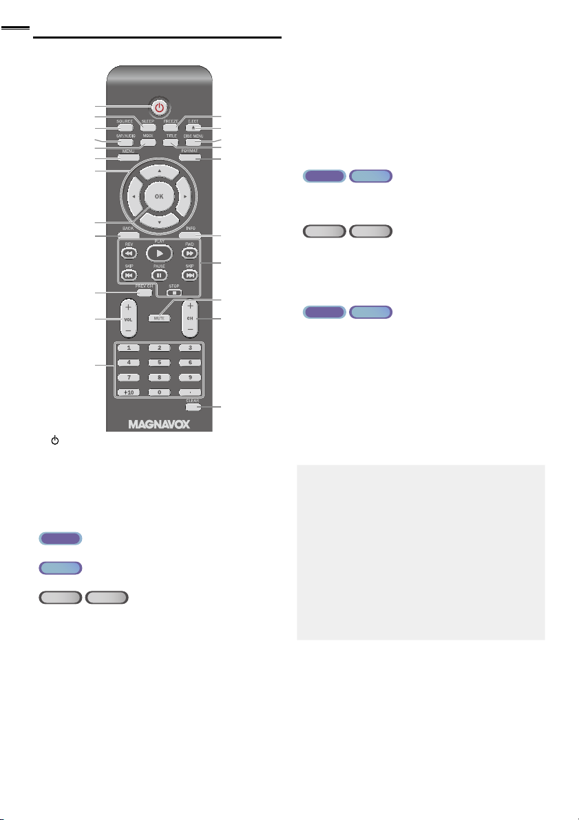
Remote Control Function
1
2
2
3
4
5
6
7
8
9
10
11
12
1 (power)
Press to turn the unit on and go into standby mode.
To completely turn off the unit, you must unplug the AC
power cord.
2 SLEEP
➠
3 SOURCE
4 SAP / AUDIO
ATS C
• Press to select the audio language.
NTSC
• Press to select the audio mode.
DVD
• Press to select the audio language (DVD), or sound
5 MODE
• Press to arrange the playing order or playback
• Press to set the black level (DVD) and the virtual
• Press to change the camera angle to see the sequence
• Press to search chapter, title (DVD), track (CD) or time.
• Press to set the marker.
• Press to repeat playback chapter, title (DVD), track, disc
• Press to magnify the par t of picture (2x and 4x : DVD).
• Press to select the subtitles on a disc (DVD).
CD
mode (CD).
➠
randomly (CD).
surround on or off.
being played back from different angle (DVD).
(CD) repeatedly or between designated point A and B.
➠
➠
➠
p. 15
p. 16
p. 16
p. 17
p. 7
13
14
15
16
17
18
19
20
21
22
6 MENU
➠
7 ▲/▼/◄/►(cursor)
8 OK
9 B ACK
10 PREV CH
Press to return to the previously viewed channel.
11 VOL + / −
➠
12 Number buttons
(dot)
directly.
NTSC
CD
ATS C
• Press to select channels.
•
• Press to shift the subchannel from the main channel.
DVD
• Press to select chapter, title (DVD), or track (CD)
➠
➠
➠
➠
➠
p. 19
p. 15
p. 15
p. 18
p. 16
p. 17
p. 16
+10 button
• Press to select 10 or higher number of chapters.
13 FREEZE ➠ p. 16
ATS C
• Press to pause screen image.
14 EJECT A
Press to eject the disc.
NTSC
p. 31
➠
15 DISC MENU ➠ p. 31
Press to display the menu on a disc.
16 TITLE ➠ p. 31
Press to display the title menu (DVD).
17 FORMAT ➠ p. 17
Press to select aspect ratio available for the TV screen.
18 INFO ➠ p. 18, 34
19 REV E / FWD D
Press to begin slow forward or slow reverse playback
during the pause mode (DVD) and search backward or
forward through a disc.
PLAY B
Press to begin the disc playback.
➠
➠
p. 31
p. 31
SKIP H / SKIP G ➠ p. 32
Press to skip backward or forward chapters, titles (DVD)
or tracks (CD) of the disc.
PAUSE F
Press to pause the disc playback.
STOP C
Press to stop the disc playback.
➠
➠
p. 31
p. 31
20 MUTE ➠ p. 17
21 CH + / −
22 CLEAR
• Press to clear the numbers entered incorrectly.
• Press to cancel the point A for A-B repeat.
• Press to remove the track number in program input
(CD).
➠
➠
p. 16
p. 32, 33
Page 13
PREPARATION
VHF / UHF
analog
or
DTV antenna
cable TV signal
RF coaxial cable
VHF / UHF
analog
or
DTV antenna
RF coaxial cable
RF coaxial cable
cable TV signal
No supplied cables are used with these connections:
• Please purchase the necessary cables at your local store.
Before you connect:
Be sure your antenna or other device is connected properly
before plugging in the AC power cord.
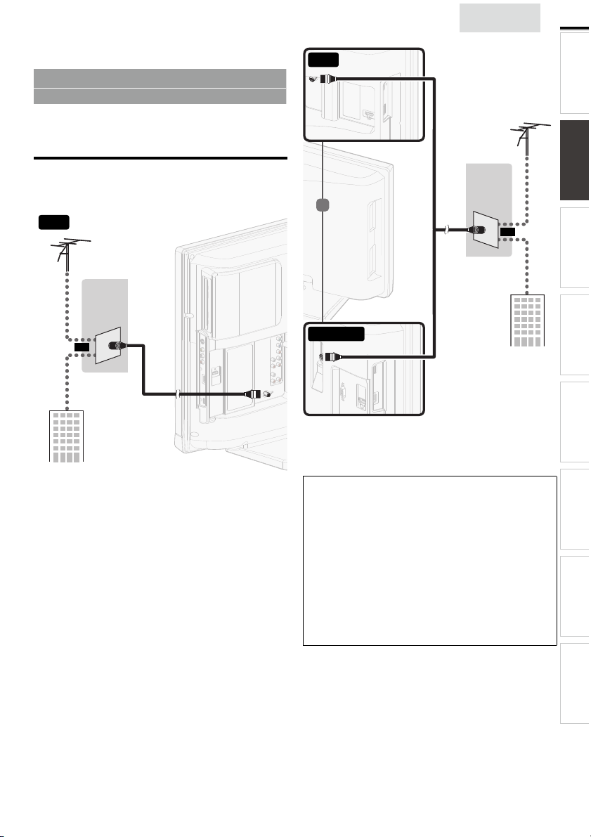
Antenna Connection
Connect the RF coaxial cable on your home outlet to the
antenna input jack of this unit.
32”
VHF / UHF
analog
or
DTV antenna
26”
RF coaxial cable
English
VHF / UHF
analog
or
DTV antenna
or
13
INTRODUCTION PREPARATION
WATCHING TV
USING FUNCTIONS OPERATING DVD
or
cable TV signal
RF coaxial cable
22”/19”
cable TV signal
RF coaxial cable
Once connections are completed, turn on the unit and begin
initial setup. Channel scanning is necessary for the unit to
memorize all available channels in your area. [Initial Setup]
p. 15
➠
Note
• If you have any question about the DTV’s antenna, visit
www.antennaweb.org for fur ther information.
• Depending on your antenna system, you may need different types
of combiners (mixers) or separator s (splitters) for HD TV signal
the minimum RF bandpass on these devices is 2,000MHz or 2GHz.
• For your safety and to avoid damage to this unit, please unplug the
RF coaxial cable from the antenna input jack before moving the
unit.
• If you did use an antenna to receive analog TV, it should also
work for DTV reception. Outdoor or attic antennas will be more
effective than a set top or inside antenna.
• To switch your reception source easily between antenna and cable,
install an antenna selector.
• If you are not receiving a signal from your cable service, contact the
Cable provider.
CONNECTING DEVICES
INFORMATION USEFUL TIPS
Page 14

14
(red)
(blue)
(green)
cable receiver /
satellite box
cable TV signal
including PPV
component video cables
(red / blue / green) and audio cables
RF coaxial cable
HDMI cable
satellite dish
RF coaxial cable
(red)
(blue)
(green)
(red)
(blue)
(green)
cable receiver /
satellite box
cable TV signal
including PPV
component video cables
(red / blue / green) and audio cables
component video
cables (red / blue / green)
and audio cables
HDMI cable
HDMI cable
satellite dish
Connection to Cable Receiver or Satellite Box
Use an HDMI or Component Video cables to connect the
HDMI or the Component Video Input jacks of the unit to the
HDMI or the Component Video output jacks of the cable
receiver / satellite box.
If you connect to the unit’s Component Video Input jacks,
connect Analog Audio cables to the Analog Audio L/R Input
jacks for the Component Video connector jacks.
32”
(red)
(blue)
(green)
COMPONENT VIDEO OUT
ANT IN
RF coaxial cable
AUDIO OUT
Pr/CrPb/CbY
RL
STEREO
PCM
cable receiver /
satellite box
satellite dish
component video cables
(red / blue / green) and audio cables
HDMI OUT
or
HDMI cable
or
or
cable TV signal
including PPV
26”
or
component video cables
(red / blue / green) and audio cables
22”/19”
(green)
HDMI cable
component video
cables (red / blue / green)
and audio cables
or
(blue)
(red)
STEREO
PCM
cable receiver /
satellite box
(red)
(blue)
(green)
HDMI cable
ANT IN
RF coaxial cable
satellite dish
or
cable TV signal
including PPV
You can also connect this unit to the cable receiver or satellite
box other than the HDMI or the Component Video output jacks
or Composite Video output jack (
might have different output jacks.
p. 37, 38) because they
➠
Required cables and connecting methods of the cable receiver /
satellite box, or the availability channel for the clear QAM may
differ depending on the cable / satellite provider or local TV
broadcaster.
For more information, please contact your cable / satellite provider
or local TV broadcaster.
Note
• Use an HDMI cable with the HDMI logo (a certifi ed HDMI cable).
High Speed HDMI cable is recommended for the better
compatibility.
Plug In the AC Power Cord
Make sure that the AC power cord must be plugged to an AC
outlet after all the necessary connections are made.
Caution:
• Do not connect the AC power cord to a power supply outside
the indicated voltage of this unit (AC 120V).
Connecting the AC power cord to a power supply outside of this
range may result in fi re or electrical shocks.
Note
• Each time you plug in the AC power cord, no operations will be
performed for a few seconds. This is not a malfunction.
Page 15
These operations are accessible by remote control.
Some may also be accessible by controls on the main unit.
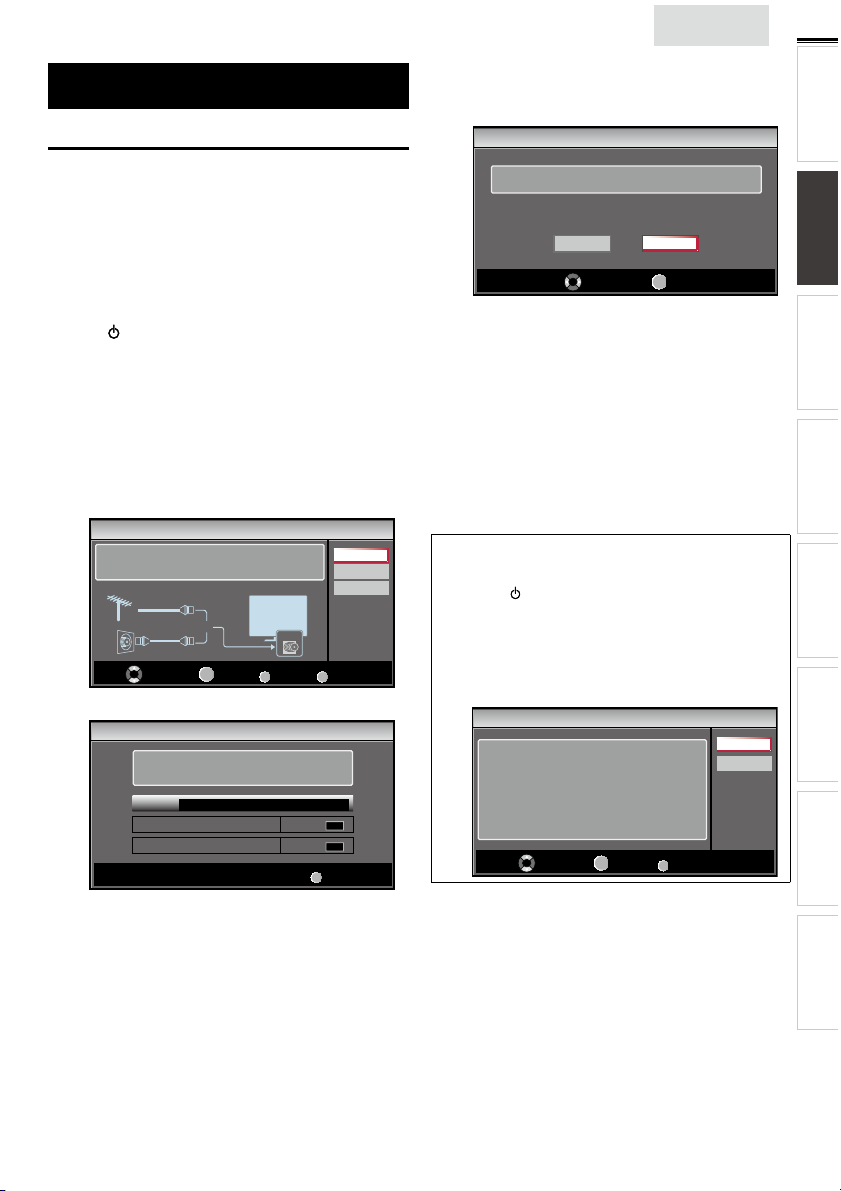
Initial Setup
This section will guide you through the unit’s initial setting
which includes selecting a language for your on-screen menu
and autoprogram, which automatically scans and memorizes
viewable channels.
Before you begin:
Make sure the unit is connected to antenna or cable.
1 After making all the necessary connections,
press
to turn on the unit.
• It may take a few moments to turn on the unit for the
first time.
• [Initial Setup] menu appears automatically after the
unit is turned on.
2 Use ▲/▼ to select the on-screen language from the
choices (English / Español / Français) on the right side of the
TV screen, then press OK.
3 Use ▲/▼ to select [Antenna] for TV channels or [Cable]
for CATV channels, then press OK.
Initial Setup
ANT.IN
0 ch
0 ch
Antenna
Cable
Skip
MENU
Skip
MENU
Skip
Make sure the antenna is connected to ''ANT. IN'' jack.
Select your signal source.
Antenna
Cable
Select
Or
OK
OK
• [Autoprogram] will begin.
Initial Setup
Please wait while the system is scanning for channels.
Auto programming may take more than 20 minutes to
complete.
0%
Digital channels
Analog channels
BACK
Back
English
4 Use ◄/► to select the desired location setting, then press
OK.
[Home] is ENERGY STAR
Initial Setup
Select “Retail” or “Home” for your location.
• Select [Retail] store, the unit will be set up with
predefined setting for retail displays. In this setting, the
power consumption may possibly exceed the limited
requirement of the ENERGY STAR
• Select [Home], the unit is set to maximize the energy
efficiency for home setting and it can be adjusted
through a choice of picture and sound quality according
to your preference.
• When the initial setup is completed, the lowest
memorized channel with the confirmation message of
the location setting will be displayed on the TV screen.
• You must set [Home] in step 4. Otherwise, [Picture]
and [Sound] settings you adjusted will not be
memorized after the unit goes into standby mode.
Note
• If you are not receiving a signal from your cable service, contact
the Cable provider.
• If you press or MENU during autoprogram, this setup of TV
channels will be canceled.
• The initial autoprogram function can be executed for either
[Antenna] or [Cable] only once. When you change the
connection (Antenna / Cable), set [Autoprogram] again. ➠ p. 21
• If there is no signal input from the antenna terminal and no
operation for several seconds after you turn on the unit, helpful
hints appears. Follow the instructions listed on the TV screen.
Initial Setup
No channel is registered.
Try Autoprogram again?
Verify that you have a cable connected to the “ANT. IN” jack
on the back of the TV, the channel installation process
searches this connection. If you are using a cable or satellite
box, please confirm the input which you have connected to the
box and press “SOURCE” key on the remote control to select
the appropriate source input.
Select
Retail
Select
OK
®
qualifi ed setting.
Home
OK
OK
®
MENU
OK
Skip
qualification.
Retry
Later
15
INTRODUCTION PREPARATION
WATCHING TV
USING FUNCTIONS OPERATING DVD
CONNECTING DEVICES
After an initial setup is completed...
• If you want to scan the channels automatically again.
[Autoprogram]
➠
p. 21
• You can add the desired cable and analog channels
unmemorized by autoprogram.
[Add Channels]
➠
p. 22
• If you want to change to another language.
[Language]
➠
p. 27
• If you want to change the location setting.
[Location]
➠
p. 26
INFORMATION USEFUL TIPS
Page 16

16
WATCHING TV
Sleep Timer can set the unit to go into standby mode after an incremental period of time.
Press SLEEP repeatedly to change the amount of time (increases
the time by 30 minutes up to 120 minutes).
Press SLEEP once to call up the display for checking the remaining time.
• To cancel sleep timer, press SLEEP repeatedly until [Sleep Off] is
displayed.
Switching Each Input Mode can easily switch with the remote control
between TV (ATSC or NTSC) and external devices when they are connected to the unit.
Press SOURCE or CH + repeatedly to cycle through the input modes.
e.g.) 32MD311B/32MD301B/26MD311B/26MD301B
Source
TV
Video
Component
HDMI1
HDMI2
• Pressing CH − reverses the direction of the input modes.
These may differ depending on what product you purchased. For example, 22MD311B,
*
19MD311B or 19MD301B will be displayed [HDMI1], [HDMI2] and [PC] instead.
11.1
DTV / TV channel
Freeze Mode can freeze the image shown on the TV screen for 5 minutes.
Press FREEZE to freeze the image.
• The sound output will not be paused.
• To cancel freeze mode, press any buttons except .
Freeze
Video Component
HDMI2 HDMI1
(or PC input)
Sleep 120min.
Channel Selection
Select channels by using CH + / − or the Number buttons.
• To select the memorized channels,
use CH + / − or the Number buttons.
• To select the non-memorized channels,
use the Number buttons.
To use the Number buttons
ATS C
- When selecting digital channel 11.1
Be sure to press • before entering the subchannel number.
NTSC
- When selecting cable or analog channel 11
Press PREV CH to return to the previously viewed channel.
Note
• [No Signal] will appear on the TV screen after the subchannel
broadcast is over.
• [Audio only program] message will appear on the TV screen, when you
receive only sound signal.
11.1
Page 17

English
TV Screen Display Mode 5 types of display modes can be selected when the broadcasting station is sending 16:9 or 4:3 video signal. And 3 types of display modes can be selected for PC input signal.
Press FORMAT repeatedly to switch the TV aspect ratio.
For 16:9 video signal
Normal
Wide
4:3 Movie expand
Zoom
For 4:3 video signal
Normal
Wide
For PC input signal through
Normal Dot By DotFull
For 22MD311B, 19MD311B and 19MD301B, PC input mode is available. They can only accept the PC input signal when the unit
*
is connected to a PC (VGA) Input jack.
16:9 Movie expand
Zoom
HDMI1
Input mode
Normal displays a 16:9 picture at its original size.
4:3 displays a 16:9 picture at a 4:3 size; the picture is
shortened horizontally. Sidebars appear on both edges
of the screen.
Movie expand displays a 16:9 picture that is
vertically stretched to fi ll the screen. This only crops
out the top of the picture.
Zoom displays a 16:9 picture at its maximum size
without changing its horizontal and vertical ratio.
Wide displays a horizontally stretched picture. This
crops out the left and right sides of the picture.
Normal displays a 4:3 picture at its original size.
Sidebars appear on both edges of the screen.
16:9 displays a 4:3 picture at a 16:9 size; the picture is
stretched horizontally to fi ll the screen.
Movie expand displays a 4:3 picture at a 16:9 size;
the picture is stretched more vertically at the top of
the screen. This crops out the top of the picture.
Zoom displays a 4:3 picture at a 16:9 size; at its
maximum size that is more vertically stretched to fi ll the
screen. This crops out the top and bottom of the picture.
Wide displays the picture with its center at the
original size and the edges stretched horizontally to fi ll
the screen.
Normal displays a proportionately stretched picture.
Sidebars appear on both edges of the screen.
Full displays a picture that is stretched out of
proportion horizontally to fi ll the screen.
Dot By Dot displays a picture in its original size.
17
INTRODUCTION
PREPARATION
WATCHING TV
USING FUNCTIONS OPERATING DVD
CONNECTING DEVICES
Sound Functions describe how to change the audio or the audio language as well as the volume.
Volume Adjustment
Use VOL + / − to adjust the volume.
Silence Mode
Press MUTE to turn off the sound temporarily.
will be displayed for a few seconds.
Mute
• Press MUTE again or VOL + / − to recover the original volume.
Volume 30
will be displayed for a few seconds when adjusting the volume.
Switching Audio Mode
ATS C
Press SAP/AUDIO repeatedly to cycle through the available
audio languages.
• Available languages differ depending on the broadcast.
• [Other] is displayed when the audio language cannot be
acquired, or the acquired languages are other than English,
Spanish or French.
English 1/3
11.1
NTSC
Press SAP/AUDIO to display the currently selected audio mode.
While receiving an MTS broadcast, press repeatedly to cycle
through the available audio channel.
e.g.) When all audio are available
SAP / STEREO SAP / MONO SAP / STEREO
STEREO : Outputs stereo-audio
SAP : Outputs second audio program
MONO : Outputs mono-audio
SAP / STEREO
hi!
hola!
salut!
INFORMATION USEFUL TIPS
11
Page 18

18
11-1
TV: TV-14
1080i
1080i
16:9
16:9HDHD
CC
CC
KABC
KABC
1 23 4
5
6, 7, 8
9
10
TV Screen Information
You can display the currently selected channel or other
information such as the audio mode on the TV screen.
In the digital mode, the detailed broadcasting information
for the current off the air channel such as program title and
program guides are displayed.
1 Press INFO.
ATS C
A Day of Memories
A Day of Memories
A quarter-century ago,which may now qualify as the
good old days of newspapering,run-of-paper sales
accounted for 80 percent of the industry's advertising
revenues.Department stores and supermarket were
NTSC
4
11
SAP / STEREO
480i
480i
TV-PG DLSV
5
4:3SDSD
4:3
6, 7, 8
CC
CC
9
10
1 program title
2 program guide
( The program guide added to broadcasting
information is displayed to a maximum of 4 lines.)
3 broadcast station
4 channel number
5 audio language (ATSC) / audio mode (NTSC)
[Switching Audio Mode]
6 effective scanning lines and scan mode
7 TV format
8 program’s image aspect ratio
9 CC (not available if closed caption is set to [Off])
10 child lock rating
➠
English 1/2
Rating
p. 17
2 Press INFO or BACK to hide the information.
Note
• When the program guide consists of more than 4 lines, use ▲/▼
to scroll to the next / previous lines.
• [No description provided.] is displayed when the program guide
is not provided.
• While the program guide is displayed, the closed caption function
is interrupted.
• In external input mode, the following screen is displayed;
e.g.) When an external device is connected to Video Input jack.
Video
SD
480i
SD
480i
CC
CC
TV-PG DLSV
• The information display will automatically disappear in 1 minute.
Page 19

USING FUNCTIONS
This section describes the overview of the main menu
displayed when you press MENU.
The main menu consists of the function setting items below.
1 Press MENU to display
the main menu.
English
2 Use ▲/▼ to select a desired menu and an item, then
press OK to determine the setting.
19
INTRODUCTION
PREPARATION WATCHING TV
Picture
Sound
Channel
Features
Language
DVD
Picture
Adjusting the picture mode, or customize the
picture quality as your preference.
Sound
Adjusting the sound mode, equalizer and some
other sound functions.
Channel
Scanning the channels available in your area and
see what the antenna levels are.
Features
Adjusting the Closed Caption, parental guide and
some other useful functions.
Language
You can choose English, Spanish, or French
as your on-screen language.
Page 20
Page 20
Page 21
Page 22
Page 27
USING FUNCTIONS
OPERATING DVD
CONNECTING DEVICES
DVD
You can choose the desired DVD settings.
Page 27
3 When the setting is completed, press MENU to exit.
INFORMATION USEFUL TIPS
Page 20

20
Picture
Before you begin:
You must set [Home] in [Location]. ➠ p. 26
Otherwise, the settings you adjusted will not be memorized
after the unit goes into standby mode.
1 Use ▲/▼ to select the item you want to adjust, then press
OK.
Picture
Sound
Channel
Features
Language
DVD
Smart Picture
Brightness
Contrast
Color
Tint
Sharpness
Color Temperature
Personal
30
60
36
0
0
Normal
2 Adjust the following items.
Smart Picture
Use ▲/▼ to select the desired setting, then press OK.
([Personal], [Standard], [Sports], [Movie], and [Game])
Brightness, Contrast, Color, Tint, Sharpness,
Color Temperature
You can only adjust the following options when you set to
[Personal] in [Smart Picture].
Use ▲/▼ to select the desired setting, then press OK. Then
use ◄/► to adjust the setting.
Cursor ◄ Cursor ►
Brightness to decrease brightness to increase brightness
Contrast to decrease contrast to increase contrast
Color
Tint to add red to add green
Sharpness to soften to sharpen
Color
Temperature
to decrease color
intensity
to add warm colors to add cool colors
to increase color
intensity
Sound
Before you begin:
You must set [Home] in [Location]. ➠ p. 26
Otherwise, the settings you adjusted will not be memorized
after the unit goes into standby mode.
1 Use ▲/▼ to select the item you want to adjust, then press
OK.
Picture
Sound
Channel
Features
Language
DVD
[Auto Volume Leveling] will only display for 32MD311B,
*
32MD301B, 26MD311B and 26MD301B.
Smart Sound
Equalizer
Auto Volume Leveling
TV Speakers
Primary MTS
Standard
Off
Ext. Amp
Stereo
2 Adjust the following items.
Smart Sound
Use ▲/▼ to select the desired setting, then press OK.
([Personal], [Standard], [Movie], [Music], and [News])
Equalizer
Adjust tonal quality for each frequency.
Use ◄/► to select the specifi c frequency and use ▲/▼ to
adjust the level, then press OK.
Auto Volume Leveling
This function keeps a constant loudness differential between
the TV commercials and the programs.
Use ▲/▼ to select the desired option, then press OK.
On
Off Removes the auto volume leveling.
TV Speakers
Select the audio output from the unit’s speakers, or not. If your
amplifi er is HDMI link function compatible and connected by
an HDMI cable to this unit, some sound operations such as
volume up can be changed by using this unit’s remote control.
Make sure [fun-Link Control] is set to [On].
Use ▲/▼ to select the desired option, then press OK.
On The sound will be output from the unit’s speakers.
Off
Ext. Amp
Note
• We do not guarantee 100% interoperability with other brands of
HDMI link compliant devices.
Primary MTS
You can set the output mode as a default for the sound mode
(NTSC only).
This setting is not interlocked when you change the output
mode by pressing SAP/AUDIO. [Sound Functions]
Use ▲/▼ to select the desired option, then press OK.
Stereo Outputs stereo-audio.
Mono Outputs mono-audio.
SAP Outputs second audio program.
Reduces volume differences between the
TV commercials and the programs.
p. 26
➠
The sound will not be output from the unit’s
speakers.
You can control audio output from your
connected HDMI link devices by using this unit's
remote control.
p. 17
➠
*
Page 21

Channel
Before you begin:
Make sure the unit is connected to antenna or cable.
1 Use ▲/▼ to select the item you want to adjust, then press
OK.
Picture
Sound
Channel
Features
Language
DVD
Autoprogram
Channel List
Add Channels
Antenna
2 Adjust the following items.
Autoprogram
If you switch wires (e.g. between antenna and CATV) or if you
move the unit to a different area after the initial setting, or if
you restore the DTV channels you deleted, it is recommended
to use Autoprogram to perform a new channel search.
1 Use ▲/▼ to select [Autoprogram], then press OK.
2 Use ▲/▼ to select an appropriate option, then press OK.
ANT.IN
Back
Antenna
Cable
Picture
Sound
Channel
Features
Language
DVD
Autoprogram will rescan all channels.
Auto programming may take more than 20
minutes to complete.
Select your signal source.
Antenna
Cable
Or
• When connected to VHF / UHF antenna, select [Antenna].
• When connected to CATV, select [Cable].
• [Autoprogram] will begin.
English
Note
• After setting [Autoprogram], using CH + / − on the remote control
skips unavailable programs automatically.
• If you are not receiving a signal from your cable service, contact
the Cable provider.
• If you press
channels will be canceled.
• Even if [Autoprogram] is completed, the channel setting will be
lost if the AC power cord is unplugged before the unit goes into
standby mode by pressing
• The PIN code will be required once you set a PIN code in the
[Child Lock]. ➠ p. 23
• If you want to change your PIN code, follow the instruction of
[Change PIN]. ➠ p. 25
Channel List
The channels selected here can be skipped when selecting the
or MENU during autoprogram, the setup of TV
.
channels using CH + / −.
Those channels can still be selected with the Number buttons.
1 Use ▲/▼ to select [Channel List], then press OK.
2 Use ▲/▼ to select the channel you want to remove, then
press OK.
Watch / Skip
DTV 11.1
DTV 11.2
DTV 11.3
BACK
Back
Picture
Sound
Channel
Features
Language
DVD
• The channel display for the removed channel darkens.
You will not be able to select the channel again using
CH + / −.
• To reactivate a removed channel, use ▲/▼ and press
OK. The registered channels are highlighted.
Highlight channels for
Ch Up / Down key selection.
Ch Select
OK
• When you remove a main channel, its subchannels are
removed as well.
Note
• The channel with the [DTV] indicated on the display is ATSC.
Otherwise the channel is NTSC.
21
INTRODUCTION
PREPARATION WATCHING TV
USING FUNCTIONS
OPERATING DVD
CONNECTING DEVICES
Please wait while the system is scanning for channels.
Auto programming may take more than 20 minutes to complete.
75%
Digital channels
Analog channels
MENU
• When the scanning and memorizing are completed, the
lowest memorized channel will be displayed.
Exit
10 ch
6 ch
INFORMATION USEFUL TIPS
Page 22

22
A. Caption Service
Add Channels
This function lets you add the off the air along NTSC or analog
Cable channels that were not added by the autoprogram due
to reception conditions at the initial setting.
1 Use ▲/▼ to select [Add Channels], then press OK.
2 Use the Number buttons to enter the number of the
channel you want to add, then press OK.
11
Picture
Sound
Channel
Features
Language
DVD
For analog channels, select a
channel to be added using
number keys.
For digital channels, you must
perform Autoprogram function.
Ch Change
Note
• If setup completes successfully, [Added to the channel list.] is
displayed.
• If external input is used, it is not possible to register the channel
and [Unavailable] will be displayed on the TV screen.
• By using CH + / −, you can select the memorized channels only.
Antenna Confi rmation
ATS C
This function lets you check the digital signal strength of each
channel.
Add channels
BACK
Back
Features
1 Use ▲/▼ to select the item you want to adjust, then press
OK.
Picture
Sound
Channel
Features
Language
DVD
[PC Settings] will only display for 22MD311B, 19MD311B or
*
19MD301B.
Closed Caption
Child Lock
PC Settings
fun-Link (HDMI CEC)
Energy Saving Mode
Location
Current Software Info
On
Home
2 Adjust the following items.
Closed Caption
You can view closed captioning (CC) for TV programs,
movies and news. Closed caption refers to text of dialog or
descriptions displayed on-screen.
Use ▲/▼ to select [Closed Caption], then press OK.
See the following description for setting each item.
Picture
Sound
Channel
Features
Language
DVD
Caption Service
Digital Caption Service
Caption Style
On
On
A
B
C
*
1 Use ▲/▼ to select [Antenna], then press OK.
2 Use the Number buttons or CH + / − to select the channel
for which you want to check the digital signal strength.
11.1
Picture
Sound
Channel
Features
Language
DVD
Current 50 Max 50
Ch Change
Note
• If the channel is set to analog channel or external input, you
cannot confi rm the antenna condition.
Back
A. Caption Service
1 Use ▲/▼ to select [Caption Service], then press OK.
2 Use ▲/▼ to select the desired closed caption, then press
OK.
Off Select if you do not want caption service .
CC-1 and T-1
CC-3 and T-3
CC-2, CC-4,
T-2 and T-4
• There are 3 display modes according to programs:
Paint-on
mode
Pop-on mode
Roll-up mode
The primary caption and text ser vices. The
captioning or text is displayed in the same language
as the program’s dialog (up to 4 lines of script on the
TV screen, where it does not obstruct relevant parts
of the picture).
Serve as the preferred data channels.
The captioning or text is often a secondary
language.
Rarely available and broadcasters use them only in
special conditions, such as when [CC-1] and [CC-3]
or [T-1] and [T-3] are not available.
Displays input characters on the TV screen
immediately.
Once characters are stored in memor y, they are
displayed all at once.
Displays the characters continuously by scrolling
(max. 4 lines).
Page 23

B. Digital Caption Service
B. Digital Caption Service
C. Caption Style
So, y ou m us t be P hi li p. Hi !
I’m p le as ed t o me et y ou .
Background
( Background Color and Background Opacity or
Transparency)
Picture display
Edge
(Edge Color and Edge Type)
Font
( Font Style, Font Size, Font Color and Font Opacity or
Transparency)
ATS C
In addition to the basic closed caption, DTV has its own closed
caption called digital caption service. Use this menu to change
the settings for digital caption service.
1 Use ▲/▼ to select [Digital Caption Service], then press
OK.
2 Use ▲/▼ to select the desired digital caption service, then
press OK.
Off
Select if you do not want digital caption
service.
Select one of these before changing any
CS-1 to CS-6
other item in [Closed Caption] menu.
Choose [CS-1] under normal circumstances.
Note
• [Digital Caption Service] that you can switch differs depending on
the broadcast description.
C. Caption Style
ATS C
You can change the caption style such as font, color or size, etc.
1 Use ▲/▼ to select [Caption Style], then press OK.
2 Use ▲/▼ to select [User Setting], then press OK.
3 Use ▲/▼ to select [On], then press OK.
4 Use ▲/▼ to select an item, then press OK. Then use
▲/▼ to select the desired setting and press OK.
Picture display
English
Note
• Closed caption will not be displayed when you are using an HDMI
connection.
• To show the closed caption on your TV screen, broadcast signal
must contain the closed caption data.
• Not all TV programs and commercials have the closed caption or
all types of the closed caption.
• Captions and texts may not exactly match the TV voice.
• Changing channels may delay the closed caption for a few seconds.
• Adjusting or muting the volume may delay the closed caption for
a few seconds.
• Abbreviations, symbols and other grammatical shortcuts may be
used in order to keep pace with the on-screen action. This is not
a malfunction.
• The caption or text characters will not be displayed while the
main menu or functions display is shown.
• If a black box appears on the TV screen, this means that the closed
caption is set to the text mode. To clear the box, select [CC-1],
[CC-2], [CC-3], [CC-4] or [Off].
• If the unit receives poor quality television signals, the captions may
contain errors, or there might be no captions at all. Some possible
causes of poor quality signals are:
- Automobile ignition noise
- Electric motor noise
- Weak signal reception
- Multiplex signal reception (ghosts or screen fl utter)
- Data dropout and Pixelation (for DTV only)
• The unit retains the closed caption setting if the power fails.
• When the unit receives special effects playback signal (e.g. Search,
Slow and Still) from a VCR’s video output channel (ch3 or ch4),
the unit may not display the correct caption or text.
Child Lock
Child lock reads the ratings for programs, then denies access
to the programs which exceed the rating level you set. With
this function, you can block certain programs inappropriate
for children and any channels or external input modes can be
invisible.
1 Use ▲/▼ to select [Child Lock], then press OK.
23
INTRODUCTION
PREPARATION WATCHING TV
USING FUNCTIONS
OPERATING DVD
CONNECTING DEVICES
So, you must be Philip. Hi!
So, you must be Philip. Hi!
I’m pleased to meet you.
I’m pleased to meet you.
Edge
(Edge Color and Edge Type)
Font
( Font Style, Font Size, Font Color and Font Opacity or
Transparency)
Background
( Background Color and Background Opacity or
Transparency)
• Review your setting choice made below by looking in
the upper right corner of the displayed setting box (not
all selections show the differences selected).
Font Style
Font
Background
Edge
Font Size
Font Color
Font
Opacity
Background
Color
Background
Opacity
Edge Color
Edge Type
Closed captioning font style, size,
color and opacity can be changed.
Background color and opacity of the
displayed caption can be switched.
Edge color and type of the displayed
caption can be switched.
Picture
Sound
Channel
Features
Language
DVD
[PC Settings] will only display for 22MD311B, 19MD311B or
*
19MD301B.
Closed Caption
Child Lock
PC Settings
fun-Link (HDMI CEC)
Energy Saving Mode
Location
Current Software Info
On
Home
*
INFORMATION USEFUL TIPS
Page 24

24
A. Channel Lock
B. Setting US Movie ratings
C. Setting TV ratings
2 Use the Number buttons to enter the 4-digit number for
your PIN code.
Features
Language
• When you have not set up your PIN code,
enter 0, 0, 0, 0.
• When the PIN code is correct, [Child Lock] menu is
displayed.
Enter PIN.
• See the following description for setting each item.
Picture
Sound
Channel
Features
Language
DVD
Channel Lock
US Movie Ratings Lock
US TV Ratings Lock
Canadian English Rating
Canadian French Rating
Region Ratings Lock
Clear Region Ratings Lock
Change PIN
Note
• When you select a rating and set it to [Block], the higher ratings
will be blocked automatically. The lower ratings will be available for
viewing.
• When you set the highest rating to [View], all ratings turn to
[View] automatically.
• To block any inappropriate programs, set your limits in [US Movie
Ratings Lock], [US TV Ratings Lock] and [Region Ratings Lock].
• The child lock setting will be retained after a power failure or after
the power is removed for longer than 10 seconds (except the PIN
code reverts to 0000). [Child Lock] ➠ p.23
• If the rating is blocked, will appear.
• [Region Ratings Lock] will be available when the unit receives a
digital broadcast using the new rating system.
• For the United States, the unit may download the Region Ratings
Lock Table, if required.
• The Canadian rating systems on this unit are based on CEA-766-A
and CRTC policy.
A. Channel Lock
Particular channels or external input modes can be invisible in
this function.
1 Use ▲/▼ to select [Channel Lock], then press OK.
2 Use ▲/▼ to select the desired rating, then press OK
repeatedly to switch between [View] and [Block].
Picture
Sound
Channel
Features
Language
DVD
Select
These may differ depending on what product you purchased.
*
For example, 22MD311B, 19MD311B or 19MD301B will be
displayed [PC] and [DVD] instead.
Video
Component
HDMI1
HDMI2
DVD
40.1 DTV
OK
View / Block
_
BACK
Back
B. Setting US Movie ratings
US Movie ratings lock is the rating system created by MPAA.
1 Use ▲/▼ to select [US Movie Ratings Lock], then press
OK.
2 Use ▲/▼ to select the desired rating, then press OK
repeatedly to switch between [View] and [Block].
Picture
A
B
C
Sound
Channel
Features
Language
DVD
D
Rating Category
X Mature audience only
NC-17 No one under 17 admitted
R
PG-13 Unsuitable for children under 13
PG Parental guidance suggested
G General audience
NR No rating
C. Setting TV ratings
Restricted; under 17 requires accompanying
parent or adult guardian
Select
X
NC-17
R
PG-13
PG
G
NR
OK
View / Block
1 Use ▲/▼ to select [US TV Ratings Lock], then press OK.
2 Use ▲/▼ / ◄/► to select the desired rating, then press
OK repeatedly to switch between [View] and [Block].
Picture
Sound
Channel
Features
Language
DVD
TV-MA
TV-14
TV-PG
TV-G
TV-Y7
TV-Y
Select
FV V S L D
OK
View / Block
Rating Category
TV-MA Mature audience only higher
TV-14 Unsuitable for children under 14
TV-PG Parental guidance suggested
TV-G General audience
TV-Y7
Appropriate for all children 7 and
older
TV-Y Appropriate for all children lower
BACK
Back
BACK
Back
Page 25

To set the sub ratings
D. Change PIN
As for TV-MA, TV-14, TV-PG, or TV-Y7, you can further set the
sub ratings to block specifi c elements of programming. To set
the sub ratings, follow the step below.
Use ▲/▼ / ◄/► to select the desired rating, then press OK
repeatedly to switch between [View] and [Block].
Picture
Sound
Channel
Features
Language
DVD
TV-MA
TV-14
TV-PG
TV-G
TV-Y7
TV-Y
Sub Rating Category Rating
FV Fantasy Violence TV-Y7
V Violence
S Sexual Situation
L Coarse Language
D Suggestive Dialog TV-14, TV-PG
Note
• Blocked sub rating will appear beside the main rating category in
[US TV Ratings Lock] menu.
• You cannot block a sub rating (D, L, S or V) if the main rating is set
to [View].
• Changing the category to [Block] or [View] automatically changes
all its sub ratings to the same ([Block] or [View]).
Select
FV V S L D
View / Block
BACK
TV-MA
TV-14
TV-PG
OK
Back
English
PC Settings
This function lets you adjust the PC screen position, clock and
phase during PC input.
<22MD311B, 19MD311B and 19MD301B only>
1 Use ▲/▼ to select [PC Settings], then press OK.
2 Use ▲/▼ to select the setting you want to adjust, then
press OK.
Picture
Sound
Channel
Features
Language
DVD
Auto Adjustment
Horizontal Position
Vertical Position
Clock
Phase
0
0
0
0
3 Adjust the following items.
Auto Adjustment
Use ▲/▼ to select [Adjust], then press OK.
Picture
Sound
Channel
Features
Language
DVD
To automatically synchronize
the phase and clock
on the TV and PC.
Cancel
Adjust
25
INTRODUCTION
PREPARATION WATCHING TV
USING FUNCTIONS
OPERATING DVD
D. Change PIN
Although the default PIN code (0000) is supplied with the unit,
you can set your own PIN code.
1 Use ▲/▼ to select [Change PIN], then press OK.
2 Press the Number buttons to enter the new 4-digit PIN
code.
• Enter PIN code again in [Confirm PIN.] entry field.
Picture
Sound
Channel
Features
Language
DVD
Enter PIN.
Confirm PIN.
PIN Code
Note
• Make sure new PIN code and confi rm PIN code must be exactly
the same. If they are different, the space is cleared for reentering.
• Your PIN code will be erased and returns to the default PIN code
(0000) when a power failure occurs.
• If you forget the PIN code, unplug the AC power cord then wait
for 10 seconds to plug the AC power cord in again.
The unit will restore the PIN code to 0000 as the factory default.
_
BACK
Back
• The horizontal/vertical position, clock and phase of the
PC screen are automatically adjusted.
Horizontal Position, Vertical Position
Use ◄/► to adjust.
Horizontal
Position
Vertical
Position
Cursor ◄ Cursor ►
to move PC screen left to move PC screen right
to move PC screen
down
to move PC screen up
Clock, Phase
Use ◄/► to adjust [Clock] setting to stabilize
the PC screen and [Phase] setting to improve the clarity
of the PC screen.
Cursor ◄ Cursor ►
Clock
Phase
Note
• You may not obtain an appropriate screen with
[Auto Adjustment] for some signals. In this case, adjust the settings
manually.
• Adjust [Phase] setting after [Clock] setting has been properly
adjusted.
to decrease setting
value
to increase setting
value
CONNECTING DEVICES
INFORMATION USEFUL TIPS
Page 26

26
fun-Link (HDMI CEC)
This function allows you to operate the linked functions
between our brand devices with a fun-Link feature and this
unit connecting through an HDMI cable.
1 Use ▲/▼ to select [fun-Link (HDMI CEC)], then press
OK.
Picture
Sound
Channel
Features
Language
DVD
fun-Link Control
Auto Device Off
Auto TV On
Device List
On
On
On
2 Use ▲/▼ to select the desired setting, then press OK.
3 Adjust the following items.
fun-Link Control
Set the fun-Link [On] or [Off].
The following additional settings will be grayed out when you
set to [Off].
Use ▲/▼ to select the desired setting, then press OK.
On
Off Disables all fun-Link.
Auto Device Off
You can set your device to turn off by interlocking from this
unit’s power.
Use ▲/▼ to select the desired setting, then press OK.
On
Off
Auto TV On
This unit will turn on detected when the power on signal is
sent from your connected fun-Link device.
Use ▲/▼ to select the desired setting, then press OK.
On
Off
Selects if you have connected an external device
that is compatible with the fun-Link function.
Your connected fun-Link device turns off
automatically when the unit goes into standby
mode.
Your connected fun-Link device stays on even if
the unit goes into standby mode.
This unit turns on automatically when you turn on
your connected fun-Link device.
This unit stays the standby mode even if you turn
on your connected fun-Link device.
Device List
This function lets you see the product model number or name
of connected devices.
Use ▲/▼ to select the desired HDMI device listed on the TV
screen, then press OK.
Picture
Sound
Channel
Features
Language
DVD
HDMI1
NB620SL2
HDMI2 MBP5230
OK
Select
Input Change
BACK
Back
Energy Saving Mode
You can set whether the power consumption is saved or not.
1 Use ▲/▼ to select [Energy Saving Mode], then press OK.
2 Use ▲/▼ to select the desired mode, then press OK.
On Reduces the power consumption.
Off
Note
• You must set [Home] in [Location]. ➠ p. 26
Otherwise, the settings you adjusted will not be memorized after
the unit goes into standby mode.
Location
When you select [Retail] store, the power consumption may
possibly exceed the limited requirement of the
ENERGY STAR
The power consumption may possibly exceed
the limited requirement of the ENERGY STAR
qualification.
®
qualifi cation.
®
1 Use ▲/▼ to select [Location], then press OK.
2 Use ▲/▼ to select the desired location, then press OK.
The unit will be set up with predefined setting
Retail
Home
for retail displays. In this setting, the power
consumption may possibly exceed the limited
requirement of the ENERGY STAR
This setting is ENERGY STAR
The unit is set to maximize the energy efficiency
for home setting and it can be adjusted through a
choice of picture and sound quality according to
your preference.
®
qualification.
®
qualification.
Page 27

Current Software Info
This function shows what version of the software currently
used.
1 Use ▲/▼ to select [Current Software Info], then press
OK.
2 Confi rm the version of the software currently used.
English
DVD
Settings are only effective when the unit is in DVD mode
and any discs should not be played back.
1 Use ◄/►to select a desired setting and an item, then press
OK to determine the setting.
27
INTRODUCTION
PREPARATION WATCHING TV
Picture
Sound
Channel
Features
Language
DVD
Release Version:
XXXXXXX_XXX_X_XXXX
Back
Language
Use ▲/▼ to select [English], [Español] or [Français], then
press OK.
Picture
Sound
Channel
Features
Language
DVD
Note
• If you need the English menus instead of the Spanish or French
menus, press MENU. Use ▲/▼ to select [Idioma] or [Langue],
then press OK.
Use ▲/▼ to select [English], then press OK.
Press MENU to exit the main menu.
Select your menu language.
Seleccione el idioma para el menú.
Sélectionnez la langue du menu.
English
Español
Français
LANGUAGE
AUDIO ORIGINAL
SUBTITLE OFF
DISC MENU ENGLISH
ENTER/OK
2 When the setting is completed, press MENU to exit.
DVD Language Setting
You can change the desired language when playing back the disc.
1 Use ▲/▼ to select the item you want to adjust, then press
OK.
2 Adjust the following items.
AUDIO *1, *2
Select the desired audio language.
SUBTITLE *1, *2
Select the desired subtitle language.
DISC MENU *1
Select the desired language in DVD menu.
Note
• To change the on-screen language, call up [Language] from the
main menu and set the desired language. [Language] ➠ p. 27
*1
• Language options are not available with some discs.
• If [OTHER] is selected in [
[DISC MENU] menu, press 4-digit number to enter the code for
the desired language. [Language Code List]. ➠ p. 29
• Only the languages supported by the disc can be selected.
*2
• Language setting for Audio and Subtitle are not available with
some discs.
-
Use MODE to select subtitles available on the DVD.
-
Use SAP/AUDIO to select audio available on the DVD.
• If the DVD’s default settings for audio and subtitle are the same
language, the subtitles may not show unless you turn them on.
(Default: ORIGINAL)
AUDIO
], [SUBTITLE] or
(Default: OFF)
(Default: ENGLISH)
USING FUNCTIONS
OPERATING DVD
CONNECTING DEVICES
INFORMATION USEFUL TIPS
Page 28

28
DVD Audio Setting
Choose the appropriate audio settings for your equipment. It only
affects during the playback of DVD.
1 Use ▲/▼ to select the desired item, then press OK.
AUDIO
DRC ON
DOWN SAMPLING ON
DOLBY DIGITAL BITSTREAM
ENTER/OK
2 Adjust the following items.
DRC (dynamic range control)
This function is available only on the discs which are recorded
in the Dolby Digital format.
ON
OFF No effects (original sound).
Compress the range between soft and loud
sounds.
DOWN SAMPLING
This function is available only on digital outputting of a disc
recorded in 96kHz.
ON When outputting in 48kHz.
OFF When outputting the original sound.
Note
• When playing back a 96 kHz disc with the copyright protection
or when [Virtual Surround] is set to [1] or [2], the sound will be
down sampled at 48 kHz even if the [DOWN SAMPLING] is set
to [OFF]. [Virtual Surround]. ➠ p. 35
DOLBY DIGITAL
Set to [BITSTREAM] when this unit is connected to a Dolby
Digital decoder.
BITSTREAM Outputs Dolby Digital signals.
PCM
Converts the Dolby Digital into PCM. (2 channel)
(Default: ON)
(Default: ON)
(Default: BITSTREAM)
Parental Setting
Parental setting prevents your children from viewing inappropriate
materials. (password protected.) Playback will stop if the ratings
exceed the levels you set.
1 Use the Number buttons to enter the 4-digit password for
your password, then press OK.
PARENTAL
PASSWORD
Please enter a 4-digit password.
ENTER/OK
• If you have set password already, use
the Number buttons to enter the current 4-digit
password.
• You cannot use the default password (4737) to play
back a DVD.
2 Use ▲/▼ to select the [PARENTAL LEVEL], then press
OK.
3 Use ▲/▼ to select the desired item, then press OK.
PARENTAL LEVEL
ALL
8 [ADULT]
7 [NC-17]-2 [G]
1 [KID SAFE]
All parental locks are cancelled.
All ratings (adult / gener al / children) can be
played back.
Only DVD intended for general use and
children can be played back.
Only DVD intended for children can be played
back.
To change the password
4 At step 2, use ▲/▼ to select [PASSWORD CHANGE]
then press OK.
5 Use the Number buttons to enter the new 4-digit
password.
Note
• DVD-video may not respond to parental lock settings. Make sure
this function works with your DVD-video.
• Record the password in case you forget it.
• If you forget the password, press 4, 7, 3, 7, then enter your new
password. Password will be cleared and parental levels will be set
to [ALL].
• A power failure will not erase your password.
Page 29

Others
You can change the other functions.
1 Use ▲/▼ to select the desired item, then press OK.
OTHERS
ANGLE ICON ON
STILL MODE AUTO
AUTO POWER OFF ON
ENTER/OK
2 Adjust the following items.
ANGLE ICON
Set to [ON] to show the angle icon when multiple camera
angles are available during DVD playback.
STILL MODE
Set the picture quality in the still mode.
If you select [AUTO], it automatically selects the best
resolution setting ([FRAME] or [FIELD]) based on the date
characteristics of the pictures.
FIELD
FRAME
The picture in the still mode will be stabilized.
The picture in the still mode will be highly defined.
AUTO POWER OFF
Set to [ON] if there is no operation for 20 minutes, the unit
goes into standby mode.
Reset to the Default Setting
You can reset all the settings except for the parental setting and
on-screen menu language.
(Default: ON)
(Default: AUTO)
(Default: ON)
1 Use ▲/▼ to select [YES], then press OK.
INITIALIZE
Initialize?
NO
YES
ENTER/OK
Note
• When you want to cancel the initialization, select [NO], then press
OK.
English
Language Code List
Language Code Language Code
Abkhazian 4748
Afar 4747
Afrikaans 4752
Albanian 6563
Amharic 4759
Arabic 4764
Armenian 5471
Assamese 4765
Aymara 4771
Azerbaijani 4772
Bashkir 4847
Basque 5167
Bengali;Bangla 4860
Bhutani 5072
Bihari 4854
Bislama 4855
Breton 4864
Bulgarian 4853
Burmese 5971
Byelorussian 4851
Cambodian 5759
Catalan 4947
Chinese [CHI] 7254
Corsican 4961
Croatian 5464
Czech [CZE] 4965
Danish [DAN] 5047
Dutch [DUT] 6058
English [ENG] 5160
Esperanto 5161
Estonian 5166
Faroese 5261
Fiji 5256
Finnish [FIN] 5255
French [FRE] 5264
Frisian 5271
Galician 5358
Georgian 5747
German [GER] 5051
Greek [GRE] 5158
Greenlandic 5758
Guarani 5360
Gujarati 5367
Hausa 5447
Hebrew 5569
Hindi 5455
Hungarian [HUN] 5467
Icelandic [ICE] 5565
Indonesian 5560
Interlingua 5547
Interlingue 5551
Inupiak 5557
Irish [IRI] 5347
Italian [ITA] 5566
Japanese [JPN] 5647
Javanese 5669
Kannada 5760
Kashmiri 5765
Kazakh 5757
Kinyarwanda 6469
Kirghiz 5771
Kirundi 6460
Korean [KOR] 5761
Kurdish 5767
Laothian 5861
Latin 5847
Latvian;Lettish 5868
Lingala 5860
A-B
C-E
F-H
I-K
L-N
Note
• If you choose a language that has a 3-letter abbreviation, the code
will be displayed every time you change the audio or subtitle
language setting above. If you choose any other language, [---] will
be displayed instead. (3-letter abbreviation is written in bracket.)
Lithuanian 5866
Macedonian 5957
Malagasy 5953
Malay 5965
Malayalam 5958
Maltese 5966
Maori 5955
Marathi 5964
Moldavian 5961
Mongolian 5960
Nauru 6047
Nepali 6051
Norwegian [NOR] 6061
Occitan 6149
Oriya 6164
Oromo(Afan) 6159
Panjabi 6247
Pashto;Pushto 6265
Persian 5247
Polish [POL] 6258
Portuguese [POR] 6266
Quechua 6367
Rhaeto-Romance 6459
Romanian [RUM] 6461
Russian [RUS] 6467
Samoan 6559
Sangho 6553
Sanskrit 6547
Scots Gaelic 5350
Serbian 6564
Serbo-Croatian 6554
Sesotho 6566
Setswana 6660
Shona 6560
Sindhi 6550
Singhalese 6555
Siswat 6565
Slovak 6557
Slovenian 6558
Somali 6561
Spanish [SPA] 5165
Sundanese 6567
Swahili 6569
Swedish [SWE] 6568
Tagalog 6658
Tajik 6653
Tamil 6647
Tatar 6666
Telugu 6651
Thai 6654
Tibetan 4861
Tigrinya 6655
Tonga 6661
Tsonga 6665
Turkish [TUR] 6664
Turkmen 6657
Twi 6669
Ukrainian 6757
Urdu 6764
Uzbek 6772
Vietnamese 6855
Volapuk 6861
Welsh 4971
Wolof 6961
Xhosa 7054
Yiddish 5655
Yoruba 7161
Zulu 7267
O-R
S
T
U-Z
29
INTRODUCTION
PREPARATION WATCHING TV
USING FUNCTIONS
OPERATING DVD
CONNECTING DEVICES
INFORMATION USEFUL TIPS
Page 30

30
OPERATING DVD
Playable Media
Media Type Logo
DVD-VIDEO
DVD-RW
DVD-R
CD-DA
CD-RW
CD-R
Region Codes
This unit has been designed to play back DVD with
region 1. DVD must be labeled for ALL regions or
for region 1 in order to play back on the unit. You
cannot play back DVD that are labeled for other
regions. Look for the symbols on your DVD. If these
region symbols are not on your DVD, you cannot
play back the DVD in this unit.
The number inside the globe refers to region of the world.
A DVD labeled for a specifi c region can only be played back
on the unit with the same region code.
Color Systems
DVD is recorded in different color systems throughout the
world. The most common color system is NTSC (which is used
primarily in the United States and Canada).
This unit uses NTSC, so DVD you play back must be recorded
in the NTSC system. You cannot play back DVD recorded in
PAL color systems.
Recorded
Signal
digital video
(MPEG2)
digital audio
Media Size
5 inches
(12 cm)
Unplayable Media
NEVER play back the following discs. Otherwise, malfunction
may result!
• 3 inches (8 cm) disc
• DVD-RAM
• DVD-audio
• CD-i
• Photo CD
• Video CD
• DVD with region codes other than 1 or ALL
• DTS-CD
• DVD-ROM for personal computers
• CD-ROM for personal computers
• The discs with labels, scratches, stains, blemishes, etc.
• HD DVD
• Blu-ray Disc
• DVD or CD contains MP3 / JPEG fi les
• KODAK Picture CD
On the following disc, the sound MAY NOT be heard.
• Super audio CD
Any other discs without compatibility indications
Note
•Unfi nalized discs cannot be played back.
• For DVD-RW/-R, discs recorded in the VR (video recording)
format cannot be played back. Only the fi nalized video format
discs can be played back.
• Some discs cannot be played back because of incompatible
recording conditions, characteristics of the recorder or special
properties of discs.
• Only the sound recorded on the normal CD layer can be
delivered. The sound recorded on the high density super audio
CD layer cannot be delivered.
• Do not use a single CD adaptor which makes 3 inches (8 cm) to
5 inches (12 cm) disc.
• You can play back discs with the marks listed in [Playable Media].
If you use non-standardized discs, this unit may not play them back
or the sound and video quality will be compromised.
• If the recorded portion of the disc is too small (less than 2.17
inches (55 mm) across), it may not play back properly.
Page 31

These operations are accessible by remote control. Some
may also be accessible by controls on the main unit.
Playback
Before you begin:
Turn on the amplifi er and any other equipment which is
connected to this unit.
included) are set to the correct channel.
Make sure the external audio receiver (not
1 Press to turn on the unit.
2 Inser t a disc with label facing forward.
<32MD311B / 32MD301B>
English
Disc Menu
DVD
Some discs contain disc menus which describe the contents of the
disc or allow you to customize disc playback, or title menu which
lists the titles available on the DVD.
To display the DVD menu, press DISC MENU and use
▲/▼/◄/► to select an item, then press OK (or PLAY B).
To display the top menu, press TITLE and use
▲/▼/◄/► to select an item, then press OK (or PLAY B).
Note
• Menu operations may vary depending on the disc.
Refer to the manual accompanying the disc for more details.
31
INTRODUCTION
PREPARATION WATCHING TV
label
<26MD311B / 26MD301B / 22MD311B / 19MD311B / 19MD301B>
label
• In case the DVD was recorded on both sides, make
sure the label of the side you want to play back is facing
forward.
#
CAUTION
• Do not put coins or
foreign objects into
the disc loading slot.
3 The unit switches to the DVD mode when the unit was in
TV mode and detects the type of disc.
• Press PLAY B if the unit does not go to the DVD mode.
4 The unit star ts playback.
• If playback does not start automatically, press PLAY B
again.
5 Press STOP C to stop playback temporarily.
• If playback remains stopped for 20 minutes, the unit will
go into standby mode automatically when
[AUTO POWER OFF] is set to [ON].
6 Press
E
JECT A to eject the disc.
Note
• [ ] may appear at the top-right on the TV screen when the
operation is prohibited by the disc or this unit.
• Some DVD may start playback from title 2 or 3 due to specifi c
programs.
• During the playback of a 2-layered disc, pictures may stop for a
moment. This happens while the 1st layer is being switched to the
2nd layer. This is not a malfunction.
• When you cannot remove the disc, you may try either following
operations.
- Press and hold EJECT A on the unit for more than 5 seconds.
- Unplug the AC power cord and plug it in again, then press
EJECT A.
It will take about 10 seconds to eject the disc, while that the unit
will not respond to any key commands.
Resume Playback
Press STOP C during playback. Resume message will appear
on the TV screen.
Press PLAY B. Playback will resume from the point at which
playback was stopped.
Note
• To cancel resume, press STOP C one more time in the stop mode.
On some discs, STOP C will not work while the resume message
appears. Please wait until the message disappears.
• The resume information will be kept even when the unit goes
into standby mode. However, ejecting the disc will cancel the
resume feature. Playback will start at the beginning the next time
you insert the disc.
Paused and Step-by-step Playback
Press PAUSE F during playback.
• Playback will be paused and sound will be muted.
DVD
Each time you press PAUSE F in the pause mode, the disc
goes forward one frame at a time.
To continue playback, press PLAY B.
Note
• Set [STILL MODE] to [FIELD] in the [OTHERS] menu if pictures
in the pause mode are blurred. ➠ p.29
Fast Forward / Fast Reverse
Press FWD D or REV E repeatedly during playback to
select the desired forward or reverse speed.
To continue playback, press PLAY B.
Note
• Set [STILL MODE] to [FIELD] in the [OTHERS] menu if pictures
in the fast playback mode are blurred. ➠ p.29
• Fast forward / fast reverse speed varies with disc. Approximate
speed is 1(2x), 2(8x), 3(20x), 4(50x) and 5(100x) on DVD and
1(2x), 2(8x) and 3(30x) on audio CD.
• For DVD, sound will be muted during this function.
• For audio CD, sound will be intermittent during the search.
USING FUNCTIONS
OPERATING DVD
CONNECTING DEVICES
INFORMATION USEFUL TIPS
Page 32

32
Chapter / Title / Track Search
Time Search
Direct Search
Slow Forward / Slow Reverse
DVD
Press FWD D or REV E repeatedly during the paused
mode to select the desired forward or reverse speed.
To continue playback, press PLAY B.
Note
• Set [STILL MODE] to [FIELD] in the [OTHERS] menu if pictures
in the slow playback mode are blurred. ➠ p.29
• Slow forward / slow reverse speed varies with disc. Approximate
speed is 1(1/16x), 2(1/8x) and 3(1/2x).
• The sound will be muted during this function.
Zoom
DVD
The zoom function allows you to enlarge the video image and
to pan through the enlarged image.
1 During playback, press MODE repeatedly until
[
] appears.
• The picture becomes twice as large.
2 Press OK repeatedly to change the zoom factor, [2x] or
[4x].
3 Once a desired zoom factor is set, use ▲/▼/◄/► to slide
the zoomed picture across the TV screen.
4 To exit zoom, repeat steps 1 to 2 above and press OK
repeatedly until [OFF] appears.
Note
• The gray box with an inner blue box that shows during zoomed
playback is the position guide indicates the position of the zoomed
image within the overall image.
Position guide stays on the TV screen until you press OK.
Press OK one more time to recall the position guide when
disappears.
• Zoom function does not work while the disc menu is displayed.
• 4x zoom is not available on some discs.
• Zoom function is also available during pause mode.
Search Functions
Note
• Chapter, title or track search can only be performed during
playback or when the unit has kept the resume information. It
cannot be performed in the stop mode.
• The total number of chapters / titles / tracks in your disc; with
less than 10 chapter s / titles / tracks, press the chapter / title / track
number directly. To play a double-digit chapter / title / track, press
the chapter / title / track number.
• Track search is not available for programmed or random playback.
Using SKIP H / G
1 During playback, press SKIP H / G repeatedly until a
desired chapter, title or track will be selected.
current chapter/track
(CH) (TR)
CH/TR 1 CH/TR 2 CH/TR 3 CH/TR 4
[SKIP H] [SKIP G]
current title
or
[SKIP H] [SKIP G]
(TT)
TT 1 TT 2 TT 3 TT 4
2 Playback will start automatically from the chapter, title or
track you selected.
Note
• SKIP H / G are not available when playback is stopped.
Time Search
You can select the desired time which the disc is played back
from.
1 During playback, press MODE repeatedly until
[
] / [ ] appears.
2 Use ▲/▼ repeatedly until [
] appears.
3 Press the Number buttons to select your desired time
lapse within 60 seconds.
4 Playback will start automatically from the time you selected.
Note
• When there is no need to enter a number, [0] appears
automatically. For example, [0: 0_: _ _] appears in the time search
menu if the total time of the title or track is less than 10 minutes.
• Press CLEAR to erase the incorrect input at step 3.
• Time search can only be performed during playback or when the
unit has kept the resume information.
It cannot be performed in the stop mode.
Chapter / Title / Track Search
You can select chapters, titles or tracks on the disc.
1 During playback, press MODE repeatedly until
[
] / [ ] appears.
• If you want to perform the title search, use
▲/▼ repeatedly until [
] appears.
2 Press the Number buttons to select your desired chapter,
title or track within 60 seconds.
To play back a single-digit chapter, title or track when
there are more than 10 chapters, titles or tracks, press
OK after entering the chapter, title or track number.
3 Playback will start automatically from the chapter, title or
track you selected.
Direct Search
Press the Number buttons to select your desired chapter, title
or track.
Note
• To select a single-digit chapter, title or track number, press the
number directly.
• To select double digit chapter, title or track number:
- If the disc contains more than 9 and less than 100 chapter, title
or track, press +10 fi rst, then enter the double digit chapter, title
or track number.
(e.g., for track 26, press +10, 2 and 6)
Page 33

Repeat Playback
Repeat function is available only during playback.
1
During playback, press
appears.
MODE
repeatedly until [ ]
2 Press ▲/▼ to change the repeat mode.
DVD
OFF repeat off
CHAPTER current chapter repeat
TITLE current title repeat
CD
OFF repeat off
TRACK current track repeat
ALL entire disc repeat
3 Press BACK to exit.
Repeat A-B Playback
You can repeat playback between A and B on a disc.
1 During playback, press MODE repeatedly until
AB
AB
[
] appears.
2 Press OK at your desired starting point (A).
3 Press OK at your desired ending point (B).
• Point B should be in the same title or track as point A.
• Within a few seconds, the section A-B will begin to play
back repeatedly.
4 To cancel repeat A-B playback, press MODE repeatedly
Note
AB
AB
until [
] appears.
Press OK so [OFF] appears.
• Repeat setting (except [ALL]) will be cleared when moving to
another title or chapter, track.
• During programmed playback, repeat setting will be effective for
the tracks in the program.
• Repeat playback or repeat A-B playback may not available with
some discs.
• Repeat A-B playback does not function during other repeat mode.
• To cancel point A, press CLEAR at step 2 in
[Repeat A-B Playback].
• Stopping playback will cancel repeat A-B playback.
English
Random Playback
CD
This function shuffl es the playing order of tracks instead of
playback in the sequence.
1 In stop mode, press MODE repeatedly until [RANDOM]
menu appears.
2 Press PLAY B to start random playback.
Note
• To repeat the current track in the random mode, follow the steps
1 and 2 in [Repeat Playback] and select [ TRACK]. ➠ p. 33
• To repeat the entire random selections, follow the steps 1 and 2 in
[Repeat Playback] and select [ ALL]. ➠ p. 33
Programmed Playback
CD
You may determine the order in which tracks will play back.
1 In stop mode, press MODE repeatedly until [PROGRAM]
menu appears.
2 Use ▲/▼ to select a desired track, then press OK to
store.
• Additional tracks may be on other screens. Use ▲/▼
to go on to the next / previous pages.
• Repeat this step until you have selected all the tracks
you wish to play back in the program.
• Up to 99 tracks can be ordered.
• If 8 or more tracks were in a program, use
SKIP H / G to see all the tracks.
3 Press PLAY B to start programmed playback.
Note
• Press CLEAR to erase the last track in the program if you make
an error.
• To erase all programmed tracks at once, select [ALL CLEAR] and
press OK at step 2.
• While a program is being played back, STOP C works as follows:
- Pressing STOP C once: The track will be in the resume standby
mode. Next time you press PLAY B, the playback will resume
from the point where it is stopped in the programmed playback.
- Pressing STOP C twice: Resume mode will be canceled. Next
time you press PLAY B, playback will restart from the fi rst track
in the original order. However, your programmed playback can
be restarted when you follow the above steps. (Your programs
are still stored until either the disc is ejected or the unit goes into
standby mode.)
- On some discs, STOP C will not work while the resume message
appears. Please wait until the message disappears.
• To repeat the current track in the program, follow the steps 1 and
2 in [Repeat Playback] and select [TRACK].
• To repeat the entire program, follow the steps 1 and 2 in [Repeat
Playback] and select [ALL]. ➠ p. 33
• Ejecting the disc or the unit goes into standby mode will erase the
program.
• You cannot use the Number buttons to select another track
during programmed playback. Use SKIP H / G to select other
tracks in the program.
• You cannot combine random playback with programmed playback.
• You cannot alter a programmed order during playback.
• You can start programmed playback only while in [PROGRAM]
menu.
p. 33
➠
33
INTRODUCTION
PREPARATION WATCHING TV
USING FUNCTIONS
OPERATING DVD
CONNECTING DEVICES
INFORMATION USEFUL TIPS
Page 34

34
DVD
CD
Subtitle Language
Audio Language
On-screen Display
You can check the information about the current disc by
pressing INFO on the remote control.
remaining time of the current
chapter
appears only when multiangle is available on the DVD
current playback status
11/16 0:00:00 - 0:03:30
elapsed time of the current
chapter
CH (Chapter):
current chapter number /
total chapters
1/3 0:00:00 - 1:23:45
TL1
4/12 0:03:21 - 0:02:15
4/12 0:13:45 - 0:45:40
Note
• When you are playing back an audio CD in program or random
mode, [ PROGRAM] (or [ RANDOM]) will be displayed
instead of 2.
remaining time of the current title
elapsed time of the current title
TT (Title):
current title number / total titles
layer number, appears only when
playing a 2-layered disc
L0 : Layer 0 is playing
L1 : Layer 1 is playing
current repeat setting appears only
when the repeat setting is active
C : Chapter repeat
T : Title repeat
A B : A-B repeat
bit rate indication for the amount
of audio and video data currently
being read
elapsed time of the current track
remaining time of the current
track
current playback status
T
TR (Track):
current track number / total tracks
ALL:
current track number / total tracks
T
current repeat setting appears
only when the repeat setting is
active
T : Track repeat
A : All tracks repeat
A B : A-B repeat
remaining time of the entire disc
elapsed time of the entire disc
Special Settings
Subtitle Language
DVD
This unit allows you to select a subtitle language (if available)
during DVD playback.
1 During playback, press MODE repeatedly until
[
] appears.
2 Use ▲/▼ repeatedly until your desired language appears.
(
SUBTITLE
)
subtitles can be varied on the
displayed number
current subtitles language
1.ENG / 6
3 Each time you press ▲/▼, the subtitle language changes
as follows.
OFF no subtitles
ENG English audio
SPA Spanish audio
4 Press BACK to exit.
Note
• To cancel the subtitle, select [OFF] at step 2.
• If your language is not shown after pressing
▲/▼ several times, the disc may not have that language. However,
some discs allow you to change subtitle languages setting in the
disc menu. (Operation varies depending on the disc, so refer to
the manual along with the disc.)
• When [NOT AVAILABLE] appears on the TV screen, it means no
subtitle is recorded on the scene.
• If you choose a language that has 3-letter-language code, the code
will be displayed every time you change the subtitle language
setting. If you choose any other languages, [---] will be displayed
instead. ➠ p.29
• Ejecting the disc will cancel your subtitle setting.
Audio Language
DVD
This unit allows you to select an audio language (if multiple
languages are available) during DVD playback.
1 During playback, press SAP/AUDIO repeatedly until the
desired language appears.
3/2.1ch 48k/3
1.ENG
Dolby D
audio can be varied on the
displayed number
current audio language
2 Each time you press SAP/AUDIO, the audio language
changes as follows.
ENG English audio
SPA Spanish audio
FRE French audio
Page 35

Note
Camera Angles
Black Level Setting
Stereo Sound Mode
Virtual Surround
Marker Setup
• Some discs will only allow you to change the audio setting from
the disc menu. Refer to the manual accompanying the discs for
details.
• If your language is not shown after pressing SAP/AUDIO several
times, the disc may not have that language.
However, some discs allow you to change multiple audio languages
setting in the disc menu. (Operation varies depending on the disc,
so refer to the manual along with the disc.)
• When [NOT AVAILABLE] appears on the TV screen, it means
audio language is not available.
Camera Angles
DVD
Some DVD may contain scenes which have been shot
simultaneously from various angles. You can change the camera
angle if [
to [OFF] in [OTHERS] menu, [
1 During playback, press MODE repeatedly until [
] appears on the screen. If [ANGLE ICON] is set
] will not appear. ➠ p. 29
appears.
]
2 Use ▲/▼ repeatedly until your desired camera angle
appears.
)
1 / 8
(ANGLE
angles can be varied on the
displayed number
3 Press BACK to exit.
Black Level Setting
DVD
Adjust the black level to make the dark areas of the TV picture
brighter.
1 During playback, press MODE repeatedly until [ ]
appears.
2 Press ▲/▼ to adjust the black level.
ON Makes the dark areas brighter.
OFF Shows the original picture as recorded.
3 Press BACK to exit.
Note
• The setting will be kept even if the unit goes into standby mode.
Stereo Sound Mode
CD
This unit allows you to select a sound mode during CD
playback.
1 During playback, press SAP/AUDIO repeatedly until the
desired sound mode appears.
2 Each time you press SAP/AUDIO, the sound mode
changes as follows.
English
STEREO Stereo sound with left and right channels.
L-ch Left channel sound only.
R-ch Right channel sound only.
Note
• Virtual surround cannot be changed when the sound mode is set
to either [L-ch] or [R-ch].
Virtual Surround
You can enjoy virtual surround on your 2 channel stereo
system.
1 During playback, press MODE repeatedly until [ ]
appears.
2 Press ▲/▼ to select the sound level.
1 Natural effect.
2 Emphasized effect.
OFF No effects (original sound).
3 Press BACK to exit.
Note
• The setting will be kept even if the unit is turned off.
• For audio CD, virtual surround will not be effective if the sound
mode is set to something other than [STEREO].
[Stereo Sound Mode]. ➠ p. 35
• Turn down the level or select [OFF] if the sound is distorted.
Marker Setup
This feature allows you to assign a specifi c point on a disc to
be called back later.
To set a marker
1 During playback, press MODE repeatedly until
[
] / [ ] appears.
2 Use ▲/▼ repeatedly until marker search menu appears.
3 Use ◄/► to select an available marker within 60 seconds.
4 When the playback reaches the point at which you want to
set a marker, press OK.
• Marker is now set.
5
Press BACK to exit.
To return to the marker later
1 Repeat steps 1-2 in [To set a marker]. Use ◄/► to select
the desired marker.
2 Press OK at the desired marker to restart playback from
the specifi c point which you set.
Note
• Marker search menu will disappear in about 60 seconds when
there is no input.
• You can mark up to 10 points.
• To clear a marker, select the marker to be cleared, and then press
CLEAR.
• Ejecting the disc or turning off the power will erase all markers.
• Selecting [ ] at step 3 in the section [To set a marker] will
also erase all markers.
35
INTRODUCTION
PREPARATION WATCHING TV
USING FUNCTIONS
OPERATING DVD
CONNECTING DEVICES
INFORMATION USEFUL TIPS
Page 36

36
Blu-ray / DVD recorder
with the HDMI output jack
HDMI cable
Blu-ray/DVD recorder
with the HDMI output jack
HDMI cable
HDMI cable
HDMI-DVI conversion cable
cable receiver or satellite box
with the DVI output jack
audio cables
HDMI-DVI
conversion cable
HDMI-DVI
conversion cable
audio cables
audio cables
cable receiver or satellite box
with the DVI output jack
CONNECTING DEVICES
No supplied cables are used with these connections:
• Please purchase the necessary cables at your local store.
Before you connect:
Be sure other device is connected properly before plugging in
the AC power cord.
External Device Connection
HDMI Connection
HDMI connection offers the highest picture quality.
HDMI
(High-Defi nition Multimedia Interface) transpor ts high defi nition
digital video and multi-channel digital audio through a single cable.
32”
Blu-ray / DVD recorder
with the HDMI output jack
26”
TITLE 5
CHAPTER 15
REPEAT A-B
HDMI cable
or
or
HDMI cable
HDMI-DVI Connection
Use an HDMI-DVI conversion cable to connect the unit to
external video devices equipped with DVI output jack.
(Use HDMI 1 Input jack only and Audio L/R below HDMI 1
Input jack on rear of TV.)
32”
cable receiver or satellite box
with the DVI output jack
STEREO
PCM
audio cables
To HDMI 1 Input
jack only
HDMI-DVI conversion cable
HDMI-DVI
26”
22”/19”
To HDMI 1 Input
jack only
To HDMI 1 Input
jack only
audio cables
conversion cable
STEREO
PCM
cable receiver or satellite box
with the DVI output jack
22”/19”
HDMI-DVI
conversion cable
audio cables
TITLE 5
CHAPTER 15
REPEAT A-B
Blu-ray/DVD recorder
with the HDMI output jack
HDMI cable
or
Note
• Use an HDMI cable with the HDMI logo (a certifi ed HDMI cable).
High Speed HDMI cable is recommended for the better
compatibility.
For HDMI connection (use HDMI 1 or 2 Input jack)
• The unit accepts 480i, 480p, 720p, 1080i and 1080p 24/60 Hz of
video signals, and 32kHz, 44.1kHz and 48kHz of audio signals.
• This unit accepts 5.1 channel audio signal (Dolby Digital) and 2
channel audio signal (LPCM).
• This unit accepts only signals in compliance with EIA861.
For HDMI-DVI connection
• The unit accepts 480i, 480p, 720p, 1080i and 1080p video signals.
• HDMI-DVI connection requires separate audio connections as well
and the audio signals are converted from digital to analog.
• DVI does not display 480i image which is not in compliance with
EIA/CEA-861/861B.
Page 37

Component Video Connection
(red)
(blue)
(green)
Blu-ray / DVD recorder with
the component video output jacks
audio cables
component video cables (red
/ / blue
/ / green)
(red)
(blue)
(green)
Blu-ray/DVD recorder with
the component video output jacks
audio cables
audio cables
component video cables
(red
/ / blue
/ / green)
(red)
(blue)
(green)
S-Video cable
Blu-ray/DVD recorder, camcorder and
VCR with the S-Video output jack
audio cables
S-Video cable
S-Video cable
Blu-ray/DVD recorder, camcorder and
VCR with the S-Video output jack
audio cables
audio cables
Component Video connection offers better picture quality for
video devices connected to the unit.
If you connect to the unit’s Component Video Input jacks,
connect Analog Audio cables to the Analog Audio L/R Input
jacks for the Component Video connector jacks.
32”
(green)
Blu-ray / DVD recorder with
the component video output jacks
component video cables (red
(red)
(blue)
TITLE 5
CHAPTER 15
REPEAT A-B
audio cables
blue
green)
26”
component video cables
(red
blue
green)
audio cables
(red)
(blue)
(green)
TITLE 5
CHAPTER 15
REPEAT A-B
Blu-ray/DVD recorder with
the component video output jacks
(red)
(blue)
(green)
22”/19”
English
S-Video Connection
S-Video connection offers good picture quality for video
devices connected to the unit.
If you connect to the unit’s S-Video Input jack, connect audio
cables to the Audio L/R jacks right below the Composite Video
connector.
32”
Blu-ray/DVD recorder, camcorder and
S-Video cable
audio cables
TITLE 5
CHAPTER 15
REPEAT A-B
VCR with the S-Video output jack
26”
S-Video cable
audio cables
TITLE 5
CHAPTER 15
REPEAT A-B
Blu-ray/DVD recorder, camcorder and
VCR with the S-Video output jack
22”/19”
S-Video cable
37
INTRODUCTION
PREPARATION WATCHING TV
USING FUNCTIONS OPERATING DVD
CONNECTING DEVICES
audio cables
component video cables
/
blue
/
green)
(red
Note
• The unit accepts 480i / 480p / 720p and 1080i of video signals for
this connection.
audio cables
INFORMATION USEFUL TIPS
Page 38

38
audio cables
video cable
camcorder
video game
VCR
audio cables
audio cables
video cable
video cable
camcorder
video game
VCR
Dolby Digital
decoder
digital audio coaxial cable
Dolby Digital
decoder
digital audio coaxial cable
digital audio coaxial cable
Composite Video Connection
Composite Video connection offers standard picture quality
for video devices connected to the unit. If you connect to the
unit’s Composite Video Input jack, connect audio cables to
the Audio L/R Input jacks right below the Composite Video
connector jacks.
When the Audio is monaural, then only connect to the Audio
L Input jack.
32”
video cable
audio cables
STEREO
video game
VCR
STAND-BY
camcorder
26”
video cable
Digital Audio Output Connection
(for digital broadcasting and DVD functions only)
If you connect this unit to an external digital audio device, you
can enjoy multi-channel audio like 5.1ch digital broadcasting
sound.
Use a digital audio coaxial cable to connect the unit to
external digital audio devices.
32”
Dolby Digital
decoder
digital audio coaxial cable
26”
digital audio coaxial cable
audio cables
22”/19”
camcorder
video cable
video game
STEREO
VCR
audio cables
STAND-BY
Note
• If you connect to the S-Video Input jack and the Composite Video
Input jack at the same time, the S-Video connection will have
priority.
22”/19”
digital audio coaxial cable
Dolby Digital
decoder
Page 39

Analog Audio Output Connection
stereo
system
audio cables
stereo system
audio cables
mini audio cable
HDMI-DVI conversion cable
HDMI-DVI conversion
cable should be with
ferrite core.
personal computer
audio cables
VGA cable
HDMI-DVI conversion
cable should be with
ferrite core.
personal computer
stereo mini plug cable
VGA cable should be
with ferrite core.
HDMI-DVI conversion cable
audio cables
mini audio cable
<32MD311B / 32MD301B / 26MD311B / 26MD301B only>
(for both analog and digital broadcasting)
If you connect this unit to an external analog audio device, you
can enjoy stereo (2-channel) audio.
Use audio cables to connect the unit to external analog audio
devices.
32”
stereo
system
audio cables
stereo system
26”
audio cables
PC Connection
If you connect this unit to your PC, you can use this unit as a
PC monitor.
For 32MD311B, 32MD301B, 26MD311B and 26MD301B,
the unit can be connected to your PC that has a DVI terminal.
Use an HDMI-DVI conversion cable for this connection and it
requires stereo mini plug conversion cable as well.
For 22MD311B, 19MD311B and 19MD301B, those unit is
equipped with a PC input jack. Use an VGA cable for this
connection and it requires stereo mini plug audio cable as
well.
32”
personal computer
mini audio cable
English
HDMI-DVI conversion cable
26”
To HDMI 1 Input
jack only
audio cables
HDMI-DVI conversion
cable should be with
ferrite core.
mini audio cable
personal computer
22”/19”
stereo mini plug cable
VGA cable should be
with ferrite core.
VGA cable
The following video signals can be displayed:
Format Resolution Refresh rate
VGA 640 x 480
SVGA 800 x 600
XGA 1,024 x 768
WXGA
1,280 x 768
1,360 x 768
60Hz
Other formats or non-standard signals will not be displayed
correctly.
Note
• Please purchase the VGA cable or HDMI-DVI conversion cable
that has a ferrite core.
• The following operations may reduce noise.
- Attach a ferrite core to the AC power cord of your PC.
- Unplug the AC power cord and use the built-in battery of your
PC.
Cable Management
<32MD311B / 32MD301B / 26MD311B / 26MD301B only>
Keep the cables through this holder to avoid tangling them.
39
INTRODUCTION
PREPARATION WATCHING TV
USING FUNCTIONS OPERATING DVD
CONNECTING DEVICES
INFORMATION USEFUL TIPS
To HDMI 1 Input
jack only
HDMI-DVI conversion
cable should be with
ferrite core.
HDMI-DVI conversion cable
audio cables
Page 40

40
USEFUL TIPS
Troubleshooting Guide
If the unit does not perform properly when operated as instructed in this manual,
check the following chart and all connections once before calling for service.
Symptom Remedy
No power
Control button's do not work.
Power is ON but no screen image.
No picture or sound
T
V
No color
Adjusted [Picture] or [Sound]
settings are not effective every time
the unit is turned on.
Sound okay, picture poor
Picture okay, sound poor
You see a distorted picture or hear
an unusual sound.
Ghosts, lines or streaks in picture
You see "noise" or "trash" on the
screen.
Different color marks on the TV
screen
You switch to a different input and
the volume changes.
• Make sure the AC power cord is plugged in.
• Make sure that the AC outlet supplies the proper voltage, plug another electrical appliance into
the AC outlet to ensure that AC outlet operates normally.
• If a power failure occurs, unplug the AC power cord for 1 minute to allow the unit to reset itself.
• Press only one button at a time. Do NOT press more than one button at the same time.
• Ensure that no buttons on the remote are depressed and move freely.
• Check whether the connection of the antenna, cable receiver or satellite box is connected
correctly.
• Check whether all the cables to the unit are connected to the correct output jack of your device
like Blu-ray / DVD recorder.
• Make sure that the selected input mode is connected to the working input jack.
• Check if your computer is NOT in sleep mode when the input mode of this unit is in PC mode.
Tap any key on the keyboard to wake up your computer.
• Check if the power is on.
• Check if the correct input mode is selected.
• Check whether all the cables to the unit are connected to the correct output jack of your device
like Blu-ray / DVD recorder.
• View other TV channels. The problem might be limited to the broadcasting station or weak signal
strength.
• Unplug the AC power cord and wait for about 1 minute, then plug the AC power cord and turn
on the unit again.
• Check whether the connection of the antenna, cable receiver or satellite box is connected
correctly.
• Make sure that the selected input mode is connected to the working input jack.
• Check if your computer is NOT in sleep mode when the input mode of this unit is in PC mode.
Tap any key on the keyboard to wake up your computer.
• Make sure that the sound is not muted. Press MUTE so that the volume bar and current volume
level will appear on the TV screen.
• Make sure that the volume is NOT set to [0] or [Mute]. If so, use VOL + / − to adjust the desired
volume.
• View other TV channels. The problem might be limited to the broadcasting station or weak signal
strength.
• Adjust [Color] in the main menu.
• You must set [Home] in [Location].
Otherwise, the settings you adjusted will not be memorized after the unit goes into standby mode.
• Electrical interference from nearby appliances may affect picture quality.
• Adjust [Contrast] and [Brightness] in the main menu.
• View other TV channels. The problem might be limited to the broadcasting station or weak signal
strength.
• For the best picture quality, watch "High Definition" wide screen programs.
If the HD content is not available, watch "Standard Definition" programs instead.
• View other TV channels. The problem might be limited to the broadcasting station or weak signal
strength.
• Check if the audio cable is connected in correctly.
• You may be getting interference from electrical appliances, automobiles, motorcycles or fl uorescent
lights.
• Try moving the unit to another location to see if this is the cause of the problem.
• Electrical interference from nearby appliances may affect picture quality.
• View other TV channels. The problem might be limited to the broadcasting station or weak signal
strength.
• When the capabilities of the unit exceed the capabilities of the digital broadcasting, the signal will
be increased to match the capabilities of the display of the unit. This may cause noise or trash.
• View other TV channels. The problem might be limited to the broadcasting station, missing data or
pixelation.
• This unit will memorize the volume level from the last time you adjusted it.
• If the volume of the sound from another device is higher or lower, then the loudness will change.
p. 26
➠
Page 41

English
41
INTRODUCTION
Symptom Remedy
You switch to a different input and
the screen size changes.
The display image does not cover
the entire screen.
T
Captions are displayed as a white
box. No caption is displayed in
the Closed Caption-supported
V
program.
No caption is displayed when
playing back a disc or a cassette
tape containing captions.
Black box is displayed on the TV
screen.
Completely distorted picture or
black/white picture with DVD.
Picture freezes momentarily during
playback.
Disc cannot be played.
D
V
Buttons do not work or the unit
stops responding.
D
The unit does not respond to
some operating commands during
playback.
Angle does not switch.
Playback does not start when the
title is selected.
The password for rating level has
been forgotten.
• This unit will memorize the viewing mode from the last time you used the particular input modes.
• For 22MD311B, 19MD311B and 19MD301B, make sure that [Horizontal Position] and
[Vertical Position] in [PC Settings] are set correctly if you are using this unit as a PC monitor.
• If you are watching TV or using the Composite Video, Component Video or HDMI with 480i Input,
press FORMAT repeatedly to switch various screen modes.
• Interference from buildings or weather conditions may cause captioning to be incomplete.
• Broadcasting station may shor ten the program to inser t advertisement.
The closed caption decoder cannot read the information of the shortened program.
• The disc or cassette tape may be illegally copied, or the caption signal might not have been read
during copying.
• The text mode is selected for caption. Select [CC-1], [CC-2], [CC-3], [CC-4] or [Off].
• Make sure the disc is compatible with the unit.
• Check the disc for fi nger prints/scratches and clean with a soft cloth wiping from center to edge.
• Clean the disc.
• Ensure the disc is correctly inserted.
• Check if the disc is defective by trying another disc.
• Cancel the parental lock or change the control level.
• Inser t a correct disc that plays on this unit.
• Handle a disc with special care so that it does not have fi ngerprints, scratches, or dusts on its
surface.
• To completely reset the unit, unplug the AC power cord from the power outlet for 5-10 seconds.
• Operations may not be permitted by the disc. Refer to the instructions of the disc.
• The angle cannot be switched for DVD which do not contain multiple angles. In some cases
multiple angles are only recorded for specifi c scenes.
• Check the [PARENTAL] setting.
• Enter the default password (4737), then your forgotten password will be cleared.
Note
• The LCD panel is manufactured to provide many years of useful life. Occasionally a few non active pixels may appear as a fi xed point of blue,
green or red.
This is not to be considered a defect in the LCD screen.
• Some functions are not available in specifi c modes, but this is not a malfunction. Read the description in this manual for more details on
correct operations.
• Some functions are prohibited on some discs.
PREPARATION WATCHING TV
USING FUNCTIONS OPERATING DVD
CONNECTING DEVICES
USEFUL TIPS
INFORMATION
Page 42

42
FAQ
Question Answer
My remote control does not work.
What should I do?
How come the Initial setup
appears every time I turn on this
unit?
Why can I not watch some RF
signal TV programs.
How come there is no image from
the connected external devices?
When I enter a channel number, it
changes automatically.
My disc cannot be played back.
Is there any way I can play my disc?
Why are captions not displayed
entirely? Or, captions are delayed
behind the dialog.
How can I set the clock ?
I cannot change the [Child Lock]
setting because my PIN code no
longer works.
• Check the antenna or cable connection to the main unit.
• Check the batteries of the remote control.
• Check if there is an obstacle between the infrared sensor window and the remote control.
• Test the signal output use [IR Signal Check]
If okay, then possible infrared sensor trouble.
• Aim the remote control directly at the infrared sensor window on the front of the unit.
• Reduce the distance to the unit.
• Re-inser t the batteries with their polarities (+/− signs) as indicated.
• When there is an infrared-equipped device such as PC near this unit, it may interrupt the remote
control signal of this unit.
• Move the infrared-equipped device away from this unit, change the angle of the infrared sensor or
turn off the infrared communication function.
• Connect the RF coaxial cable to the unit directly and run the initial setup.
• Make sure to complete the channel scan before the unit goes into standby mode.
• Make sure [Autoprogram] has been completed.
• Autoprogram must be completed when you set up the unit for the fi rst time or move it to a location
where previously unavailable channels are broadcast.
• The selected channel may not be broadcasting.
• When [Autoprogram] is interrupted and not completed, some channels will not be received. Make
sure to complete the Autoprogram.
• The selected channel cannot be viewed by the [Child Lock] setting.
• The unit requires some kind of antenna input. An indoor antenna (VHF / UHF), an external antenna
(VHF / UHF) or an RF coaxial cable from your wall cable/satellite box needs to be plugged into the
unit.
• Check if the correct input mode is selected by pressing SOURCE or using CH + / −.
[Switching Each Input Mode]
• Check the antenna or cable connection to the unit.
• When using the Component Video Connection check that the Green (Y), Blue (Pb/Cb) and Red (Pr/
Cr) connectors are connected to their corresponding colored jacks on the unit.
• Many digital channels have alternate channel numbers. The unit changes the numbers automatically to
the ones signifying the broadcasting station channel number. These basic numbers used for previous
analog broadcasts. (e.g., input ch#30 auto changes to ch#6.1)
• Clean the disc.
• Ensure the disc is correctly inserted.
• Check if the disc is defective by trying another disc.
• Cancel the parental lock or change the control level.
• Inser t a correct disc that plays back on this unit.
• Handle a disc with special care so that it does not have fi ngerprints, scratches or dusts on its surface.
• Captions that are delayed a few seconds behind the actual dialog are common for live broadcasts.
Most captioning production companies can display a dialog to maximum of 220 words per minute. If
a dialog exceeds that rate, selective editing is used to insure that the captions remain up-to date with
the current TV screen dialog.
• There is no clock function on this unit.
• If a Power failure occurs for longer than 10 seconds the child lock setting is retained, but the PIN code
is set to the default code “0000”. [Child Lock]
p. 16
➠
p. 43
➠
p. 21
➠
p. 21
➠
p. 23
➠
p. 23
➠
Page 43

INFORMATION
English
43
INTRODUCTION
Glossary
ATSC
Acronym that stands for Advanced Television Systems Committee and
the name of the digital broadcasting standards.
Aspect Ratio
The width of a TV screen relative to its height. Conventional TVs are 4:3
(in other words, the TV screen is almost square); widescreen models
are 16:9 (the TV screen is almost twice as wide as its height).
(Consumer Electronics Control)
CEC
This allows you to operate the linked functions between our brand
devices with CEC feature and this unit. We do not guarantee 100%
interoperability with other brands of CEC compliant devices.
Component Video
This is a video signal format that conveys each of 3 principal colors
of light (red, blue and green) through different signal lines. This allows
the viewers to experience picture colors as original as it is. There are
several signal formats, including Y / Pb / Pr and Y / Cb / Cr.
Dolby Digital
The system developed by Dolby Laboratories to compress digital
sound. It offers stereo sound (2ch) or multi-channel audio.
(High-Definition Multimedia Interface)
HDMI
Interface that supports all uncompressed, digital audio / video formats
including set-top box, Blu-ray / DVD recorder or digital television, over
a single cable.
(High Definition TV)
HDTV
Ultimate digital format that produces high resolution and high picture
quality.
NTSC
Acronym that stands for National Television Systems Committee and
the name of analog broadcasting standards.
Off the air NTSC signals are no longer being sent by major
broadcasting stations in the USA.
PIN code
A stored 4-digit number that allows access to parental control features.
Region Code
Regions associate discs and players with particular areas of the world.
This unit will only play back discs that have compatible region codes.
You can find the region code of your unit by looking on the rear panel.
Some discs are compatible with more than one region (or all regions).
(Secondary Audio Program)
SAP
Second-audio channel delivered separately from main-audio channel.
This audio channel is used as an alternate in bilingual broadcasting.
(Standard Definition TV)
SDTV
Standard digital format that is similar to the NTSC picture quality.
S-Video
Offers higher quality images by delivering each signal, color (c) and
luminance (y) independently of each other through a single cable.
Maintenance
Cabinet Cleaning
• Wipe the front panel and other exterior surfaces of the
unit with a soft cloth.
• Never use a solvent or alcohol. Do not spray insecticide
liquid near the unit. Such chemicals may cause damage and
discoloration to the exposed surfaces.
Panel Cleaning
Wipe the panel of the unit with a soft cloth. Before cleaning
the panel, disconnect the AC power cord.
Disc Handling
Handle the discs so that fi ngerprints and dust do not adhere
to the surfaces of the discs.
• Always store the disc in its protective case when it is not
used.
• To clean-off, use a soft cloth.
• Do not use a hard cloth since this will mar the disc.
• Wipe the disc in a straight line form center to edge.
• Never wipe with a circular motion.
• Do not use detergent or abrasive cleaning agents.
Servicing
Should your unit become inoperative, do not try to correct
the problem yourself. There are no user serviceable parts
inside. Call our toll free customer support line found on the
cover of this manual to locate an authorized service center.
If the Laser Optical Pickup Unit is Dirty
If the unit still does not perform properly when it is operated,
while referring to the relevant sections and to [Troubleshooting
Guide] in this manual, the laser optical pickup unit may be
dirty. Consult your dealer or an Authorized Service Center for
inspection and cleaning of the laser optical pickup unit.
IR Signal Check
If the remote control is not working properly, you can use a
digital camera (including a cellular phone with built-in camera)
to see if it is sending out an infrared signal.
With a digital camera
(including built-in cell phone cameras):
Point the Digital Camera towards the remote
control infrared diode at the front of the
remote control. Press any button on the
remote control and look through the camera
display. If the infrared pulsating light appears
through the camera, the remote control is
sending out an IR signal.
PREPARATION WATCHING TV
USING FUNCTIONS OPERATING DVD
CONNECTING DEVICES
USEFUL TIPS
INFORMATION
Page 44

44
General Specifi cations
TV
TV format ATSC / NTSC-M TV standard
Closed Caption system
Channel coverage (ATSC / NTSC)
Terrestrial DTV (ATSC)
Terrestrial Analog (NTSC)
CATV 2~13, A~W,
Tuning system Channel frequency synthesized tuning
Channel access Direct access keyboard,
DVD
Discs (playback compatibility)
Frequency response
DVD (linear sound) 20 Hz to 20 kHz (sample rate: 48 kHz)
CD 20 Hz to 20 kHz
Signal-to-noise ratio (S/N ratio)
CD
Total distortion factor
DVD 1 KHz 0.007% (JEITA)
CD 1 KHz 0.007% (JEITA)
§15.122 / FCC (digital CC)
§15.119 / FCC (analog CC)
VHF 2~13
UHF 14~51 each channel has e.g.)
2.1~2.9, 3.1~3.9, etc.
VHF 2~13
UHF 14~69
W+1~W+94 (analog W+1~W+84),
A-5~A-1, 5A
system
Programmable scan, and up / down
DVD-video, DVD-RW/-R,
audio CD, CD-RW/-R
20 Hz to 44 kHz (sample rate: 96 kHz)
90 dB (JEITA)
Other Specifi cations
Terminals
Antenna Input VHF / UHF / CATV 75 Ω unbalanced (F-type)
Audio Input RCA jack (L/R) x 6 500mV rms
Composite Video Input
S-Video Input
Component Video Input
HDMI Input HDMI 19 pin x 2
Digital Audio Output (coaxial)
<32MD311B / 32MD301B / 26MD311B / 26MD301B only>
Analog Audio Output
<22MD311B / 19MD311B / 19MD301B only>
PC Input D-Sub 15 pin x 1(RGB)
Headphone Audio Output
Remote control
Operating temperature
Power requirements
32”
Power consumption (maximum)
LCD 32 inches (31.5 inches measured diagonally)
Audio Output 10W, 8 Ω x 2
[32MD311B ]
Dimensions
Weight 20.29lbs. (9.20kg) 21.39 lbs. (9.70 kg)
[32MD301B ]
Dimensions
Width 30.0 inches (760.0 mm) 30.0 inches (760.0 mm)
Height 20.5 inches (519.3 mm) 22.2 inches (563.0 mm)
Depth 5.1 inches (127.5 mm) 9.4 inches (238.0 mm)
Weight 20.51lbs. (9.30 kg) 21.61 lbs. (9.80 kg)
RCA jack x 1 1 V p-p (75 Ω)
Mini DIN 4 pin jack x 1 Y 1V p-p (75 Ω)
C 286 mV p-p (75Ω)
RCA jack x 3 Y 1V p-p (75 Ω)
Pb/Cb 700 mV p-p (75Ω)
Pr/Cr 700 mV p-p (75Ω)
RCA jack x 1 500 mV p-p (75 Ω)
RCA jack (L/R) x 2 500 mV rms
Mini jack ø3.5mm x 1(audio)
1/8 inches x 1(3.5mm)
Digital encoded infrared light system
41 °F (5 °C) to 104 °F (40 °C)
120V~ AC +/− 10 %, 60 Hz +/− 0.5 %
150 W
<without base> <with base>
Width 30.0 inches (760.0 mm) 30.0 inches (760.0 mm)
Height 20.5 inches (519.3 mm) 22.2 inches (563.0 mm)
Depth 4.5 inches (114.0 mm) 9.4 inches (238.0 mm)
<without base> <with base>
Page 45

26”
Power consumption (maximum)
LCD 26 inches
Audio Output 10W, 8 Ω x 2
[26MD311B ]
Dimensions
Weight 16.01lbs. (7.26 kg) 17.11 lbs. (7.76 kg)
[26MD301B ]
Dimensions
Weight 16.01lbs. (7.26 kg) 17.11 lbs. (7.76 kg)
22”
Power consumption (maximum)
LCD 22 inches (21.6 inches measured diagonally)
Audio Output 1W, 16Ω x 2
Dimensions <without base> <with base>
Weight 10.81lbs. (4.90 kg) 11.69 lbs. (5.30 kg)
135 W
<without base> <with base>
Width 25.9 inches (656.0 mm) 25.9 inches (656.0 mm)
Height 17.7 inches (448.0 mm) 19.2 inches (487.0 mm)
Depth 5.4 inches (135.0 mm) 9.4 inches (238.0 mm)
<without base> <with base>
Width 25.9 inches (656.0 mm) 25.9 inches (656.0 mm)
Height 17.7 inches (448.0 mm) 19.2 inches (487.0 mm)
Depth 5.9 inches (148.0 mm) 9.4 inches (238.0 mm)
[22MD311B ]
70 W
Width 21.3 inches (539.0 mm) 21.3 inches (539.0 mm)
Height 14.4 inches (364.0 mm)
Depth 5.3 inches (132.5 mm) 8.3 inches (210.0 mm)
15.8 inches (400.0 mm)
19”
Power consumption (maximum)
LCD 19 inches (18.5 inches measured diagonally)
Audio Output 1W, 16 Ω x 2
[19MD311B ]
Dimensions
Weight 9.26 lbs. (4.20 kg) 9.93 lbs. (4.50 kg)
[19MD301B ]
Dimensions
Weight 9.15 lbs. (4.15 kg) 9.71 lbs. (4.40 kg)
57 W
<without base> <with base>
Width 18.8 inches (477.5 mm) 18.8 inches (477.5 mm)
Height 13.1 inches (330.4 mm) 14.5 inches (365.8 mm)
Depth 5.0 inches (125.0 mm) 8.3 inches (210.0 mm)
<without base> <with base>
Width 18.8 inches (477.5 mm) 18.8 inches (477.5 mm)
Height 13.1 inches (330.4 mm) 14.5 inches (365.8 mm)
Depth 5.4 inches (134.7 mm) 8.3 inches (210.0 mm)
English
45
INTRODUCTION
PREPARATION WATCHING TV
USING FUNCTIONS OPERATING DVD
CONNECTING DEVICES
USEFUL TIPS
INFORMATION
• Designs and specifi cations are subject to change without
notice and without our legal obligation.
• If there is a discrepancy between languages, the default
language will be English.
Page 46

46
Page 47

LIMITED WARRANTY
NINETY (90) DAY LABOR / ONE(1)YEAR PARTS
WARRANTY COVERAGE:
This warranty obligation is limited to the terms as set forth
below.
WHO IS COVERED:
This product warranty is issued to the original purchaser or the
person receiving the product as a gift against defects in materials
and workmanship as based on the date of original purchase
(“Warranty Period”) from an Authorized Dealer. The original
sales receipt showing the product name and the purchase date
from an authorized retailer is considered such proof.
WHAT IS COVERED:
This warranty covers new products if a defect in material or
workmanship occurs and a valid claim is received within the
Warranty Period. At its option, the company will either (1)
repair the product at no charge, using new or refurbished
replacement parts, or (2) exchange the product with a product
that is new or which has been manufactured from new, or serviceable used parts and is at least functionally equivalent or most
comparable to the original product in current inventory, or (3)
refund the original purchase price of the product.
Replacement products or parts provided under this warranty are
covered against defects in materials and workmanship from the
date of the replacement or repair for ninety (90) days or for the
remaining portion of the original product’s warranty, whichever
provides longer coverage for you. When a product or part is
exchanged, any replacement item becomes your property and the
replaced item becomes company property. When a refund is
given, your product becomes company property.
Note: Any product sold and identified as refurbished or
renewed
carries a ninety (90) day limited warranty.
Replacement product can only be sent if all warranty
requirements are met. Failure to follow all requirements
can result in delay.
WHAT IS NOT COVERED - EXCLUSIONS AND LIMITATIONS:
This Limited Warranty applies only to new company manufac-
to any hardware product or any software, even if packaged or
sold with the product, as manufacturers, suppliers, or publishers
may provide a separate warranty for their own products packaged with the bundled product.
The company is not liable for any damage to or loss of any programs, data, or other information stored on any media contained
within the product, or other additional product or part not covered by this warranty. Recovery or reinstallation of programs,
data or other information is not covered under this Limited
Warranty.
This warranty does not apply (a) to damage caused by accident,
abuse, misuse, neglect, misapplication, or non-supplied product,
(b) to damage caused by service performed by anyone other than
company approved Authorized Service Location, (c) to a product
English
mission, or (d) if any serial number has been removed or defaced,
or (e) product, accessories or consumables sold “AS IS” without
warranty of any kind by including refurbished product sold “AS
IS” by some retailers.
This Limited Warranty does not cover:
• Shipping charges to return defective product.
• Labor charges for installation or setup of the product, adjustment of customer controls on the product, and installation or
repair of antenna/signal source systems outside of the product.
• Product repair and/or part replacement because of improper
installation or maintenance, connections to improper voltage
supply, power line surge, lightning damage, retained images or
tent for extended periods, product cosmetic appearance items
due to normal wear and tear, unauthorized repair or other
cause not within the control of the company.
• Damage or claims for products not being available for use, or
for lost data or lost software.
• Damage from mishandled shipments or transit accidents when
returning product.
it to operate in any country other than the country for which
it was designed, manufactured, approved and/or authorized, or
• A product used for commercial or institutional purposes
(including but not limited to rental purposes).
can be provided.
• Failure to operate per Owner’s Manual.
TO OBTAIN ASSISTANCE…
Contact the Customer Care Center at:
REPAIR OR REPLACEMENT AS PROVIDED UNDER THIS
WARRANTY IS THE EXCLUSIVE REMEDY FOR THE CONSUMER, WITH THE ISSUING COMPANY NOT LIABLE FOR
ANY INCIDENTAL OR CONSEQUENTIAL DAMAGES FOR
BREACH OF ANY EXPRESS OR IMPLIED WARRANTY ON
THIS PRODUCT. EXCEPT TO THE EXTENT PROHIBITED BY
APPLICABLE LAW, ANY IMPLIED WARRANTY OF MERCHANTABILITY OR FITNESS FOR A PARTICULAR PURPOSE
ON THIS PRODUCT IS LIMITED IN DURATION TO THE
DURATION OF THIS WARRANTY.
Some states do not allow the exclusions or limitation of incidental or consequential damages, or allow limitations on how long an
implied warranty lasts, so the above limitations or exclusions may
not apply to you.
1-866-
341-3738
47
INTRODUCTION
PREPARATION WATCHING TV
USING FUNCTIONS OPERATING DVD
CONNECTING DEVICES
USEFUL TIPS
INFORMATION
Printed in China
FUNAI CORPORATION, Inc. 19900 Van Ness Avenue, Torrance, CA 90501
 Loading...