

Page 1
User Manual
Manuel de l’utilisateur
Guía del usuario
22MF339B
19MF339B
LCD TV
English
1-866-341-3738
Quick Use Guide Inside!
HIGH-DEFINITION TELEVISION
1-866-341-3738
Guide d’usage Rapide Incluse!
Guía de Uso Rápido Incluida!
1-866-341-3738
Français
Español
MODEL NUMBER SERIAL NUMBER
Page 2

Return your Product Registration Card or register online at
www.magnavox.com/support today to get the very most from your purchase.
Registering your model with MAGNAVOX makes you eligible for all of the valuable benets listed below, so don’t miss out.
Complete and return your Product Registration Card at once,
or register online at www.magnavox.com/support to ensure:
*Proof of Purchase
Returning the enclosed card
guarantees that your date of
purchase will be on le, so no
additional paperwork will be
required from you to obtain
warranty service.
Congratulations on your purchase,
and welcome to the “family!”
Dear MAGNAVOX product owner:
Thank you for your condence in
MAGNAVOX. You’ve selected one of the
best-built, best-backed products available today.
We’ll do everything in our power to keep you happy
with your purchase for many years to come.
As a member of the MAGNAVOX “family,” you’re
entitled to protection by one of the most
comprehensive warranties and outstanding service
networks in the industry. What’s more, your
purchase guarantees you’ll receive all the
information and special oers for which you qualify,
plus easy access to accessories from our convenient
home shopping network.
Most importantly, you can count on our
uncompromising commitment to your total
satisfaction.
All of this is our way of saying welcome - and
thanks for investing in a MAGNAVOX product.
*Product Safety
Notication
By registering your product, you’ll
receive notication directly from
the manufacturer - in the rare
case of a product recall or safety
defect.
Know these safety symbols
This “bolt of lightning” indicates
uninsulated material within your unit
may cause an electrical shock. For the safety
of everyone in your household, please do not
remove product covering.
The “exclamation point” calls attention to
features for which you should read the enclosed literature closely to prevent operating
and maintenance problems.
WARNING : To reduce the risk of re or
electric shock, this apparatus should not be
exposed to rain or moisture and objects lled
with liquids, such as vases, should not be
placed on this apparatus.
CAUTION : To prevent electric shock, match
wide blade of plug to wide slot, fully insert.
ATTENTION : Pour éviter les choc électriques,
introduire la lame la plus large de la che dans
la borne correspondante de la prise et pousser
jusqu’au fond.
*Additional Benets
Registering your product
guarantees that you’ll receive all
of the privileges to which you’re
entitled, including special
money-saving oers.
P.S. To get the most from your MAGNAVOX
purchase, be sure to complete and return your
Product Registration Card at once or register
online at:
www.magnavox.com/support
Visit our World Wide Web Site at www.magnavox.com/support
2
EN
For Customer Use
Enter below the Serial No. which is located
on the rear of the cabinet. Retain this
information for future reference.
Model No._____________________________
Serial No. _____________________________
Page 3
IMPORTANT SAFETY INSTRUCTIONS
Read before operating equipment
Read these instructions.
1.
Keep these instructions.
2.
Heed all warnings.
3.
Follow all instructions.
4.
Do not use this apparatus near water.
5.
Clean only with a dry cloth.
6.
7.
Do not block any of the ventilation openings.
Install in accordance with the manufacturers instructions.
8.
Do not install near any heat sources such as radiators, heat
registers, stoves, or other apparatus (including ampliers)
that produce heat.
Do not defeat the safety purpose of the polarized or
9.
grounding-type plug. A polarized plug has two blades with
one wider than the other. A grounding type plug has two
blades and third grounding prong. The wide blade or third
prong are provided for your safety. When the provided
plug does not t into your outlet, consult an electrician for
replacement of the obsolete outlet.
Protect the power cord from being walked on or pinched
10.
particularly at plugs, convenience receptacles, and the point
where they exit from the apparatus.
Only use attachments/accessories specied by the
11.
manufacturer.
12
13.
14.
15.
Use only with a cart, stand, tripod, bracket, or table
specied by the manufacturer, or sold with the appara-
tus. When a cart is used, use caution when moving the
cart/apparatus combination to avoid injury from tip-over.
Unplug this apparatus during lightning storms or when unused for long periods of time.
Refer all servicing to qualied service personnel. Servicing is
required when the apparatus has been damaged in any way,
such as power-supply cord or plug is damaged, liquid has
been spilled or objects have fallen into apparatus, the apparatus has been exposed to rain or moisture, does not operate
normally, or has been dropped.
Damage Requiring Service - The appliance should be
serviced by qualied service personnel when:
A. The power supply cord or the plug has been damaged;
B. Objects have fallen, or liquid has been spilled into the
appliance;
C. The appliance has been exposed to rain
D. The appliance does not appear to operate normally or
exhibits a marked change in performance;
E. The appliance has been dropped, or the enclosure damaged.
16.
Tilt/Stability - All televisions must comply with
recommended international global safety standards for tilt
and stability properties of its cabinet design.
• Do not compromise these design standards by applying
excessive pull force to the front, or top, of the cabinet
which could ultimately overturn the product.
• Also, do not endanger yourself, or children, by placing
electronic equipment/toys on the top of the cabinet. Such
items could unsuspectingly fall from the top of the set and
cause product damage and/or personal injury.
17.
Wall or Ceiling Mounting - The appliance should be
mounted to a wall or ceiling only as recommended by the
manufacturer.
18.
Power Lines - An outdoor antenna should be located away
from power lines.
19.
Outdoor Antenna Grounding - If an outside antenna is
connected to the receiver, be sure the antenna system is
grounded so as to provide some protection against voltage
surges and built up static charges.
Section 810 of the National Electric Code, ANSI/NFPA
No. 70-1984, provides information with respect to proper
grounding of the mast and supporting structure, grounding of the lead-in wire to an antenna discharge unit, size of
grounding connectors, location of antenna-discharge unit ,
connection to grounding electrodes, and requirements for
the grounding electrode. See Figure below.
20.
Object and Liquid Entry - Care should be taken so that
objects do not fall and liquids are not spilled into the enclosure through openings.
21.
Battery Usage CAUTION - To prevent battery leakage
that may result in bodily injury, property damage, or
damage to the unit:
• Install all batteries correctly, with + and - aligned as
marked on the unit.
• Do not mix batteries (old and new or carbon and
alkaline, etc.).
• Remove batteries when the unit is not used for a long
time.
Note to the CATV system installer : This reminder is provided to call the CATV system installer’s attention to Article
820-40 of the NEC that provides guidelines for proper grounding and, in particular, species that the cable ground shall
be connected to the grounding system of the building, as close to the point of cable entry as practical.
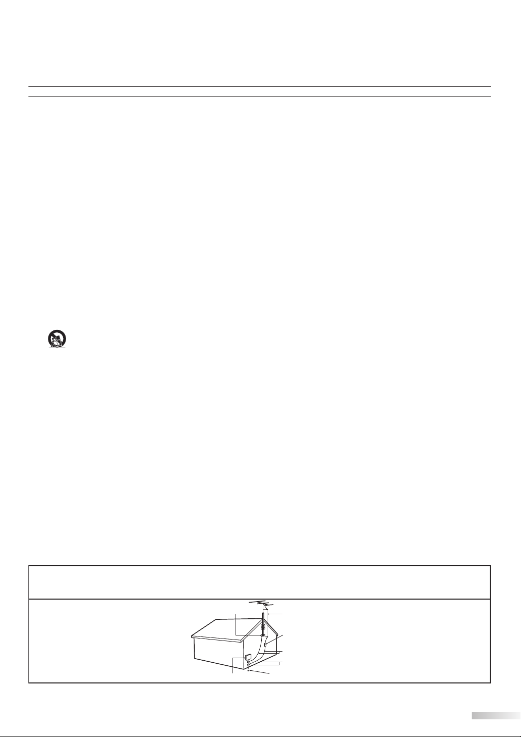
Example of Antenna Grounding as
per NEC - National Electric Code
GROUND CLAMP
ELECTRIC SERVICE EQUIPMENT POWER SERVICE GROUNDING ELECTRODE SYSTEM (NEC ART 250, PART H)
ANTENNA LEAD IN WIRE
ANTENNA DISCHARGE UNIT (NEC SECTION 810-20)
GROUNDING CONDUCTORS (NEC SECTION 810-21)
GROUND CLAMPS
3
EN
Page 4
NTRODUCTION
I
Precaution5
Precaution5
Do not place the unit on the furniture that is capable of being tilted by a child and an adult leaning, pulling, standing or climbing
on it. A falling unit can cause serious injury or even death.
FCC WARNING
This apparatus may generate or use radio frequency energy. Changes or modifications to this apparatus may cause
harmful interference unless the modifications are expressly approved in the manual. The user could lose the authority to
operate this apparatus if an unauthorized change or modification is made.
RADIO-TV INTERFERENCE
This apparatus has been tested and found to comply with the limits for a Class B digital device, pursuant to Part 15 of
the FCC Rules. These limits are designed to provide reasonable protection against harmful interference in a residential
installation. This apparatus generates, uses, and can radiate radio frequency energy and, if not installed and used in
accordance with the instructions, may cause harmful interference to radio communications. However, there is no
guarantee that interference will not occur in a particular installation. If this apparatus does cause harmful interference to
radio or television reception, which can be determined by turning the apparatus off and on, the user is encouraged to
try to correct the interference by one or more of the following measures:
1) Reorient or relocate the receiving antenna.
2) Increase the separation between the apparatus and receiver.
3) Connect the apparatus into an outlet on a circuit different from that to which the receiver is connected.
4) Consult the dealer or an experienced radio/TV technician for help.
This Class B digital apparatus complies with Canadian ICES-003.
Cet appareil numérique de la classe B est conforme à la norme NMB-003 du Canada.
This apparatus should not be placed in a built-in installation such as a bookcase or rack unless proper ventilation is provided.
Make sure to leave a space of 2.8 inches (7cm) or more around this apparatus.
Disconnect the mains plug to shut off when find trouble or not in use. The mains plug shall remain readily operable.
CAUTION: Danger of explosion if battery is incorrectly replaced. Replace only with the same or equivalent type.
WARNING: Batteries (battery pack or battery installed) shall not be exposed to excessive heat such as sunshine, fire or the like.
Like all LCD products, this set contains a lamp with Mercury, please dispose of according
to all Local, State and Federal laws. For the disposal or recycling information, contact:
www.mygreenelectronics.com or www.eiae.org
WARNING: To prevent injury, this apparatus must be securely attached to the floor/wall in accordance with the instructions.
TO AVOID THE HAZARDS OF ELECTRICAL SHOCK AND FIRE
Do not handle the AC power cord with wet hands.
•
Do not remove this unit cabinet. Touching parts inside the cabinet could result in electric shock and/or damage to this
•
unit. For service and adjustment inside the cabinet, call a qualified dealer or an authorized service center.
Do not pull on the AC power cord when disconnecting it from an AC outlet. Grasp it by the plug.
•
Do not put your fingers or objects into the unit.
•
LOCATION AND HANDLING
The openings should not be blocked by placing the unit on a bed, sofa, carpet, rug, or other similar surface.
•
Do not install the unit near or over a radiator or heat register.
•
Do not install the unit in direct sunlight, near strong magnetic fields, or in a place subject to dust or strong vibration.
•
Avoid a place with drastic temperature changes.
•
Install the unit in a horizontal and stable position. Do not place anything directly on top or bottom of the unit.
•
Depending on your external devices, noise or disturbance of the picture and/or sound may be generated if the unit is
placed too close to them. In this case, please ensure enough space between the external devices and the unit.
Depending on the environment, the temperature of this unit may increase slightly. This is not a malfunction.
•
NOTE ABOUT RECYCLING
This unit’s packaging materials are recyclable and can be reused.
•
Please dispose of any materials in accordance with your local recycling regulations.
Batteries should never be thrown away or incinerated but disposed of in accordance with your local
•
regulations concerning chemical wastes.
5
Trademark Information
HDMI, the HDMI logo and High-Definition Multimedia Interface are trademarks or registered trademarks of HDMI
•
Licensing LLC.
Manufactured under license from Dolby Laboratories. “Dolby” and the double-D symbol are trademarks of Dolby
•
Laboratories.
Products that have earned ENERGY STAR® are designed to protect the environment through superior energy efficiency.
•
4
EN
Page 5
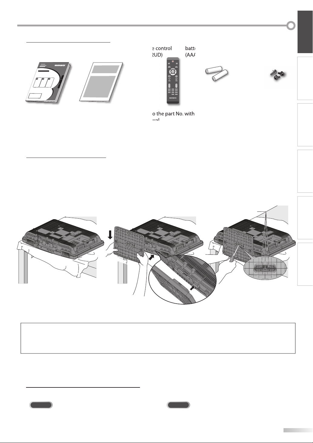
Supplied Accessories5
screw holes
user manual
(1EMN24239)
If you need to replace these accessories, please refer to the part No. with the illustrations and call our toll free
•
customer support line found on the cover of this manual.
Attaching the Stand
5
You must attach the stand to the unit to display upright. Be sure the front and rear of the stand match the proper direction.
Spread a thick and soft cloth over a
1
table.
Place the main unit face down onto it.
quick start guide
(1EMN24541)
2
remote control
(NF802UD)
Hang the hook under the bottom
of the main unit to the stand’s hole
(shown arrow
stand in the direction of the screen
(shown arrow
Make sure not to put the AC power
cord between the stand and the
unit.
), then slide down the
➀
).
➁
batteries
(AAA x 2)
Phillips pan screw for
attaching the stand x 3
(FPH34120)
AAA
AAA
Drive Phillips pan screws in the 3
3
threaded holes at the bottom of the
stand with a screwdriver tightly.
INTRODUCTION PREPARATION
WATCHING TV
OPTIONAL SETTING TROUBLESHOOTING
front sidefront side
To remove the stand from this unit
Unscrew the Phillips pan screws indicated by “➂”. Pull up the stand in the direction of the rear of the unit. Be careful not to drop the stand
when you remove it.
Note:
• When attaching the stand, ensure that all screws are tightly fastened. If the stand is not properly attached, it could cause the unit to fall,
resulting in injuries as well as damage to the unit.
• Make sure to use a table which can support the weight of this unit and is larger than this unit.
• Make sure the table is in a stable location.
Symbols Used in this Manual
5
The following is the description for the symbols used in this manual. Description refers to:
INFORMATION
TV
: Analog TV operation
• If neither symbol appears under the function heading, operation is applicable to both.
DTV
: Digital TV operation
5
EN
Page 6

NTRODUCTION
I
Features5
DTV/TV/CATV
•
You can use your remote control to select
-
channels which are broadcast in digital format and
conventional analog format. Also, cable subscribers
can access their cable TV channels.
Information Display (DTV only)
•
You can display the title, contents and other
-
information of the current DTV program on the TV
screen.
Autoprogram
•
This unit automatically scans and memorizes
-
channels available in your area, eliminating difficult
setup procedures.
Child Lock
•
This feature allows you to block children’s access to
-
inappropriate programs.
Closed Caption Decoder
•
Built-in closed caption decoder displays text for
-
closed caption supported programs.
MTS/SAP Tuner
•
Audio can be selected from the remote control.
-
Auto Shut Off Function
•
If there is no signal input from the antenna terminal
-
and no operation for 15 minutes, the unit will turn
off automatically.
Sleep Timer
•
This feature will automatically turn off the power of
-
the unit at a specific time.
Choices for On-screen Language
•
Select your on-screen language:
-
English, Spanish or French.
Stereo Sound Function
•
PLL Frequency Synthesized Tuning
•
Provides free and easy channel selection and lets
-
you tune directly to any channel using the number
buttons on the remote control.
Various Adjustment for Picture and Sound
•
Customizes image quality to suitable for your room,
-
and set the sound as your preference.
HDMI Input
•
Component Video Input
•
PC Input
•
S-video Input
•
AV Input
•
Digital Audio Output
•
Contents5
Important Safety Instructions . . . . . . . . . . . . . . . . . . . . . . . . . . .3
INTRODUCTION
Precaution . . . . . . . . . . . . . . . . . . . . . . . . . . . . . . . . . . . . . . . . . . . . . . 4
Trademark Information. . . . . . . . . . . . . . . . . . . . . . . . . . . . . . . . . . 4
Supplied Accessories . . . . . . . . . . . . . . . . . . . . . . . . . . . . . . . . . . . . 5
Attaching the Stand . . . . . . . . . . . . . . . . . . . . . . . . . . . . . . . . . . . . . 5
Symbols Used in this Manual . . . . . . . . . . . . . . . . . . . . . . . . . . . .5
Features . . . . . . . . . . . . . . . . . . . . . . . . . . . . . . . . . . . . . . . . . . . . . . . . . 6
Control Panel . . . . . . . . . . . . . . . . . . . . . . . . . . . . . . . . . . . . . . . . . . .7
Rear Panel . . . . . . . . . . . . . . . . . . . . . . . . . . . . . . . . . . . . . . . . . . . . . . . 7
Remote Control Function . . . . . . . . . . . . . . . . . . . . . . . . . . . . . . . 8
Installing the Batteries . . . . . . . . . . . . . . . . . . . . . . . . . . . . . . . . . . . 8
PREPARATION
Antenna Connection . . . . . . . . . . . . . . . . . . . . . . . . . . . . . . . . . . . .9
Connection to Cable Receiver or Satellite Box . . . . . . . . . . . 9
External Device Connection . . . . . . . . . . . . . . . . . . . . . . . . . . . .10
Plug In the AC Power Cord . . . . . . . . . . . . . . . . . . . . . . . . . . . . .13
Initial Setup . . . . . . . . . . . . . . . . . . . . . . . . . . . . . . . . . . . . . . . . . . . .14
WATCHING TV
Channel Selection . . . . . . . . . . . . . . . . . . . . . . . . . . . . . . . . . . . . . .15
Volume Adjustment . . . . . . . . . . . . . . . . . . . . . . . . . . . . . . . . . . . .15
Sleep Timer . . . . . . . . . . . . . . . . . . . . . . . . . . . . . . . . . . . . . . . . . . . .15
Still Mode . . . . . . . . . . . . . . . . . . . . . . . . . . . . . . . . . . . . . . . . . . . . . .16
Switching Each Input Mode . . . . . . . . . . . . . . . . . . . . . . . . . . . .16
Switching Audio Mode . . . . . . . . . . . . . . . . . . . . . . . . . . . . . . . . .16
TV Screen Information. . . . . . . . . . . . . . . . . . . . . . . . . . . . . . . . . .17
TV Screen Display Mode . . . . . . . . . . . . . . . . . . . . . . . . . . . . . . . .18
OPTIONAL SETTING
Main Menu . . . . . . . . . . . . . . . . . . . . . . . . . . . . . . . . . . . . . . . . . . . . .19
Autoprogram . . . . . . . . . . . . . . . . . . . . . . . . . . . . . . . . . . . . . . . . . .19
Channel List . . . . . . . . . . . . . . . . . . . . . . . . . . . . . . . . . . . . . . . . . . . .20
Add Channels . . . . . . . . . . . . . . . . . . . . . . . . . . . . . . . . . . . . . . . . . .20
Antenna Confirmation . . . . . . . . . . . . . . . . . . . . . . . . . . . . . . . . .21
Language Selection . . . . . . . . . . . . . . . . . . . . . . . . . . . . . . . . . . . .21
Picture Adjustment . . . . . . . . . . . . . . . . . . . . . . . . . . . . . . . . . . . .22
Sound Adjustment . . . . . . . . . . . . . . . . . . . . . . . . . . . . . . . . . . . . .23
Closed Caption . . . . . . . . . . . . . . . . . . . . . . . . . . . . . . . . . . . . . . . . .24
Child Lock . . . . . . . . . . . . . . . . . . . . . . . . . . . . . . . . . . . . . . . . . . . . . .27
PC Settings . . . . . . . . . . . . . . . . . . . . . . . . . . . . . . . . . . . . . . . . . . . . .30
Energy Saving Mode . . . . . . . . . . . . . . . . . . . . . . . . . . . . . . . . . . .31
Location . . . . . . . . . . . . . . . . . . . . . . . . . . . . . . . . . . . . . . . . . . . . . . .32
Current Software Info . . . . . . . . . . . . . . . . . . . . . . . . . . . . . . . . . .32
TROUBLESHOOTING
FAQ . . . . . . . . . . . . . . . . . . . . . . . . . . . . . . . . . . . . . . . . . . . . . . . . . . . .33
Troubleshooting Guide . . . . . . . . . . . . . . . . . . . . . . . . . . . . . . . .34
INFORMATION
Glossary . . . . . . . . . . . . . . . . . . . . . . . . . . . . . . . . . . . . . . . . . . . . . . . .36
Maintenance . . . . . . . . . . . . . . . . . . . . . . . . . . . . . . . . . . . . . . . . . . .36
Cable Channel Designations . . . . . . . . . . . . . . . . . . . . . . . . . . .37
General Specifications . . . . . . . . . . . . . . . . . . . . . . . . . . . . . . . . . .37
Electrical Specification . . . . . . . . . . . . . . . . . . . . . . . . . . . . . . . . .37
Other Specifications . . . . . . . . . . . . . . . . . . . . . . . . . . . . . . . . . . . .37
© 2009 Funai Electric Co., Ltd.
All rights reserved. No part of this manual may be reproduced, copied, transmitted, disseminated, transcribed, downloaded or stored in
any storage medium, in any form or for any purpose without the express prior written consent of Funai.
Furthermore, any unauthorized commercial distribution of this manual or any revision hereto is strictly prohibited.
Information in this document is subject to change without notice. Funai reserves the right to change the content herein without the
obligation to notify any person or organization of such changes.
with the design is a registered trademark of Funai Electric Co., Ltd and may not be used in any way without the express written
consent of Funai. All other trademarks used herein remain the exclusive property of their respective owners. Nothing contained in this
manual should be construed as granting, by implication or otherwise, any license or right to use any of the trademarks displayed herein.
Misuse of any trademarks or any other content in this manual is strictly prohibited. Funai shall aggressively enforce its intellectual property
rights to the fullest extent of the law.
Limited Warranty . . . . . . . . . . . . . . . . . . . . . . . . . . . . . . . . . . . . . . .38
6
EN
Page 7
INTRODUCTION PREPARATION
HDMI 2
HEAD PHONE
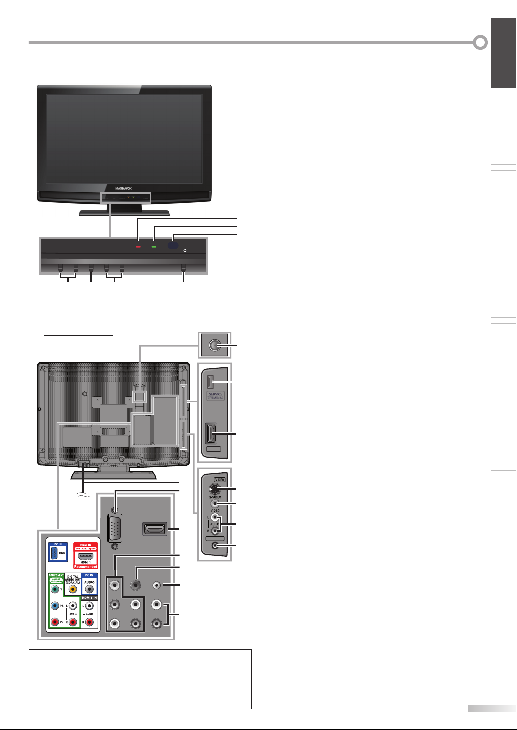
Control Panel5
1. yy POWER (p. 14)
Press to turn the unit on and off.
+ /
-
+ /
-
(p. 15 / p. 16)
(p. 15)
+) / down (
+) / left
-
)
WATCHING TV
OPTIONAL SETTING TROUBLESHOOTING
2. CHANNEL
Press to select channels or move up (
through the main menu items.
3. MENU (p. 19)
Press to display the main menu.
4. VOLUME
Press to adjust the volume or move right (
-
) through the main menu items.
(
5. STAND BY indicator
Lights up red when power is off.
6. POWER ON indicator
5
6
STAND BY
-
VOLUME
+
MENU
-
CHANNEL
POWER ON
+
POWER
7
Lights up green when power is on.
7. infrared sensor window
Receives infrared rays transmitted from the remote
control.
24
13
Rear Panel5
HDMI 2
14
15
16
Note:
service terminal (service use only)
*
Use this terminal only when a software update is necessary.
Do not connect any device to this terminal such as; digital
camera, keyboard, mouse, etc. For more information,
please visit at www.magnavox.com/support
HEAD PHONE
17
18
19
20
8. antenna input jack (p. 9)
8
coaxial cable connection for your antenna or cable
RF
TV signal.
9. HDMI 2 input jack (p. 9 / p. 10)
HDMI connection for HDMI device.
*
10. S-video input jack (p. 11)
S-video cable connection for an external device.
11. video input jack (p. 12)
RCA video cable connection for an external device.
12. audio input jack (p. 9 / p. 10 / p. 11 / p. 12)
9
RCA audio cable connection for an external device.
13. headphone jack
Headphone connection for personal listening.
14. AC power cord (p. 13)
10
11
Connect to a standard AC outlet to supply power to
this unit.
15. PC input jack (p. 13)
VGA cable connection for PC.
12
16. HDMI 1 input jack (p. 9 / p. 10)
HDMI connection for HDMI or DVI device.
13
component video and audio input jack
17.
RCA component video cable and RCA audio cable
connection for an external device.
18. digital audio output jack (p. 12)
Coaxial digital cable connection for a decoder or an
audio receiver.
19. audio input jack for PC connection (p. 13)
Mini-plug audio cable connection for PC.
20. audio input jack for HDMI 1 (p. 10)
RCA audio cable connection for a DVI device.
(For HDMI 1 input jack only)
INFORMATION
(p. 9 / p. 11)
7
EN
Page 8
NTRODUCTION
6
AAA
AAA
I
Remote Control Function5
1
2
3
4
5
6
7
8
9
10
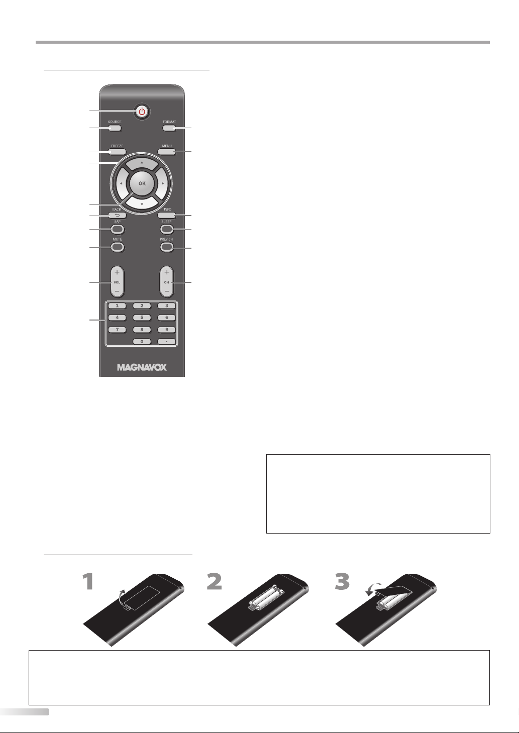
1. yy (power) (p. 14)
Press to turn the unit on and off.
2. SOURCE (p. 16)
Press to access connected external devices like a
BD/DVD recorder.
3. FREEZE (p. 16)
Press to pause screen image.
4.
s
/ B / K / L (p. 14)
Press to move left / right / up / down through the
items.
5. OK (p. 14)
Press to decide the command of setting when the
main menu is displayed.
6. BACK (p. 17)
Press to return to the previous menu operation.
11
12
13
14
15
1
7. SAP (p. 16)
Digital mode (DTV)
• Press to select the audio language.
Analog mode (TV)
• Press to select the audio mode.
8. MUTE (p. 15)
Press to turn the sound on and off.
9. VOL + /
Press to adjust the volume.
10. Number buttons (p. 15)
Press to select channels.
• (dot)
• Press to shift the subchannel from the main channel.
11. FORMAT (p. 18)
Press to select aspect ratio available for the TV screen.
12. MENU (p. 19)
Press to display the main menu.
13. INFO (p. 17)
Digital mode (DTV)
• Press to display the channel information, signal type
Analog mode (TV)
• Press to display the channel number, signal type and
External input mode
• Press to display the external input modes, signal type
14. SLEEP (p. 15)
Press to activate the sleep timer.
15. PREV CH (p. 15)
Press to return to the previous channel.
16. CH + /
Press to select channels and the
external input modes.
-
(p. 15)
and TV setting.
TV setting.
and TV setting.
-
(p. 15 / p. 16)
When using a universal remote control
to operate this unit.
• Make sure the component code on your universal
remote control is set to our brand.
Refer to the manual accompanying your remote
control for more details.
Installing the Batteries
5
Install the batteries (AAA x 2) matching the polarity indicated inside battery compartment of the remote control.
AAA
AAA
AAA
AAA
Battery Precautions:
• Be sure to follow the correct polarity as indicated in the battery compartment. Reversed batteries may cause damage to the device.
• Do not mix different types of batteries together (e.g., Alkaline and Carbon-Zinc, or rechargeable batteries like ni-cad, ni-mh, etc) or
old batteries with fresh ones.
• If the device is not to be used for a long period of time, remove the batteries to prevent damage or injury from possible battery leakage.
• Do not try to recharge batteries; they can overheat and rupture.
8
EN
Page 9
REPARATION
HDMI 2
(green)
(red)
(blue)
(green)
(red)
(blue)
P
No supplied cables are used in this connection:
Please purchase the necessary cables at your local store.
High Speed HDMI cable (also known as HDMI category 2 cable) is recommended for the better compatibility.
Before you connect...
Be sure your antenna or other device is connected properly before plugging in the AC power cord.
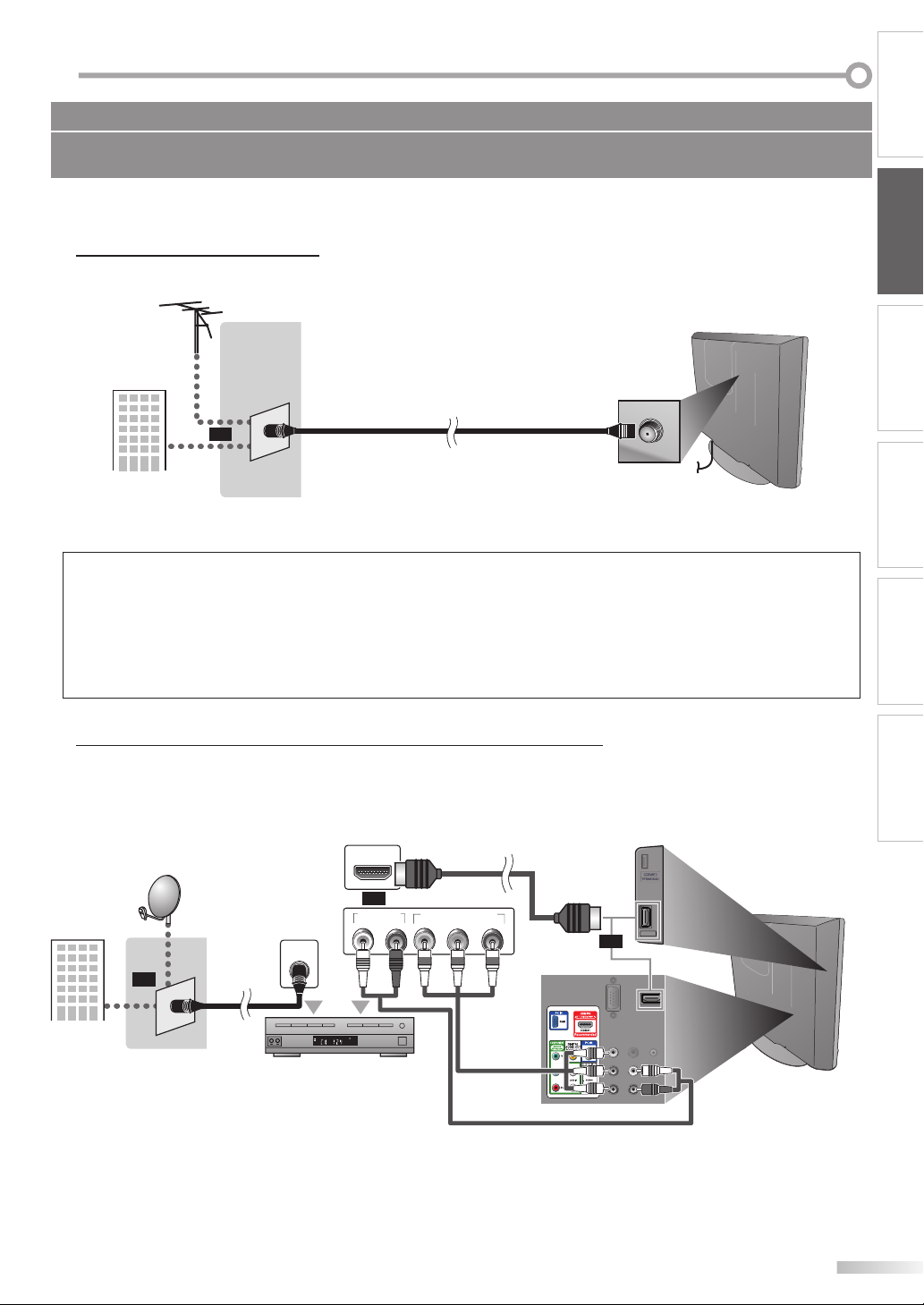
Antenna Connection
5
Connect the RF coaxial cable on your home outlet to the antenna input jack of this unit.
e.g.)
VHF / UHF
antenna
RF coaxial cable
or
or
cable TV signal
Once connections are completed, turn on the unit and begin initial setup. Channel scanning is necessary for the unit
*
rear of this unit
to memorize all available channels in your area. (Refer to “Initial Setup” on page 14.)
Note:
• If you have any question about the DTV’s antenna, visit www.antennaweb.org for further information.
• Depending on your antenna system, you may need different types of combiners (mixers) or separators (splitters). Contact your local
electronics store for these items.
• For your safety and to avoid damage to this unit, please unplug the RF coaxial cable from the antenna input jack before moving the unit.
• If you use an antenna to receive analog TV, it should also work for DTV reception. Outdoor or attic antennas will be more effective than
settop versions.
• To switch your reception source easily between antenna and cable, install an antenna selector.
• If you connect to the cable system directly, contact the CATV installer.
INTRODUCTION
PREPARATION
WATCHING TV
OPTIONAL SETTING TROUBLESHOOTING
5
cable TV signal
including PPV
Connection to Cable Receiver or Satellite Box
Use an HDMI or an RCA component video cable to connect the HDMI or the component video input jack of the unit to the
HDMI or the component video output jack of the cable receiver / satellite box.
If you connect to the unit’s COMPONENT video input jack, connect an RCA audio cable to the audio L/R jack of
COMPONENT accordingly.
RL
(green)(green)
HDMI cable
COMPONENT VIDEO OUT
(blue)(blue)
Pr/CrPb/CbY
(red)(red)
(green)
(green)
(blue)
(blue)
(red)
(red)
rear of this unit
HDMI 2
or
e.g.)
satellite dish
ANT IN
or
You can also connect this unit to the cable receiver or satellite box other than the HDMI or the component video
*
RF coaxial
cable
cable receiver / satellite box
RCA component video cable
HDMI OUT
or
AUDIO OUT
STEREO
PCM
and RCA audio cable
output jack because they might have different output jacks.
Required cables and connecting methods of the cable receiver / satellite box, or the availability channel for the
*
clear QAM may differ depending on the cable / satellite provider. For more information, please contact your cable /
satellite provider.
INFORMATION
9
EN
Page 10
REPARATION
HDMI 2
P
No supplied cables are used in this connection:
Please purchase the necessary cables at your local store.
High Speed HDMI cable (also known as HDMI category 2 cable) is recommended for the better compatibility.
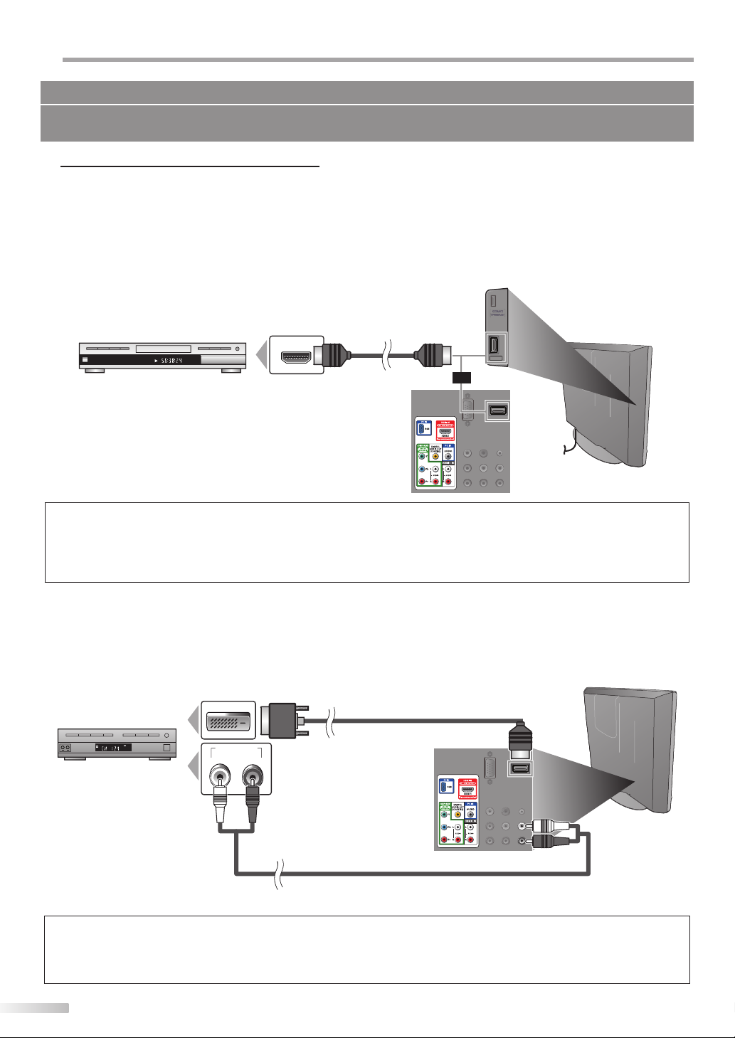
External Device Connection
5
[HDMI Connection]
HDMI connection offers the highest picture quality.
HDMI (High-Definition Multimedia Interface) transports high definition video and multi-channel digital audio
through a single cable.
e.g.)
TITLE 5
CHAPTER 15
REPEAT A-B
BD/DVD recorder
with the HDMI output jack
HDMI OUT
HDMI cable
HDMI 2
or
rear of this unit
Note:
• This unit accepts 480i / 480p / 720p / 1080i video signals, and 32kHz / 44.1kHz / 48kHz audio signals.
• This unit accepts only 2 channel audio signal (LPCM).
• You need to select “PCM” for the digital audio output of the device you connected or check the HDMI audio setting.
There may be no audio output if you select “Bitstream”, etc.
• This unit only accepts signals in compliance with EIA861.
[HDMI-DVI Connection]
Use an HDMI-DVI conversion cable to connect the unit to external video devices equipped with DVI output jack.
e.g.)
STEREO
PCM
cable receiver or satellite box
with the DVI output jack
DVI OUT
AUDIO OUT
HDMI-DVI conversion cable
To HDMI1
input jack only
RL
rear of this unit
RCA audio cable
Note:
• This unit accepts 480i / 480p / 720p / 1080i video signals.
• HDMI-DVI connection requires separate RCA audio connection as well.
• Audio signals are converted from digital to analog for this connection.
• DVI does not display 480i image that is not in compliance with EIA/CEA-861/861B.
10
EN
Page 11
No supplied cables are used in this connection:
(green)
(blue)
(red)
Please purchase the necessary cables at your local store.
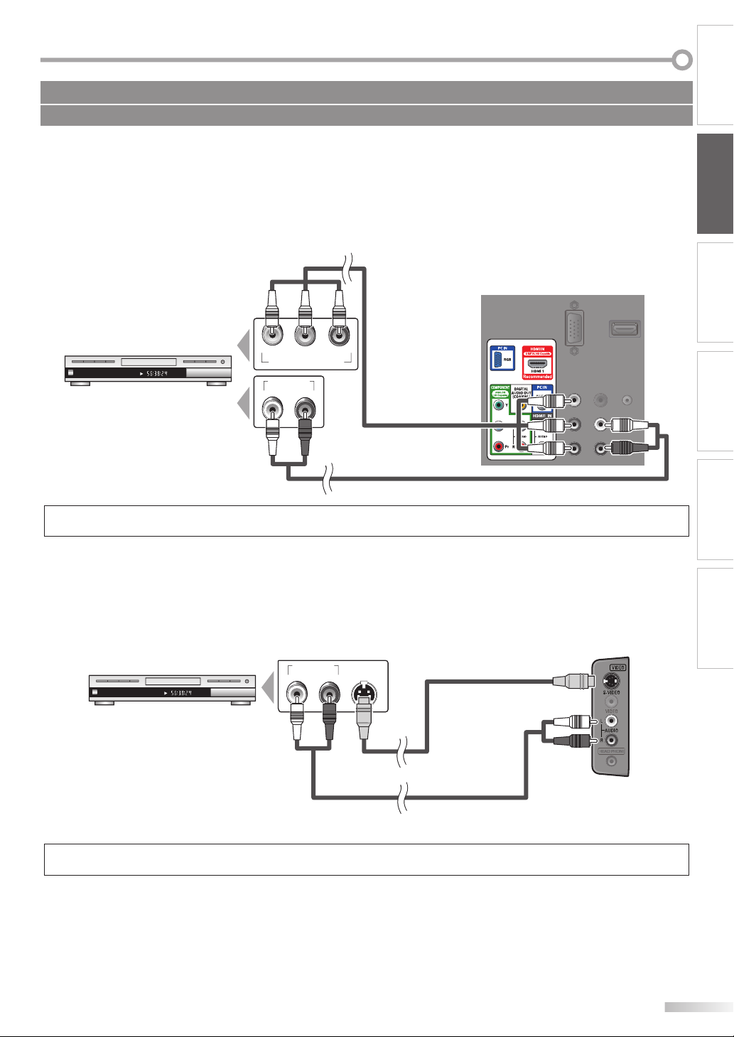
[Component Video Connection]
RCA component video connection offers better picture quality for video devices connected to the unit.
If you connect to the unit’s COMPONENT video input jack, connect an RCA audio cable to the audio L/R jack of
COMPONENT accordingly.
INTRODUCTION
PREPARATION
e.g.)
rear of this unit
(red)(blue)(green)
Pr/CrPb/CbY
RL
(green)
(green)
(blue)
(blue)
RCA component
video cable
(red)
(red)
TITLE 5
CHAPTER 15
REPEAT A-B
BD/DVD recorder with
the component video output jack
COMPONENT VIDEO OUT
AUDIO OUT
RCA audio cable
Note:
• This unit accepts 480i / 480p / 720p / 1080i video signals.
[S-video Connection]
S-video connection offers good picture quality for video devices connected to the unit.
If you connect to the unit’s S-video input jack, connect an RCA audio cable to the audio L/R jack of VIDEO accordingly.
e.g.)
TITLE 5
CHAPTER 15
REPEAT A-B
AUDIO OUT
S-V I D EO
OUT
RL
S-video cable
side of this unit
WATCHING TV
OPTIONAL SETTING TROUBLESHOOTING
INFORMATION
BD/DVD recorder with
the S-video output jack
RCA audio cable
Note:
• If you connect to the S-video input jack and the video input jack at the same time, the S-video connection will have priority.
11
EN
Page 12
REPARATION
P
No supplied cables are used in this connection:
Please purchase the necessary cables at your local store.
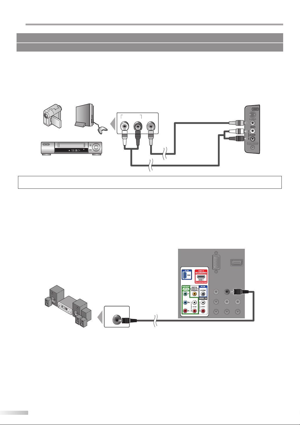
[Video Connection]
RCA video connection offers standard picture quality for video devices connected to the unit.
If you connect to the unit’s video input jack, connect an RCA audio cable to the audio L/R jack of VIDEO accordingly.
When the audio jack of the video device is monaural, connect an RCA audio cable to the audio L input jack.
e.g.)
camcorder
STEREO
video game
VCR
STAND-BY
AUDIO OUT
VIDEO
RL
OUT
RCA audio cable
RCA video cable
side of this unit
Note:
• If you connect to the S-video input jack and the video input jack at the same time, the S-video connection will have priority.
[Audio Output Connection (for digital broadcasting only)]
If you connect this unit to an external digital audio device, you can enjoy multi-channel audio like 5.1ch digital
broadcasting sound.
Use a digital audio coaxial cable to connect the unit to external digital audio devices.
e.g.)
rear of this unit
12
EN
Dolby Digital
decoder
DIGITAL AUDIO
COAXIAL IN
digital audio coaxial cable
Page 13

No supplied cables are used in this connection:
Please purchase the necessary cables at your local store.
[PC Connection]
This unit is equipped with a PC input jack. If you connect this unit to your PC, you can use this unit as a PC monitor.
Use an VGA cable for this connection and it requires stereo mini plug audio cable as well.
INTRODUCTION
PREPARATION
e.g.)
VGA cable should be
with ferrite core.
personal computer
The following signals can be displayed:
Format Resolution Refresh rate Format Resolution Refresh rate
VGA 640 x 480 60Hz
SVGA 800 x 600 60Hz
XGA 1,024 x 768 60Hz
Other formats or non-standard signals will not be displayed correctly.
stereo mini-plug audio cable
VGA cable
1,280 x 768 60Hz
WXGA
1,360 x 768 60Hz
rear of this unit
Note:
• Please purchase the VGA cable that has a ferrite core.
• The following operations may reduce noise.
- Attach a ferrite core to the AC power cord of your PC.
- Unplug the AC power cord and use the built-in battery of your PC.
WATCHING TV
OPTIONAL SETTING TROUBLESHOOTING
INFORMATION
Plug In the AC Power Cord
5
Make sure that the AC power cord must be plugged to an AC outlet after all the necessary connection is completed.
rear of this unit
AC power cord
AC outlet
Caution:
• Do not connect the AC power cord to a power supply outside the indicated voltage of this unit (AC 120V).
Connecting the AC power cord to a power supply outside of this range may result in fire or electrical shocks.
Note:
• Each time you plugged in the AC power cord, any operations will not be performed for a few seconds. This is not a malfunction.
13
EN
Page 14

REPARATION
y
P
These operations are accessible by remote control. Some may also be accessible by controls on the main unit.
Initial Setup
5
This section will guide you through the unit’s initial setting which includes
selecting a language for your on-screen menu and autoprogram, which
automatically scans and memorizes viewable channels.
Before you begin:
Make sure if the unit is connected to antenna or cables.
After making all the necessary connections,
1
press [
y (power)] to turn on the unit.
This operation may take a few moments.
•
Use [Cursor K / L] to select the on-screen language
2
from the choices on the right side of the TV screen.
(English / Español / Français)
Initial Setup
Initial Setup
Select the language for setup display.
Elija el idioma de ajuste.
Sélectionner langue écran config.
English
Español
Français
Use [Cursor s / B] to select the desired location setting,
4
then press [OK].
Initial Setup
Initial Setup
Select “Retail” or “Home” for your location.
Retail
Select ”Retail”, the unit will be set up with predefined
•
Select
setting for retail displays. In this setting, the power
consumption may possibly exceed the limited
requirement of the ENERGY STAR® qualification.
Select ”Home”, the unit is set to maximize the energy
•
efficiency for home setting and it can be adjusted
through a choice of picture and sound quality
according to your preference.
When the initial setup is completed, the lowest
•
memorized channel with the confirmation message
of the location setting will be displayed on the TV
screen.
Select Skip
•
“Initial Setup” menu on step 3 will be displayed in the
OK
OK
selected language after you press [OK].
Use [Cursor K / L] to select “Antenna” for TV channels
3
or “Cable” for CATV channels, then press [OK].
Initial Setup
Initial Setup
Make sure the antenna is connected to ''ANT. IN'' jack.
Select your signal source.
Antenna
Or
Cable
OK
Select Skip
“Autoprogram” will begin.
•
Initial Setup
Initial Setup
Now the system is scanning for channels, please wait.
Auto programming will take up to 20 minutes to complete.
0%
Analog channels 0ch
Digital channels 0ch
MENU
Note:
• If you connect the cable system directly, contact the CATV
installer.
• If you press [yy (power)] or [MENU] during autoprogram,
this setting will be canceled.
• The initial autoprogram function can be executed for
either “Antenna” or “Cable” only once. When you change
the connection (Antenna / Cable), set autoprogram again.
(Refer to page 19.)
• If there is no signal input from the antenna terminal and
no operation for several seconds after you turn on the unit,
“Helpful Hints” appears. Follow the instructions listed on
Antenna
Cable
Skip
ANT.IN
MENUBACK
BackOK
the TV screen.
Initial Setup
Initial Setup
No channel is registered.
Try Autoprogram again?
Verify that you have a cable connected to the "ANT. IN" jack on the
back of the TV, the channel installation process searches this
connection. If you are using a cable or satellite box, please confirm
the input which you have connected the box and press "SOURCE"
key on the remote control to select the appropriate source input.
OK
Select Skip
OK
• You must set ”Home” in step 4. Otherwise, the settings
of picture and sound quality you adjusted will not be
memorized after you turn off the unit.
After an initial setup is completed...
MENU
Skip
If you want to scan the channels automatically again,
•
refer to “Autoprogram” on page 19.
•
You can add the desired channels unmemorized by
“Autoprogram”. Refer to “Add Channels” on page 20.
If you want to change the other language from the
•
one you chose, refer to “Language Selection” on
page 21.
•
If you want to change the mode for location setting,
refer to “Location” on page 32.
Home
OK
OK
Retry
Later
MENU
14
EN
Page 15

ATCHING TV
W
Channel Selection
5
Select channels by using [CH + / -] or [the Number buttons].
To select the memorized channels, use [CH + / -] or
•
[the Number buttons].
•
To select the non-memorized channels, use
[the Number buttons].
To Use [the Number buttons]
TV
-
When selecting analog channel 11
DTV
-
When selecting digital channel 11.1
Be sure to press [•] before
entering the subchannel number.
Volume Adjustment
5
This section describes how to adjust the volume. The mute function, which
turns the sound off and on, is also described.
Use [VOL + / -] to adjust the audio volume.
Volume 30
The volume bar will be displayed at the bottom of the
TV screen when adjusting the volume.
•
The volume bar will automatically disappear in a few
seconds.
Press [MUTE] to turn off and on the sound.
INTRODUCTION
PREPARATION WATCHING TV
OPTIONAL SETTING TROUBLESHOOTING
Press [PREV CH] to return to the previously viewed
•
channel.
About digital TV broadcasting:
With its high definition broadcast, digital broadcasting
far surpasses analog broadcasting in both its picture
and sound quality. Not all digital TV broadcasts are high
definition (HD). To confirm whether your watching TV
program is in HD, refer to the program guide, contact
your cable / satellite provider or local TV stations.
NTSC
(analog mode)
(Soccer)
CH4
(Soccer)
CH4
(Soccer)
CH4
(Soccer)
CH4
Air time
18:00
18:30
19:00
19:30
20:00
(Soccer)
CH4-1
main channel
CH4-1
main channel
can be changed by using [CH + / -].
(digital mode)
CH4-1
main channel
CH4-2
CH4-1
main channel
(Soccer)
ATSC
(Soccer)
(News)
(Soccer)
CH4-3
CH4-2
subchannel
(Tennis)
subchannelsubchannel
(News)
What is the subchannel?
By using high compression technology, digital
broadcasting offers a service that enables multiple
signals to send simultaneously.
Therefore, you can select more than one program per
main channel since digital broadcasting technology
distinguishes between multiple channels broadcast by
a single network.
Note:
• “No Signal” will appear on the TV screen after the
subchannel broadcast is over.
• “Audio only program“ message will appear on the TV
screen, when you receive only sound signal.
Mute
“Mute” is displayed on the TV screen for a few seconds.
Press [MUTE] again or [VOL + / -] to recover the
original volume.
Sleep Timer
5
The sleep timer can be set to automatically turn off the unit after an
incremental period of time.
Press [SLEEP] to set the sleep timer.
1
Sleep
Off
Sleep timer display appears on the TV screen.
Press [SLEEP] repeatedly to change the amount of time
2
until shut off.
120min.
Sleep
You can set your unit to turn off after a set period of
time (from 30 to 120 minutes).
Each press of [SLEEP] will increase the time by 30
•
minutes.
After setup, the sleep timer display can be called up
•
for checking by pressing [SLEEP].
To cancel the sleep timer
Press [SLEEP] repeatedly until “Sleep Off” is displayed
on the TV screen.
Note:
• The sleep timer display will automatically disappear in a
few seconds.
• When you disconnect the unit from the AC outlet or when
a power failure occurs, the sleep timer setting will be
canceled.
INFORMATION
15
EN
Page 16

ATCHING TV
y
W
Still Mode
5
You can pause the image shown on the TV screen.
Press
5
You can easily switch with the remote control to the DTV (ATSC) and TV
(NTSC) or to access external devices when they are connected to the unit.
[FREEZE] to pause the image shown on the TV
screen.
FREEZE
The sound output will not be paused.
•
If no signal is detected or protected signal is received
•
during still mode, the image remains paused and the
sound output will be muted.
The still function will be released after 5 minutes.
•
To cancel still mode, press any button except
[
y (power)].
Switching Each Input Mode
Press [SOURCE] or [CH +] repeatedly to cycle through
the input modes.
Switching Audio Mode
5
This section describes how to switch the audio in the analog mode and how
to switch the audio language in the digital mode.
TV
Press [SAP] to display the currently selected audio
mode. While receiving an MTS broadcast, press
repeatedly to cycle through the available audio
channel.
11
When all audio are available
When stereo and monaural audio are available
When SAP and monaural audio are available
When only monaural audio is available
STEREO : Outputs stereo-audio
SAP : Outputs second audio program
MONO : Outputs mono-audio
SAP / STEREO SAP / MONO
SAP / STEREO
MONO / STEREO MONO / STEREO
SAP / MONO SAP / MONO
(cannot be switched)
SAP / STEREO
MONO
DTV/TV channel
Video
Component
HDMI1
Pressing [CH -] reverses the direction of the input
•
modes.
HDMI2
PC
DTV
Press [SAP] to display the currently selected language
1
and the number of available languages.
11.1
Press [SAP] repeatedly to cycle through the available
2
audio languages.
Available languages differ depending on the
•
broadcast. “Other” is displayed when the audio
language cannot be acquired, or the acquired
languages are other than English, Spanish or French.
English 1/3
Note:
• [SAP] does not control external audio devices.
• The information display will automatically disappear in a
few seconds.
16
EN
Page 17

TV Screen Information
5
You can display the currently selected channel or other information such as
the audio mode on the TV screen.
TV
In the analog mode, the current channel number and the audio mode are
displayed.
DTV
In the digital mode, the detailed broadcasting information for the current
channel such as program title, program guides are displayed.
INTRODUCTION
PREPARATION WATCHING TV
Press [INFO].
11
SAP / STEREO
480i
480i
The current channel number, audio mode, type of
•
resolutions for video signal, TV aspect ratio, CC and
TV program rating are displayed on the top-right
corner of the TV screen.
To clear the display, press [INFO] again. You can also
•
press [BACK].
SD
SD
TV-PG DLSV
4:3
4:3
CC
CC
Press [INFO] to display the details of the currently
selected program.
Broadcasting information
The following information is displayed.
1 2
A Day of Memories
A Day of Memories
A quarter-century ago,which may now qualify as the
good old days of newspapering,run-of-paper sales
accounted for 80 percent of the industry's advertising
revenues.Department stores and supermarket were
TV: TV-14
1 program title
2 program guide
(The program guide added to broadcasting
information is displayed to a maximum of 4 lines.)
3 broadcast station
4 channel number
5 audio language
(Refer to “Switching Audio Mode” on page 16.)
6 effective scanning lines and scan mode
7 digital TV format
8 program aspect ratio
9 CC (not available if closed caption is set to “Off”)
10 child lock rating
34
KABC
KABC
English 1/2
1080i
1080i
Rating
11.1
OPTIONAL SETTING TROUBLESHOOTING
5
16:9HDHD
16:9
6, 7, 8
CC
CC
9
INFORMATION
Note:
• When the program guide consists of more than 4 lines, use
[Cursor K/ L] to scroll.
• “No description provided.” is displayed when the program
guide is not provided.
• While the program guide is displayed, the closed caption
function is interrupted.
• In external input mode, the following screen is displayed;
e.g.) When an external device is connected to VIDEO input
jack.
Video
480iSDSD
480i
TV-PG DLSV
• The information display will automatically disappear in
1 minute.
CC
CC
17
EN
Page 18

ATCHING TV
W
TV Screen Display Mode
5
4 types of display modes can be selected when the broadcasting station
is sending 4:3 or 16:9 video signal. And 3 types of display modes can be
selected for PC input signal.
Press [FORMAT] repeatedly to switch the TV aspect
ratio.
For 4:3 video signal
For 16:9 video signal
Normal
Wide
Normal
Display a 4:3 picture at its original size. Sidebars appear
on both edges of the screen.
16:9
Display a 4:3 picture at a 16:9 size; the picture is
stretched horizontally to fill the screen.
Movie Expand
Display a 4:3 picture at a 16:9 size; the picture is
stretched horizontally and vertically to fill the screen.
This crops out the top and bottom of the picture.
Wide
Display the picture with its center at the original size
and the edges stretched horizontally.
16:9
Movie Expand
Normal
Wide
Normal
Display a 16:9 picture at its original size.
Zoom
Display a 16:9 picture at its maximum size without
changing its horizontal and vertical ratio.
Movie Expand
Display a vertically stretched picture.
Wide
Display a horizontally stretched picture.
For PC input signal
Zoom
Movie Expand
18
EN
Normal Full
Normal
Display a proportionately stretched picture. Sidebars
appear on both edges of the screen.
Full
Display a picture that is stretched out of proportion to
fill the screen.
Dot By Dot
Display a picture in its original size.
Dot By Dot
Page 19

PTIONAL SETTING
O
Main Menu
5
This section describes the overview of the main menu displayed when you
press [MENU]. For more details, see the reference page for each item.
The main menu consists of the function setting items below.
Press [MENU].
Autoprogram
5
If you switch wires (e.g., between antenna and CATV) or if you move the
unit to a different area after the initial setting, or if you restore the DTV
channel you deleted, you will need to perform autoprogram.
Before you begin: Make sure if the unit is connected to antenna or cables.
Press [MENU] to display the main menu.
1
INTRODUCTION
PREPARATION
PICTURE
Smart Picture
SOUND
SETUP
FEATURES
LANGUAGE
Brightness
Contrast
Color
Tint
Sharpness
Color Temperature
Personal
Normal
PICTURE
You can adjust the picture quality.
(Refer to “Picture Adjustment” on page 22.)
SOUND
You can adjust the sound quality.
(Refer to “Sound Adjustment” on page 23.)
SETUP
•
You can automatically scan the viewable channels.
(Refer to “Autoprogram” on page 19.)
•
You can skip the undesired channels when selecting
+ /
-
the channels using [CH
].
(Refer to “Channel List” on page 20.)
You can add the channels that were not scanned by
•
the autoprogram.
(Refer to “Add Channels” on page 20.)
FEATURES
You can change the display format for closed
•
caption, which displays the dialogue of a TV program
or other information across the TV screen.
(Refer to “Closed Caption” on page 24.)
You can set the viewing limitations.
•
(Refer to ‘‘Child Lock” on page 27.)
You can adjust the position, stability and clarity of the
•
PC screen.
(Refer to “PC Settings” on page 30.)
You can select the energy saving mode.
•
(Refer to “Energy Saving Mode” on page 31.)
When you adjust the desired “PICTURE” and
•
“SOUND” mode, you must switch the setting from
“Retail” to “Home”. (Refer to “Location” on page 32.)
•
You can confirm the version of the software currently
used in this unit.
(Refer to ”Current Software Info” on page 32.)
LANGUAGE
You can change the language (English, Spanish,
French) displayed on the main menu.
(Refer to “Language Selection” on page 21.)
30
60
36
0
0
Use [Cursor K / L] to select “SETUP” , then press [OK].
2
PICTURE
Autoprogram
Channel List
SOUND
Add Channels
SETUP
Antenna
FEATURES
LANGUAGE
Use [Cursor K / L] to select “Autoprogram”, then press
3
WATCHING TV
OPTIONAL SETTING
[OK].
PICTURE
Autoprogram
Channel List
SOUND
Add Channels
SETUP
Antenna
FEATURES
LANGUAGE
TROUBLESHOOTING
Use [Cursor K / L] to select an appropriate option, then
press [OK].
When aerial antenna is connected, select “Antenna”.
•
When connected to CATV, select “Cable”.
•
“Autoprogram” will begin.
•
When the scanning and memorizing are completed,
•
the lowest memorized channel will be displayed.
Note:
• After setting “Autoprogram”, using [CH + / -] on the remote
control skips unavailable programs automatically.
• If you connect the cable system directly, contact the CATV
installer.
• If you press [yy (power)] or [MENU] during autoprogram,
the setting will be canceled.
• Even if “Autoprogram“ is completed, the channel setting
will be lost if the AC power Code is unplugged before
turning off the unit by pressing [yy (power)].
• The PIN Code will be required once you set a PIN Code in
the “Child Lock” (Refer to page 27).
• If you want to change your PIN Code, follow the instruction
of “Change PIN” (Refer to page 30.)
PICTURE
Autoprogram will rescan all channels.
SOUND
Autoprogramming will take up to 20 minutes
SETUP
to complete.
FEATURES
Select your signal source.
LANGUAGE
Antenna
Or
Cable
Now the system is scanning for channels, please wait.
Now the system is scanning for channels, please wait.
Auto programming will take up to 20 minutes to complete.
Auto programming will take up to 20 minutes to complete.
75%
75%
Analog channels 10 ch
Analog channels 10 ch
MENU
MENU
Exit
Exit
Back
Antenna
Cable
ANT.IN
6 chDigital channels
6 chDigital channels
INFORMATION
19
EN
Page 20

PTIONAL SETTING
O
Channel List
5
The channels selected here can be skipped when selecting the channels
using [CH + / -].
Those channels can still be selected with [the Number buttons].
Add Channels
5
This function lets you add the channels that were not added by the
autoprogram due to the receptible condition at the initial setting.
Press [MENU] to display the main menu.
1
Use [Cursor K / L] to select “SETUP”, then press [OK].
2
PICTURE
Autoprogram
Channel List
SOUND
Add Channels
SETUP
Antenna
FEATURES
LANGUAGE
Use [Cursor K / L] to select “Channel List”, then press
3
[OK].
PICTURE
Autoprogram
Channel List
SOUND
Add Channels
SETUP
Antenna
FEATURES
LANGUAGE
Use [Cursor K / L] to select the channel you want to
4
remove, then press [OK].
Press [MENU] to display the main menu.
1
Use [Cursor K / L] to select “SETUP”, then press [OK].
2
PICTURE
Autoprogram
Channel List
SOUND
Add Channels
SETUP
Antenna
FEATURES
LANGUAGE
Use [Cursor K / L] to select “Add Channels”, then press
3
[OK].
Autoprogram
PICTURE
Channel List
SOUND
Add Channels
SETUP
Antenna
FEATURES
LANGUAGE
Use [the Number buttons] to enter the number of the
4
channel you want to add, then press [OK].
The channel display for the removed channel
•
darkens. You will not be able to select the channel
again using [CH
To reactivate a removed channel, use [Cursor K / L] and
•
press [OK]. The registered channels are highlighted.
When you remove a main channel, its subchannels
•
are removed as well.
Note:
• The channel with the “DTV” indicated on the display is
ATSC. Otherwise the channel is NTSC.
Press [MENU] to exit.
5
20
EN
+ /
PICTURE
SOUND
SETUP
FEATURES
LANGUAGE
Highlight channels for Ch Up/Down key
selection.
OK
Ch Select Watch/Skip
DTV 11.1
DTV
DTV
BACK
Back
11.2
11.3
PICTURE
SOUND
For analog channels, select a channel to be
added using number keys.
SETUP
For digital channels, you must perform
FEATURES
Autoprogram function.
LANGUAGE
BACK
Ch Change
11
Add channels
Back
-
].
Press [MENU] to exit.
5
Note:
• If setup completes successfully,
“Added to the channel list” is displayed.
• If external input is used, it is not possible to register the
channel and “Unavailable” will be displayed on the TV
screen.
• By using [CH + / -], you can select the memorized
channels only.
Page 21

Antenna Confirmation
5
DTV
This function lets you check the digital signal strength of each channel.
Press [MENU] to display the main menu.
1
Language Selection
5
You can choose English, Spanish, or French as your on-screen language.
Press [MENU] to display the main menu.
1
INTRODUCTION
PREPARATION
Use [Cursor K / L] to select “SETUP”, then press [OK].
2
PICTURE
Autoprogram
Channel List
SOUND
Add Channels
SETUP
Antenna
FEATURES
LANGUAGE
Use [Cursor K / L] to select “Antenna”, then press [OK].
3
PICTURE
Autoprogram
Channel List
SOUND
Add Channels
SETUP
Antenna
FEATURES
LANGUAGE
Use [the Number buttons] or [CH
4
+ / -] to select the
channel for which you want to check the digital signal
strength.
11.1
Use [Cursor K / L] to select “LANGUAGE”, then press
2
[OK].
PICTURE
Select the language for setup display.
SOUND
SETUP
Elija el idioma de ajuste.
FEATURES
LANGUAGE
Sélectionner langue écran config.
Use [Cursor K / L] to select “English”, “Español” or
3
“Français”, then press [OK].
PICTURE
Select the language for setup display.
SOUND
SETUP
Elija el idioma de ajuste.
FEATURES
LANGUAGE
Sélectionner langue écran config.
Press [MENU] to exit.
4
English
Español
Français
English
Español
Français
WATCHING TV
OPTIONAL SETTING
TROUBLESHOOTING
INFORMATION
PICTURE
SOUND
SETUP
FEATURES
LANGUAGE
Current 50
If the channel is set to analog channel or external
•
input, you cannot confirm the antenna condition.
PICTURE
SOUND
SETUP
Indicator is available for digital
FEATURES
LANGUAGE
broadcasting only.
Press [MENU] to exit.
5
Back
Note:
50 Max
CH
Ch Change
Video
Back
CH
Ch Change
• If you need the English menus instead of the Spanish or
French menus, press [MENU]. Use [Cursor K / L] to select
“IDIOMA” or “LANGUE”, then press [OK].
Use [Cursor K / L] to select “English”, then press [OK]. Press
[MENU] to exit the main menu.
21
EN
Page 22

PTIONAL SETTING
O
Picture Adjustment
5
You can adjust brightness, contrast, color, tint, sharpness and color
temperature.
Before you begin: You must set ”Home” in ”Location” (Refer to page 32).
Otherwise, the settings you adjusted will not be
memorized after you turn off the unit.
Press [MENU] to display the main menu.
1
Use [Cursor K / L] to select “PICTURE”, then press [OK].
2
PICTURE
Smart Picture
SOUND
SETUP
FEATURES
LANGUAGE
Use [Cursor K / L] to select the item you want to adjust,
3
Brightness
Contrast
Color
Tint
Sharpness
Color Temperature
Personal
Normal
then press [OK].
PICTURE
Adjust the picture quality.
4
SOUND
SETUP
FEATURES
LANGUAGE
Smart Picture
Brightness
Contrast
Color
Tint
Sharpness
Color Temperature
Personal
Normal
Smart Picture
Use [Cursor K / L] to select the desired setting, then
press [OK].
(‘‘Personal“, ‘‘Standard“, ‘‘Sports“, ‘‘Movie“ and ‘‘Game“)
30
60
36
0
0
Brightness
Brightness
Contrast
Contrast
Color
Color
30
60
36
0
Tint
0
Tint
Sharpness
Sharpness
Color Temperature
Color Temp. Normal
Brightness, Contrast, Color, Tint, Sharpness,
Color Temperature
Use [Cursor K / L] to select the desired setting, then
use [Cursor
30
60
36
0
0
/
s
B
] to adjust.
OK
MoveAdjust OK
OK
MoveAdjust
OK
MoveAdjust
OK
MoveAdjust
OK
MoveAdjust
OK
MoveAdjust
Cursor
s
to decrease
brightness
to decrease
OK
OK
contrast
to decrease
color intensity
Cursor
to increase
brightness
to increase
contrast
to increase
color intensity
to add red to add green
OK
to make soft to make clear
OK
to add warm
OK
colors
to add cool
colors
B
22
EN
PICTURE
Smart Picture
SOUND
SETUP
FEATURES
LANGUAGE
Brightness
Contrast
Color
Tint
Sharpness
Color Temperature
Personal
Standard
Sports
Movie
Game
Press [MENU] to exit.
5
Note:
• To cancel picture adjustment, press [MENU].
Page 23

Sound Adjustment
5
You can adjust the smart sound, equalizer and some other sound functions.
INTRODUCTION
Before you begin: You must set ”Home” in ”Location” (Refer to page 32).
Otherwise, the settings you adjusted will not be
memorized after you turn off the unit.
Press [MENU] to display the main menu.
1
Use [Cursor K / L] to select “SOUND”, then press [OK].
2
PICTURE
SOUND
Equalizer
TV Speakers Ext. Amp
SETUP
FEATURES
LANGUAGE
Use [Cursor K / L] to select the sound type you want to
3
StandardSmart Sound
adjust, then press [OK].
PICTURE
Adjust the following items.
4
SOUND
SETUP
FEATURES
LANGUAGE
Smart Sound
Equalizer
TV Speakers Ext. Amp
Standard
Smart Sound
Use [Cursor K / L] to select the desired setting, then
press [OK].
(“Personal “, “Standard “, “Movie “, “Music “and “News “)
TV Speakers
Select the audio output from the unit’s speakers, or not.
If your amplifier compatible with the CEC function is
connected to this unit using an HDMI cable, some part
of the sound operations such as volume up can access
synchronized by using this unit’s remote control.
Use [Cursor K / L] to select the desired option, then
press [OK].
PICTURE
SOUND
"On":
Sound will be output from the TV speakers.
"Off":
Sound will not be output from the TV
speakers.
"Ext. Amp":
Operation is possible by connecting to the
HDMI-CEC compatible amp with a HDMI
cable. For details look in the user manual.
On
Off
SETUP
FEATURES
LANGUAGE
The sound will be output from the unit’s
speakers.
The sound will not be output from the
unit’s speakers.
This function allows you to control audio
Ext. Amp
output from CEC-compatible devices
with the unit’s remote control.
Press [MENU] to exit.
5
Note:
• To cancel sound adjustment, press [MENU].
• We do not guarantee 100% interoperability with other
brands of CEC compliant devices.
On
Off
Ext. Amp
PREPARATION
WATCHING TV
OPTIONAL SETTING
TROUBLESHOOTING
INFORMATION
PICTURE
Smart Sound
Smart Sound
SOUND
Equalizer
SETUP
TV Speakers
FEATURES
LANGUAGE
Personal
Standard
Movie
Music
News
Equalizer
Adjust tonal quality for each frequencies.
Use [Cursor
use [Cursor K / L] to adjust the level, then press [OK].
<>
] to select the specific frequency and
s
/
B
PICTURE
SOUND
SETUP
FEATURES
LANGUAGE
0
120Hz0500Hz01.5kHz05kHz010kHz
23
EN
Page 24

PTIONAL SETTING
A. Caption Service
O
Closed Caption
5
You can view closed captioning (cc) for TV programs, movies and news.
Closed caption refers to text of dialogue or descriptions displayed onscreen.
Press [MENU] to display the main menu.
1
Use [Cursor K / L] to select “FEATURES”, then press
2
[OK].
Closed Caption
PICTURE
Child Lock
SOUND
PC Settings
SETUP
FEATURES
LANGUAGE
Energy Saving Mode
Location
Current Software Info
On
Home
Use [Cursor K / L] to select “Closed Caption”, then
3
press [OK].
A. Caption Service
Use [Cursor K / L] to select “Caption Service”, then
4
press [OK].
PICTURE
Caption Service
Digital Caption Service
SOUND
Caption Style
SETUP
FEATURES
LANGUAGE
Use [Cursor K / L] to select the desired closed caption,
5
then press [OK].
Caption Service
PICTURE
Digital Caption Service
SOUND
Caption Style
SETUP
FEATURES
LANGUAGE
Caption mode
Off
Off
Off
CC-1
CC-2
CC-3
CC-4
T-1
T-2
T-3
T-4
Closed Caption
PICTURE
Child Lock
SOUND
PC Settings
SETUP
Energy Saving Mode
FEATURES
Location
LANGUAGE
Current Software Info
On
Home
See the following description for setting each item.
PICTURE
SOUND
SETUP
FEATURES
LANGUAGE
Caption Service
Digital Caption Service
Caption Style
Off
Off
A
B
C
...
A
“A. Caption Service”
...
B
“B. Digital Caption Service”
...
C
“C. Caption Style”.
D page 24
D page 25
D page 25
CC-1 and T-1;
are the primary caption and text services.
The captioning or text is displayed in the same
language as the program’s dialogue
(up to 4 lines of script on the TV screen, where it
does not obstruct relevant parts of the picture).
CC-3 and T-3;
serve as the preferred data channels.
The captioning or text is often a secondary language.
CC-2, CC-4, T-2 and T-4;
are rarely available and broadcasters use them only
in special conditions, such as when “CC-1” and
“CC-3” or “T-1” and “T-3” are not available.
There are 3 display modes according to programs:
•
Paint-on mode:
Displays input characters on the TV screen
immediately.
Pop-on mode:
Once characters are stored in memory, they are
displayed all at once.
Roll-up mode:
Displays the characters continuously by scrolling
(max. 4 lines).
Press [MENU] to exit.
6
24
EN
Page 25

INTRODUCTION
B. Digital Caption Service
C. Caption Style
B. Digital Caption Service
DTV
In addition to the basic closed caption described on page 24, DTV has its
own closed caption called digital caption service. Use this menu to change
the settings for digital caption service.
/
Use [Cursor
4
K
L] to select “Digital Caption Service”,
then press [OK].
Off
Off
Use [Cursor
5
PICTURE
Caption Service
Digital Caption Service
SOUND
Caption Style
SETUP
FEATURES
LANGUAGE
/
K
L] to select the desired digital caption
service, then press [OK].
Off
CS-1
CS-2
CS-3
CS-4
CS-5
CS-6
Off
CS-1 to CS-6
Press [MENU] to exit.
6
Caption Service
PICTURE
Digital Caption Service
SOUND
Caption Style
SETUP
FEATURES
LANGUAGE
Select if you do not want digital caption
service. This is the default.
Select one of these before changing
any other item in “Closed Caption”
menu. Choose “CS-1” under normal
circumstances.
Note:
• “Digital Caption Service” that you can switch differs
depending on the broadcast description.
C. Caption Style
DTV
You can change the caption style such as font, color or size, etc.
/
Use [Cursor
4
K
L] to select “Caption Style”, then press
[OK].
PICTURE
Caption Service
Digital Caption Service
SOUND
Caption Style
SETUP
FEATURES
LANGUAGE
Use [Cursor
5
/
K
L] to select “User Setting”, then press
[OK].
User Setting
PICTURE
Font Style
SOUND
Font Size
SETUP
Font Color
FEATURES
Font Opacity
LANGUAGE
Background Color
Background Opacity
Edge Color
PICTURE
SOUND
SETUP
FEATURES
LANGUAGE
Edge Type None
User Setting
Font Style
Font Size
Font Color
Font Opacity
Background Color
Background Opacity
Edge Color
Edge Type
Use [Cursor
6
Use [Cursor
7
Then use [Cursor
/
K
L] to select “On”, then press [OK].
/
K
L] to select an item, then press [OK].
/
K
L] to select the desired setting
and press [OK].
Picture display
Off
Off
Off
Middle
White
Solid
Black
Solid
Black
On
Off
PREPARATION
WATCHING TV
OPTIONAL SETTING
TROUBLESHOOTING
INFORMATION
ABCDEFGHIJKL
ABCDEFGHIJKL
Edge
(Edge Color and Edge Type)
Font
(Font Style, Font Size, Font Color and Font Opacity)
Background
(Background Color and Background Opacity)
The setting description for each item is shown on the
•
next page.
25
EN
Page 26

PTIONAL SETTING
O
Font Style
Closed Captioning font style can be changed as below.
Closed Caption
User Setting
PICTURE
Font Style
SOUND
Font Size
SETUP
Font Color
FEATURES
Font Opacity
LANGUAGE
Background Color
Background Opacity
Edge Color
Edge Type
Font Size
Font size of the displayed caption can be switched as
below.
Closed Caption
User Setting
PICTURE
Font Style
SOUND
SETUP
FEATURES
LANGUAGE
Font Size
Font Color
Font Opacity
Background Color
Background Opacity
Edge Color
Edge Type
Large
Middle
Small
Font Color
Font color of the displayed caption can be switched as
below.
Closed Caption
User Setting
PICTURE
SOUND
SETUP
FEATURES
LANGUAGE
Font Style
Font Size
Font Color
Font Opacity
Background Color
Background Opacity
Edge Color
Edge Type
White
Black
Red
Green
Blue
Yel l o w
Magenta
Cyan
Edge Color
Edge color of the displayed caption can be switched as
below.
User Setting
PICTURE
Font Style
SOUND
Font Size
SETUP
Font Color
FEATURES
Font Opacity
LANGUAGE
Background Color
Background Opacity
Edge Color
Edge Type
Edge Type
Edge type of the displayed caption can be switched as
below.
User Setting
PICTURE
Font Style
SOUND
Font Size
SETUP
Font Color
FEATURES
LANGUAGE
Font Opacity
Background Color
Background Opacity
Edge Color
Press [MENU] to exit.
8
Edge Type
Closed Caption
White
Black
Red
Green
Blue
Yel l o w
Magenta
Cyan
Closed Caption
None
Raised
Depressed
Uniform
L. Shadow
R.Shadow
Font Opacity
Font opacity of the displayed caption can be switched
as below.
User Setting
PICTURE
Font Style
SOUND
Font Size
SETUP
Font Color
FEATURES
Font Opacity
LANGUAGE
Background Color
Background Opacity
Edge Color
Edge Type
Background Color
Background color of the displayed caption can be
switched as below.
User Setting
PICTURE
Font Style
SOUND
Font Size
SETUP
Font Color
FEATURES
Font Opacity
LANGUAGE
Background Color
Background Opacity
Edge Color
Edge Type
Background Opacity
Background opacity of the displayed caption can be
switched as below.
User Setting
PICTURE
Font Style
SOUND
Font Size
SETUP
Font Color
FEATURES
Font Opacity
LANGUAGE
Background Color
Background Opacity
Edge Color
26
EN
Edge Type
Closed Caption
Solid
Flash
Translucent
Transparent
Closed Caption
White
Black
Red
Green
Blue
Yel l o w
Magenta
Cyan
Closed Caption
Solid
Flash
Translucent
Transparent
Note:
• To show the closed caption on your TV screen, broadcast
signal must contain the closed caption data.
• Not all TV programs and commercials have the closed
caption or all types of the closed caption.
• Captions and texts may not match the TV voice exactly.
• Changing channels may delay the closed caption for a few
seconds.
• Adjusting or muting the volume may delay the closed
caption for a few seconds.
• Abbreviations, symbols and other grammatical shortcuts
may be used in order to keep pace with the on-screen
action. This is not a malfunction.
• The caption or text characters will not be displayed while
the main menu or functions display is shown.
• If a black box appears on the TV screen, this means that
the closed caption is set to the text mode. To clear the box,
select “CC-1”, “CC-2”, “CC-3”, “CC-4” or “Off”.
• If the unit receives poor quality television signals, the
captions may contain errors, or there might be no captions
at all. Some possible causes of poor quality signals are:
- Automobile ignition noise
- Electric motor noise
- Weak signal reception
- Multiplex signal reception (ghosts or screen flutter)
• The unit retains the closed caption setting if the power
fails.
• Closed caption will not be displayed when you are using
an HDMI connection.
• When the unit receives special effects playback signal (i.e.,
Search, Slow and Still) from a VCR’s video output channel
(CH3 or CH4), the unit may not display the correct caption
or text.
Page 27

Child Lock
5
Child lock reads the ratings for programs, then denies access to the
programs which exceed the rating level you set. With this function, you
can block certain programs inappropriate for children and any channels or
external input modes can be invisible.
INTRODUCTION
PREPARATION
Press [MENU] to display the main menu.
1
/
K
Use [Cursor
2
L] to select “FEATURES”, then press
[OK].
Closed Caption
PICTURE
Child Lock
SOUND
PC Settings
SETUP
Energy Saving Mode
FEATURES
Location
LANGUAGE
Current Software Info
Use [Cursor K / L] to select “Child Lock”, then press
3
[OK].
Closed Caption
PICTURE
Child Lock
SOUND
PC Settings
SETUP
Energy Saving Mode
FEATURES
Location
LANGUAGE
Current Software Info
Use [the Number buttons] to enter the 4-digit
4
numbers for your PIN Code.
PICTURE
SOUND
SETUP
FEATURES
LANGUAGE
Enter PIN
See the following description for setting each item.
PICTURE
SOUND
SETUP
FEATURES
LANGUAGE
Channel Lock
US Movie ratings lock
US TV ratings lock
Canadian English Rating
Canadian French Rating
Region ratings lock
Change PIN
A
B
C
WATCHING TV
D
...
A
On
Home
“A. Channel Lock”
...
B
“B. US Movie ratings lock”
...
C
“C. US TV ratings lock”.
...
D
“D. Change PIN”
D page 28
D page 28
D page 29
D page 30
OPTIONAL SETTING
Note:
• When you select a rating and set it to “Block”, the higher
ratings will be blocked automatically. The lower ratings
will be available for viewing.
• When you set the highest rating to “View”, all ratings turn
to “View” automatically.
• To block any inappropriate programs, set your limits in
“US Movie ratings lock”, “US TV ratings lock” and
“Region ratings lock”.
On
Home
• The Parental control setting will be retained after a power
failure (except the access code reverts to 0000).
• If the rating is blocked, will appear.
• “Region ratings lock” will be available when the unit
receives a digital broadcast using the new rating system.
• If the broadcasting signal does not have the region ratings
lock information, “Region ratings lock is currently not
available.” will appear.
This message will also appear when you try to access
“Region ratings lock” after you have cleared the region
ratings lock information, and the new information has not
been downloaded since.
• The Canadian rating systems on this unit is based on
CEA-766-A and the Canadian Radio-Television and
_
Telecommunications Commission (CRTC) policy.
TROUBLESHOOTING
INFORMATION
BACK
Back
PIN Code
When you have not set up your PIN Code, enter 0000.
•
When the PIN Code is correct, “Child Lock” menu is
•
displayed.
27
EN
Page 28

PTIONAL SETTING
A. Channel Lock
B. US Movie ratings lock
O
A. Channel Lock
Particular channels or external input modes can be invisible in this
function.
Use [Cursor K / L] to select “Channel Lock”, then press
5
[OK].
PICTURE
Channel Lock
SOUND
US Movie ratings lock
US TV ratings lock
SETUP
Canadian English Rating
FEATURES
Canadian French Rating
LANGUAGE
Region ratings lock
Change PIN
Use [Cursor K / L] to select the desired rating, then
6
press [OK] repeatedly to switch between “View” and
“Block”.
PICTURE
SOUND
SETUP
FEATURES
LANGUAGE
Select
Video
Component
HDMI1
HDMI2
11.1 DTV
11.2 DTV
OK
View / Block
B. US Movie ratings lock
US Movie ratings lock is the rating system created by MPAA (Motion Picture
Association of America).
Use [Cursor K / L] to select “US Movie ratings lock”,
5
then press [OK].
PICTURE
Channel Lock
US Movie ratings lock
SOUND
US TV ratings lock
SETUP
Canadian English Rating
FEATURES
Canadian French Rating
LANGUAGE
Region ratings lock
Change PIN
Use [Cursor K / L] to select the desired rating, then
6
press [OK] repeatedly to switch between “View” and
“Block”.
PICTURE
SOUND
SETUP
FEATURES
LANGUAGE
BACK
Back
Select
X
NC-17
R
PG-13
PG
G
NR
OK
View / Block
BACK
Back
Press [MENU] to exit.
7
Rating Category
X Mature audience only
NC-17 No one under 17 admitted
R
Restricted; under 17 requires accompanying
parent or adult guardian
PG-13 Unsuitable for children under 13
PG Parental guidance suggested
G General audience
NR No rating
Press [MENU] to exit.
7
28
EN
Page 29

C. US TV ratings lock
C. US TV ratings lock
INTRODUCTION
PREPARATION
Use [Cursor K / L] to select “US TV ratings lock”, then
5
press [OK].
PICTURE
Channel Lock
US Movie ratings lock
SOUND
US TV ratings lock
SETUP
Canadian English Rating
FEATURES
Canadian French Rating
LANGUAGE
Region ratings lock
Change PIN
Use [Cursor K / L / s
6
/
B
] to select the desired rating,
then press [OK] repeatedly to switch between “View”
and “Block”.
PICTURE
SOUND
SETUP
FEATURES
LANGUAGE
TV-MA
TV-14
TV-PG
TV-G
TV-Y7
TV-Y
Select
FV
V S L D
OK
View / Block
Press [MENU] to exit.
7
To Set the Sub Ratings
As for TV-MA, TV-14, TV-PG, or TV-Y7, you can further
set the sub ratings to block specific elements of
programming. To set the sub ratings, follow the step
below.
Rating Category
TV-MA Mature audience only higher
TV-14 Unsuitable for children under 14
TV-PG Parental guidance suggested
TV-G General audience
TV-Y7
Appropriate for all children 7 and
older
WATCHING TV
TV-Y Appropriate for all children lower
Sub Rating Category Rating
FV Fantasy Violence TV-Y7
V Violence
S Sexual Situation
L Coarse Language
TV-PG
TV-14
TV-MA
D Suggestive Dialogue TV-PG, TV-14
Note:
BACK
Back
• Blocked sub rating will appear beside the main rating
category in “US TV ratings lock” menu.
• You cannot block a sub rating (D, L, S or V) if the main
rating is set to “View”.
• Changing the category to “Block” or “View” automatically
changes all its sub ratings to the same (“Block” or “View”).
OPTIONAL SETTING
TROUBLESHOOTING
INFORMATION
/
s
B
Use [Cursor K / L /
] to select the desired rating,
then press [OK] repeatedly to switch between “View”
and “Block”.
PICTURE
SOUND
SETUP
FEATURES
LANGUAGE
TV-MA
TV-14
TV-PG
TV-G
TV-Y7
TV-Y
Select
FV V S L D
BACK
OK
View / Block
Back
29
EN
Page 30

PTIONAL SETTING
D. Change PIN
O
D. Change PIN
Although the default code “0000” is supplied with the unit, you can set
your own PIN Code.
PC Settings
5
This function lets you adjust the PC screen position, clock and phase during
PC input.
Use [Cursor K / L] to select “Change PIN”, then press
5
[OK].
Cannel Lock
PICTURE
SOUND
US Movie ratings lock
US TV ratings lock
SETUP
Canadian English Rating
FEATURES
LANGUAGE
Canadian French Rating
Region ratings lock
Change PIN
Press [the Number buttons] to enter the new 4-digit
6
PIN Code.
Enter PIN Code again in “Confirm PIN” entry field.
•
PICTURE
SOUND
SETUP
FEATURES
LANGUAGE
Enter PIN
Confirm PIN
PIN Code
Press [MENU] to exit.
7
Press [MENU] to display the main menu.
1
/
K
Use [Cursor
2
L] to select “FEATURES”, then press
[OK].
Closed Caption
PICTURE
Child Lock
SOUND
PC Settings
SETUP
Energy Saving Mode
FEATURES
Location
LANGUAGE
Current Software Info
_
Use [Cursor
3
/
K
L] to select “PC Settings”, then press
On
Home
[OK].
BACK
Back
Closed Caption
PICTURE
Child Lock
SOUND
PC Settings
SETUP
Energy Saving Mode
FEATURES
Location
LANGUAGE
Current Software Info
On
Home
30
Note:
• Make sure new PIN Code and confirm PIN Code must be
exactly the same. If they are different, the space is cleared
for reentering.
• Your PIN Code will be erased and return to the default
(0000) when a power failure occurs.
If you forget the PIN Code, unplug the AC power cord for 10
seconds to restore the PIN Code to 0000.
EN
Use [Cursor K / L] to select the setting you want to
4
adjust, then press [OK].
Auto Adjustment
PICTURE
SOUND
Horizontal Position
SETUP
Vertical Position
FEATURES
Clock
LANGUAGE
Phase
0
0
0
0
Page 31

Adjust the setting.
5
Energy Saving Mode
5
You can set whether the power consumption is saved or not.
Press [MENU] to display the main menu.
1
INTRODUCTION
PREPARATION
Auto Adjustment
Use [Cursor K / L] to select “Adjust”, then press [OK].
PICTURE
SOUND
To automatically synchronize the
phase and clock on the TV and PC.
SETUP
FEATURES
LANGUAGE
The horizontal/vertical position, clock and phase of
•
the PC screen are automatically adjusted.
Horizontal Position, Vertical Position
Use [Cursor
Horizontal Position
H. Position
Adjust Move
Vertical Position
V. Position
Adjust Move
/
s
B
] to adjust.
Cursor
s
to move PC
-
0
-
0
+
OK
OK
OK
OK
screen left
to move PC
+
screen down
Cursor
to move PC
screen right
to move PC
screen up
Clock, Phase
/
Use [Cursor
the PC screen and “Phase” setting to improve the clarity
of the PC screen.
Clock
Clock
0
Phase
Phase
6
0
Press [MENU] to exit.
B
{
] to adjust “Clock” setting to stabilize
Cursor
s
OK
MoveAdjust OK
to decrease
setting value
OK
MoveAdjust
OK
Cursor
to increase
setting value
Cancel
Adjust
B
B
Use [Cursor
2
[OK].
Use [Cursor
3
press [OK].
Use [Cursor
4
press [OK].
On
Off
/
K
L] to select “FEATURES”, then press
Closed Caption
PICTURE
Child Lock
SOUND
PC Settings
SETUP
Energy Saving Mode
FEATURES
Location
LANGUAGE
Current Software Info
/
K
L] to select “Energy Saving Mode”, then
Closed Caption
PICTURE
Child Lock
SOUND
PC Settings
SETUP
Energy Saving Mode
FEATURES
LANGUAGE
Location
Current Software Info
/
K
L] to select the desired mode, then
PICTURE
SOUND
When set to “On”,power consumption is
SETUP
reduced by decreasing backlight brightness.
FEATURES
LANGUAGE
Select if you want to reduce the power
consumption.
The power consumption may possibly
exceed the limited requirement of the
ENERGY STAR® qualification.
On
On
Home
On
Home
Off
WATCHING TV
OPTIONAL SETTING
TROUBLESHOOTING
INFORMATION
Note:
• You may not obtain an appropriate screen with
“Auto Adjustment” for some signals. In this case, adjust the
settings manually.
• Adjust “Phase” setting after “Clock” setting has been
properly adjusted.
Press [MENU] to exit.
5
31
EN
Page 32

PTIONAL SETTING
O
Location
5 Current Software Info
When you select ”Retail”, the power consumption may possibly exceed the
5
This function shows what version of the software currently used.
limited requirement of the ENERGY STAR® qualification.
Press [MENU] to display the main menu.
1
/
K
Use [Cursor
2
L] to select “FEATURES”, then press
[OK].
PICTURE
SOUND
SETUP
FEATURES
LANGUAGE
Use [Cursor
3
/
K
L] to select “Location”, then press [OK].
PICTURE
SOUND
SETUP
FEATURES
LANGUAGE
Closed Caption
Child Lock
PC Settings
Energy Saving Mode
Location
Current Software Info
Closed Caption
Child Lock
PC Settings
Energy Saving Mode
Location
Current Software Info
On
Home
On
Home
Press [MENU] to display the main menu.
1
/
K
Use [Cursor
2
L] to select “FEATURES”, then press
[OK].
PICTURE
SOUND
SETUP
FEATURES
LANGUAGE
Use [Cursor
3
/
K
L] to select “Current Software Info”,
then press [OK].
PICTURE
SOUND
SETUP
FEATURES
LANGUAGE
Closed Caption
Child Lock
PC Settings
Energy Saving Mode
Location
Current Software Info
Closed Caption
Child Lock
PC Settings
Energy Saving Mode
Location
Current Software Info
On
Home
On
Home
Use [Cursor
4
press [OK].
Press [MENU] to exit.
5
/
K
L] to select the desired location, then
PICTURE
SOUND
SETUP
Location Home is recommended for
normal home use.
FEATURES
In the Retail Store mode, all settings are
fixed.
LANGUAGE
Retail
Home
Confirm the version of the software currently used.
4
For 22MF339B
PICTURE
SOUND
SETUP
FEATURES
LANGUAGE
Release Version:
CM22OS_1.0
For 19MF339B
PICTURE
SOUND
SETUP
FEATURES
LANGUAGE
Release Version:
CM19OS_1.0
Press [MENU] to exit.
5
Back
Back
32
EN
Page 33

ROUBLESHOOTING
T
FAQ5
Question Answer
Check the antenna or cable connection to the main unit.
•
Check the batteries of the remote control.
•
Check if there is an obstacle between the infrared sensor window and the
•
remote control.
Test the signal output. If OK, then possible infrared sensor trouble.
•
My remote control does not work.
What should I do?
How come the Initial setup appears every
time I turn on this unit?
Why I cannot watch some of TV programs?
How come there is no image from the
connected external devices?
Whenever I entered channel number,
it changes automatically.
Why are captions not displayed entirely?
Or, captions are delayed behind the
dialogue.
How can I set the clock ? There is no clock function on this unit.
(Refer to “IR Signal Check” on page 36.)
Aim the remote control directly at the infrared sensor window on the
•
front of the unit.
Reduce the distance to the unit.
•
Re-insert the batteries with their polarities (+/– signs) as indicated.
•
When there is an infrared-equipped device such as PC near this unit, it
•
may interrupt the remote control signal of this unit.
Move the infrared-equipped device away from this unit, change the angle
•
of the infrared sensor or turn off the infrared communication function.
Connect the RF coaxial cable to the unit directly and run the initial setup.
•
Make sure to complete the channel scan before turning off the unit.
•
Make sure autoprogram has been completed.
•
(Refer to “Autoprogram” on page 19.)
Autoprogram must be completed when you set up the unit for the first
•
time or move it to a location where previously unavailable channels are
broadcast.
The selected channel may not be broadcasting.
•
When autoprogram is interrupted and not completed,
•
some channels will not be received. Make sure to complete.
(Refer to “Autoprogram” on page 19.)
The selected channel cannot be viewed by the “Child Lock” setting.
•
(Refer to ‘‘Child Lock” on page 27.)
The unit requires some kind of antenna input. An indoor antenna (rabbit
•
ears), an external antenna, or an RF coaxial cable from your wall or cable
receiver / satellite box needs to be plugged into the unit.
•
Check if the right input mode is selected by pressing [SOURCE] or using
+ /
-
[CH
Check the antenna or cable connection to the unit.
•
Many digital channels have alternate channel numbers. The unit changes
•
the numbers automatically to the ones signifying the broadcasting
stations. These are the numbers used for analog broadcasts.
Captions that are delayed a few seconds behind the actual dialogue are
•
common for live broadcasts. Most captioning production companies can
display a dialogue to maximum of 220 words per minute. If a dialogue
exceeds that rate, selective editing is used to insure that the captions
remain up-to date with the current TV screen dialogue.
•
]. (Refer to “Switching Each Input Mode” on page 16.)
INTRODUCTION
PREPARATION
WATCHING TV
OPTIONAL SETTING
TROUBLESHOOTING
INFORMATION
EN
33
Page 34

ROUBLESHOOTING
T
Troubleshooting Guide
5
If the unit does not perform properly when operated as instructed in this manual,
check the following chart and all connections once before calling for service.
Symptom Remedy
Make sure the AC power cord is plugged in.
•
Make sure that the AC outlet supplies the proper voltage, plug another electrical
No power
Control button does not work.
Power is ON but no screen
image.
No picture or sound
No color
Adjusted ‘‘PICTURE” or ‘‘SOUND”
is not effective every time turn
on the unit.
Sound OK, picture poor
Picture OK, sound poor
You see a distorted picture or
hear an unusual sound.
•
appliance into the AC outlet.
If a power failure occurs, unplug the AC power cord for 30 minutes to allow the unit to
•
reset itself.
Press only one button at a time. Do NOT press more than one buttons at the same
•
time.
Check whether the connection of the antenna, cable receiver or satellite box is
•
connected correctly.
Check whether all the cables to the unit are connected to the correct output jack of
•
your device like BD/DVD recorder.
Make sure that the selected input mode is connected to the working input jack.
•
Check if your computer is NOT in sleep mode when the input mode of this unit is in
•
PC mode. Tap any key on the keyboard to wake up your computer.
•
Check if the power is on.
•
Check if the right input mode is selected.
•
Check whether all the cables to the unit are connected to the correct output jack of
your device like BD/DVD recorder.
•
View other TV channels. The problem might be limited to the broadcasting station.
•
Turn off the unit and wait for about 1 minute, then turn on the unit again.
•
Check whether the connection of the antenna, cable receiver or satellite box is
connected correctly.
•
Make sure that the selected input mode is connected to the working input jack.
•
Check if your computer is NOT in sleep mode when the input mode of this unit is in PC
mode. Tap any key on the keyboard to wake up your computer.
•
Make sure that the sound is not muted. Press [MUTE] so that the volume bar and
current volume level will appear on the TV screen.
•
Make sure that the volume is NOT set to “0” or “Mute”. If so, use [VOL
the desired volume.
View other TV channels. The problem might be limited to the broadcasting station.
•
Adjust “Color” in the main menu.
•
You must set ”Home” in ”Location” (Refer to page 32).
•
Otherwise, the settings you adjusted will not be memorized after you turn off the unit.
Electrical interference from nearby appliances may affect picture quality.
•
Adjust “Contrast” and “Brightness” in the main menu.
•
View other TV channels. The problem might be limited to the broadcasting station.
•
For the best picture quality, watch “high definition” wide screen programs.
•
If the HD content is not available, watch “standard definition” programs instead.
View other TV channels. The problem might be limited to the broadcasting station.
•
Check if the audio cable is connected in correctly .
•
You may be getting interference from electrical appliances, automobiles, motorcycles
•
or uorescent lights.
Try moving the unit to another location to see if this is the cause of the problem.
•
+ /
-
] to adjust
Ghosts, lines or streaks in
picture
You see “noise” or “trash” on the
screen.
Different color marks on the TV
screen
34
EN
Electrical interference from nearby appliances may affect picture quality.
•
View other TV channels. The problem might be limited to the broadcasting station.
•
When the capabilities of the unit exceed the capabilities of the digital broadcasting,
•
the signal will be increased to match the capabilities of the display of the unit. This
may cause noise or trash.
Move your unit away from nearby electric appliances. Turn off the unit and wait 30
•
minutes before turning it back on.
View other TV channels. The problem might be limited to the broadcasting station.
•
Page 35

Symptom Remedy
This unit will memorize the volume level from the last time you adjusted it.
You switch to a different input
and the volume.
You switch to a different input
and the screen size changes.
The display image does not
cover the entire screen.
Captions are displayed as a
white box.
No caption is displayed in the
Closed Caption-supported
program.
No caption is displayed when
playing back a disc or a cassette
tape containing captions.
Black box is displayed on the TV
screen.
•
If the volume of the sound from another device is higher or lower, then the loudness
•
will change.
This unit will memorize the viewing mode from the last time you used the particular
•
input modes.
If you are using the unit as a PC monitor, make sure that “Horizontal Position” and
•
“Vertical Position” in “PC Settings” are set correctly.
If you are watching TV or using the video, S-video, component video or HDMI with
•
480i input, press [FORMAT] repeatedly to switch various screen modes.
Interference from buildings or weather conditions may cause captioning to be
•
incomplete.
Broadcasting station may shorten the program to insert advertisement.
•
The closed caption decoder cannot read the information of the shortened program.
The disc or cassette tape may be illegally copied, or the caption signal might not have
•
been read during copying.
•
The text mode is selected for caption. Select “CC-1”, “CC-2”, “CC-3”, “CC-4” or “Off”.
INTRODUCTION
PREPARATION
WATCHING TV
OPTIONAL SETTING
TROUBLESHOOTING
Note:
The LCD panel is manufactured to provide many years of useful life. Occasionally a few non active pixels may appear as a fixed point of
•
blue, green or red. This is not to be considered a defect in the LCD screen.
Some functions are not available in specific modes, but this is not a malfunction. Read the description in this manual for more details on
•
correct operations.
INFORMATION
EN
35
Page 36

NFORMATION
I
Glossary5
ATS C
Acronym that stands for Advanced
Television Systems Committee and the
name of the digital broadcasting standards.
Aspect Ratio
The width of a TV screen relative to its
height. Conventional TVs are 4:3 (in other
words, the TV screen is almost square);
widescreen models are 16:9 (the TV screen
is almost twice as wide as its height).
CEC (Consumer Electronics Control)
This allows you to operate the linked
functions between our brand devices
with CEC feature and this unit. We do not
guarantee 100% interoperability with other
brands of CEC compliant devices.
Component Video
This is a video signal format that conveys
each of 3 principal colors of light (red,
blue and green) through different signal
lines. This allows the viewers to experience
picture colors as original as it is. There are
several signal formats, including Y / Pb / Pr
and Y / Cb / Cr.
Dolby Digital
The system developed by Dolby
Laboratories to compress digital sound. It
offers stereo sound (2ch) or multi-channel
audio.
HDMI (High-Definition Multimedia
Interface)
Interface that supports all uncompressed,
digital audio/video formats including
set-top box, BD/DVD recorder or digital
television, over a single cable.
HDTV (High Definition TV)
Ultimate digital format that produces high
resolution and high picture quality.
NTSC
Acronym that stands for National Television
Systems Committee and the name of the
current analog broadcasting standards.
Password / PIN Code
A stored 4-digit number that allows access
to parental control features.
SAP (Secondary Audio Program)
Second-audio channel delivered separately
from main-audio channel. This audio
channel is used as an alternate in bilingual
broadcasting.
SDTV (Standard Definition TV)
Standard digital format that is similar to the
NTSC picture quality.
S-video
Offers higher quality images by delivering
each signal, color (c) and luminance (y)
independently of each other through
separate cables.
5
Maintenance
Cabinet Cleaning
Wipe the front panel and other exterior surfaces of the
•
unit with a soft cloth immersed in lukewarm water and
wrung dry.
•
Never use a solvent or alcohol. Do not spray insecticide
liquid near the unit. Such chemicals may cause damage
and discoloration to the exposed surfaces.
Panel Cleaning
Wipe the panel of the unit with a soft cloth. Before
cleaning the panel, disconnect the AC power cord.
Servicing
Should your unit become inoperative, do not try to correct
the problem yourself. There are no user serviceable parts
inside. Turn off the unit, unplug the AC power cord and call
our toll free customer support line found on the cover of
this manual to locate an authorized service center.
IR Signal Check
If the remote control is not working properly, you can use
an AM radio or digital camera (including a cellular phone
with built-in camera) to see if it is sending out an infrared
signal.
With an AM radio:
•
Tune the AM radio station to a nonbroadcasting frequency. Point the
remote control towards it, press any
button and listen. If the sound from
the radio flutters, it is receiving the
remote control’s infrared signal.
With a digital camera
•
(including built-in cell phone cameras):
Point a digital camera towards the remote
control. Press any button on the remote
control and look through the digital
camera. If the infrared light appears
through the camera, the remote control is
working.
36
EN
Page 37

NFORMATION
I
Cable Channel Designations5
If you subscribe to cable TV, the channels are displayed as 1-135. Cable companies often designate channels with letters or letter-number combinations.
Please check with your local cable company. The following is a chart of common cable channel designations.
CATV channel
TV Display
CATV channel
TV Display
CATV channel
TV Display
CATV channel
TV Display
CATV channel
TV Display
CATV channel
TV Display
CATV channel
TV Display
5
5A122334455667788991010111112121313A14B15C16D17E18F19G20H
I22J23K24L25M26N27O28P29Q30R31S32T33U34V35W36W+1
W+743W+844W+945W+1046W+1147W+1248W+1349W+1450W+1551W+1652W+1753W+1854W+1955W+2056W+2157W+2258W+2359W+2460W+2561W+2662W+27
W+2864W+2965W+3066W+3167W+3268W+3369W+3470W+3571W+3672W+3773W+3874W+3975W+4076W+4177W+4278W+4379W+4480W+4581W+4682W+4783W+48
W+4985W+5086W+5187W+5288W+5389W+5490W+5591W+5692W+5793W+5894A-595A-496A-397A-298A-199W+59
W+65
W+66
W+67
W+68
W+69
W+70
W+71
W+72
W+73
W+74
W+75
W+76
W+77
W+78
106
107
108
109
110
W+86
127
W+87
128
W+88
129
W+89
130
W+90
131
111
W+91
132
General Specifications
112
W+92
133
113
W+93
134
114
W+94
135
115
116
117
118
5
Other Specifications
119
W+79
120
W+2 W+339W+440W+541W+6
37 38
W+60
W+61
100
W+80
121
101
W+81
122
102
W+82
123
W+62
103
W+83
124
W+63
104
W+84
125
INTRODUCTION
PREPARATION
21
42
63
84
W+64
WATCHING TV
105
W+85
126
OPTIONAL SETTING TROUBLESHOOTING
TV format: ATSC / NTSC-M TV standard
Closed caption system:
§15.122/FCC (digital CC)
§15.119/FCC (analog CC)
Channel coverage (ATSC/NTSC):
Terrestrial VHF: 2~13 UHF: 14~69
CATV 2~13, A~W,
W+1~W+94 (analog W+1~W+84),
A-5~A-1, 5A
Tuning system: Channel frequency synthesized tuning system
Channel access: Direct access keyboard,
Programmable scan, and up/down
Electrical Specification
5
Sound Output: 3W, 8Ω x 2
Terminals:
Antenna input: VHF/UHF/CATV 75Ω unbalanced (F-type)
Audio input: RCA jack (L/R) x 6 500mV rms
S-video input: Mini DIN 4-pin jack x 1 Y: 1V p-p (75Ω)
C: 286mV p-p (75Ω)
Video input: RCA jack x 1 1V p-p (75Ω)
Component video input:
RCA jack x 3 Y: 1V p-p (75Ω)
Pb: 700mV p-p (75Ω)
Pr: 700mV p-p (75Ω)
HDMI input: HDMI 19pin x 2
PC input: D-Sub 15pin x 1 (RGB)
Mini jack ø3.5mm x1 (audio)
Coaxial digital audio output:
RCA jack x1 500mV p-p (75Ω)
Remote control:
Digital encoded infrared light system
Operating temperature:
41°F (5°C) to 104°F (40°C)
Power requirements:
120V~ AC +/- 10%, 60Hz +/- 0.5%
[22MF339B]
Power consumption (maximum):
70W
LCD: 22 inches class (21.6 inches measured diagonally)
Dimensions
: <Without stand> <With stand>
W: 21.4 inches (542.8mm) 21.4 inches (542.8mm)
H: 14.8 inches (373.6mm) 16.2 inches (411.2mm)
D: 4.0 inches (100.2mm) 8.3 inches (210.0mm)
Weight: 9.8 lbs. (4.4kg) 10.4 lbs. (4.7kg)
INFORMATION
• Designs and speci cations are subject to change without notice and without
our legal obligation.
• If there is a discrepancy between languages, the default language will be
English.
[19MF339B]
Power consumption (maximum):
55W
LCD: 19 inches class (18.5 inches measured diagonally)
Dimensions
: <Without stand> <With stand>
W: 18.8 inches (477.5mm) 18.8 inches (477.5mm)
H: 13.1 inches (330.4mm) 14.5 inches (365.8mm)
D: 3.7 inches (91.7mm) 8.3 inches (210.0mm)
Weight: 8.0 lbs. (3.6kg) 8.6 lbs. (3.9kg)
37
EN
Page 38

LIMITED WARRANTY
NINETY(90) DAY LABOR / ONE(1)YEAR PARTS
WARRANTY COVERAGE:
This warranty obligation is limited to the terms as set forth
below.
WHO IS COVERED:
This product warranty is issued to the original purchaser or the
person receiving the product as a gift against defects in materials
and workmanship as based on the date of original purchase
(“Warranty Period”) from an Authorized Dealer. The original
sales receipt showing the product name and the purchase date
from an authorized retailer is considered such proof.
WHAT IS COVERED:
This warranty covers new products if a defect in material or
workmanship occurs and a valid claim is received within the
Warranty Period. At its option, the company will either (1)
repair the product at no charge, using new or refurbished
replacement parts, or (2) exchange the product with a product
that is new or which has been manufactured from new, or serviceable used parts and is at least functionally equivalent or most
comparable to the original product in current inventory, or (3)
refund the original purchase price of the product.
Replacement products or parts provided under this warranty are
covered against defects in materials and workmanship from the
date of the replacement or repair for ninety (90) days or for the
remaining portion of the original product’s warranty, whichever
provides longer coverage for you. When a product or part is
exchanged, any replacement item becomes your property and the
replaced item becomes company property. When a refund is
given, your product becomes company property.
Note: Any product sold and identified as refurbished or
renewed
Replacement product can only be sent if all warranty
requirements are met. Failure to follow all requirements
can result in delay.
WHAT IS NOT COVERED - EXCLUSIONS AND LIMITATIONS:
This Limited Warranty applies only to new company manufac-
to any hardware product or any software, even if packaged or
sold with the product, as manufacturers, suppliers, or publishers
may provide a separate warranty for their own products packaged with the bundled product.
carries a ninety (90) day limited warranty.
mission, or (d) if any serial number has been removed or defaced,
or (e) product, accessories or consumables sold “AS IS” without
warranty of any kind by including refurbished product sold “AS
IS” by some retailers.
This Limited Warranty does not cover:
• Shipping charges to return defective product.
• Labor charges for installation or setup of the product, adjustment of customer controls on the product, and installation or
repair of antenna/signal source systems outside of the product.
• Product repair and/or part replacement because of improper
installation or maintenance, connections to improper voltage
supply, power line surge, lightning damage, retained images or
tent for extended periods, product cosmetic appearance items
due to normal wear and tear, unauthorized repair or other
cause not within the control of the company.
• Damage or claims for products not being available for use, or
for lost data or lost software.
• Damage from mishandled shipments or transit accidents when
returning product.
it to operate in any country other than the country for which
it was designed, manufactured, approved and/or authorized, or
• A product used for commercial or institutional purposes
(including but not limited to rental purposes).
can be provided.
• Failure to operate per Owner’s Manual.
TO OBTAIN ASSISTANCE…
Contact the Customer Care Center at:
1-866-341-3738
REPAIR OR REPLACEMENT AS PROVIDED UNDER THIS
WARRANTY IS THE EXCLUSIVE REMEDY FOR THE CONSUMER, WITH THE ISSUING COMPANY NOT LIABLE FOR
ANY INCIDENTAL OR CONSEQUENTIAL DAMAGES FOR
BREACH OF ANY EXPRESS OR IMPLIED WARRANTY ON
THIS PRODUCT. EXCEPT TO THE EXTENT PROHIBITED BY
APPLICABLE LAW, ANY IMPLIED WARRANTY OF MERCHANTABILITY OR FITNESS FOR A PARTICULAR PURPOSE
ON THIS PRODUCT IS LIMITED IN DURATION TO THE
DURATION OF THIS WARRANTY.
The company is not liable for any damage to or loss of any programs, data, or other information stored on any media contained
within the product, or other additional product or part not covered by this warranty. Recovery or reinstallation of programs,
data or other information is not covered under this Limited
Warranty.
This warranty does not apply (a) to damage caused by accident,
abuse, misuse, neglect, misapplication, or non-supplied product,
(b) to damage caused by service performed by anyone other than
company approved Authorized Service Location, (c) to a product
FUNAI CORPORATION, Inc. 19900 Van Ness Avenue, Torrance, CA 90501
38
EN
Some states do not allow the exclusions or limitation of incidental or consequential damages, or allow limitations on how long an
implied warranty lasts, so the above limitations or exclusions may
not apply to you.
Printed in China
 Loading...