

INSTALLATION INSTRUCTIONS
HWC8 V-Series
This manual must be left with the homeowner for future reference.
This is a safety alert symbol and should never be ignored. When you see this symbol on labels or in manuals, be alert to
the potential for personal injury or death.
TM
Models
Table of Contents
WARNING
Improper installation, adjustment, alteration, service
or maintenance can cause property damage, personal
injury or loss of life. Installation and service must be
performed by a licensed professional installer (or
equivalent), service agency or the gas supplier.
WARNING
Do not store combustible materials near the furnace or
warm air ducts. The material may ignite by spontaneous
combustion creating a re hazard.
WARNING
Unit Dimensions ..........................................................2
Installation ...................................................................3
Electrical Connections .................................................7
Start-Up .....................................................................11
Operation ...................................................................12
Maintenance ..............................................................14
Wiring Diagrams ........................................................17
WARNING
For your safety, do not store or use gasoline or other
ammable vapors and liquids in the vicinity of this or any
other appliance. Such actions could result in property
damage, personal injury, or death.
These units are not approved for mobile home
applications. Such use could result in property damage,
personal injury, or death.
Installation shall be made in accordance with the
requirements of the local utility and other authorities
CAUTION
If these instructions are not followed exactly, a re
or explosion may result causing property damage,
personal injury, or loss of life.
Manufactured By
Allied Air Enterprises LLC
A Lennox International, Inc. Company
215 Metropolitan Drive
West Columbia, SC 29170
Check that equipment complies with all applicable building codes, laws, and regulations for its intended use prior to installation.
507388-03 Issue 2110
having jurisdiction, or with the National Fuel Gas
Code, ANSI Z223.1 (latest edition) and the National
Electrical Code. Any alteration of internal wiring will void
certication and warranties.
*P507388-03*
CAUTION
(P) 507388-03
Page 1 of 19
27-7/8
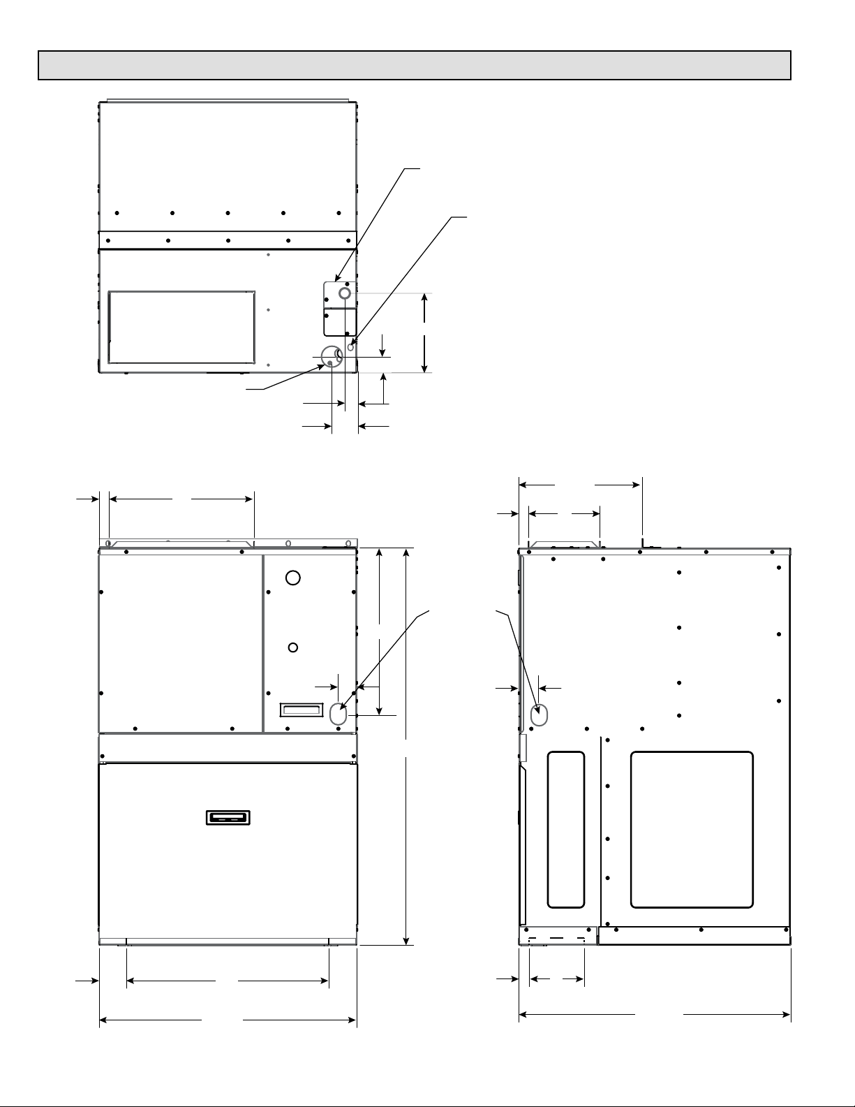
Unit Dimensions
Line Voltage
Box
Low
Voltage
Supply
1/2 Gas Inlet
161
Supply
1-1/2
2-3/4
1-3/4
8
13-3/8
81
Supply
Condensate
18-1/4
2
Drain
(HWC9 Only)
2
43-3/16
Return
2-7/8
Page 2 of 19 507388-03Issue 2110
22
61
Return
29-7/16
Installation
General
These instructions must be hung on or near the furnace in
a conspicuous place.
The MagicPak All-In-One™ HVAC system model HWC8
V-Series™ units are self-contained, gas-red heating
with electric cooling models. The unit design has been
certied by Intertek Testing Services for compliance with
the latest edition of the American National Standard ANSI
Z21.47 for direct vent central furnaces. The HWC8 models
are certied to be in compliance with the latest edition of
A.H.R.I. Standard 210/240. All models are design certied
for heating operation when red with natural or propane
gas.
These installation instructions are intended as a general
guide only, for use by an experienced, qualied contractor.
Inspection
The unit is shipped in one package, completely assembled
and wired. The Evaporator drain tubing is in the cooling
compartment behind the lter access panel.
If any damage is found, proper notation should be made on
the carrier’s freight bill. Damage claims should be led with
the carrier as quickly as possible.
Check the rating plate to conrm heating and cooling
capacities. The unit should be operated only with the type
of gas and electrical supply noted on the rating plate.
WARNING
In the State of Massachusetts:
This product must be installed by a licensed Plumber
or Gas Fitter. When exible connectors are used, the
maximum length shall not exceed 36”. When lever-type
gas shutos are used, they shall be T-handle type.
NOTE: Remove the chassis hold down shipping bracket
before installation. These brackets are located on the
outdoor side of the unit below the louver panels.
The grille side of the unit may be ush with, or extend
beyond, the face of the exterior wall, but should not be
recessed more than 2” from the face of the building and
should not be obstructed with trees, landscape materials,
or building structure.
There is no minimum clearance required on locating the
unit to an interior corner of a building.
If the unit is to be enclosed, provisions should be made
allowing access to the indoor side of the unit for changing
lters and for inspection. At least 29” of unobstructed space
should be provided in front of the indoor side, whether
enclosed or not, to permit removal of the cooling chassis
should repairs or inspection be required.
If the unit is installed in a residential garage, it must be
located or protected to avoid physical damage by vehicles.
Unit must be installed so the burners and ignition source
are not less than 18” (457 mm) above the oor. This unit
must be installed so that no electrical components are
exposed to water.
This appliance should be installed in a location such that
the vent outlet is located in the following manner:
1. Distances to windows that open, building openings, or
public walkways should be consistent with the National
Fuel Gas Code Z223.1.
2. For U.S. installations, the vent system shall terminate
a minimum horizontal clearance of 4’ from electric
meters, regulators, and relief equipment.
3. Flue products will not cause degradation to building
materials.
This furnace design is not listed for installation in mobile
homes, recreational vehicles, or outdoors.
Use of Furnace as a Construction Heater
Allied Air does not recommended the use of these units
as a construction heater during any phase of construction.
Very low return air temperature, harmful vapors and
operation of the unit with clogged or misplaced lters will
damage the unit.
Location
The design is certied for indoor installation only. The
interior portions of the unit may be surrounded by a closet
with minimum clearances to combustible material held
to 0” sides, 2” top, and 1” front and plenum. Adequate
clearance must be provided to install gas line union and
manual shuto valve as well as providing accessibility for
eld wiring. Do not install directly on carpeting, tile, or other
combustible material other than wood ooring.
507388-03 Issue 2110 Page 3 of 19
Units may be used for heating of buildings or structures
under construction, if the following conditions are met:
• The unit must be permanently installed per these
installation instructions.
• A room thermostat must control the furnace. The use
of xed jumpers that will provide continuous heating is
not allowed.
• The return air duct must be provided and sealed to the
furnace.
• Return air temperature range between 60°F (16°C)
and 80°F (27°C) must be maintained.
• Air lters must be installed in the system and must be
maintained during construction.
• Air lters must be replaced upon construction
completion.
• The input rate and temperature rise must be set per
the furnace rating plate.
• One hundred percent (100%) outdoor air must be
provided for combustion air requirements during
construction.
• The furnace heat exchanger, components, duct
system, air lters and evaporator coils must be
thoroughly cleaned following nal construction clean-
up.
• All furnace operating conditions (including ignition,
input rate, temperature rise and venting) must be
veried according to these installation instructions.
Installing With a Wall Sleeve
Refer to the installation instructions packed with the wall
sleeve and Figure 2 for guidance in assembly and mounting
using a wall sleeve.
The drain line should pitch gradually downward at least 1”
per 10’ of horizontal run to the open drain trap.
Be certain that the plastic drain tube has free drainage and
is not crimped or attened at any bend.
Drain Pan
Alternati ve
Method
To Open
Drain Trap
Return
Air Duc t
5/8
" I . D.
Plasti c Tube
(Suppli ed)
Top of Drain Tube
Must be Below
Bottom of Drai n Pan
Drain Tube - Pitch 1"
for every 10 ft.
(Field Suppli ed)
Open Drain Trap
Figure 1. HWC Evaporator Condensate Drain
Installation
Wall Sleeve
• Make sure the gaskets attached to the sleeve are not
damaged.
• Seal the space between the wall sleeve and the building
opening with non-hardening caulking compound. The
seal must be weather-tight to prevent entrance of
moisture and water into the building.
• Assure that the unit is completely seated against the
gaskets on the wall sleeve.
• Slide the unit into the sleeve. When properly nested,
the angle on top of the unit should line up with the top
ange of the sleeve and should almost touch. Fasten
the unit to the sleeve with ve screws furnished with
the sleeve.
CAUTION
The sleeve is not intended as the sole support for the
unit. An additional support must be provided near the
return opening on the unit for adequate support. The
use of vibration isolation material between the unit and
the support is recommended.
.
n
" Mi
8
2
F
L
O
O
R
Figure 2. HWC Installation
Plywood
6 x 22 Minimum Opening
""
to Ali gn with Return Ai r
Opening in Uni t.
Vibrat ion Isolat ing Material
Evaporator Condensate Drain
Install the plastic drain tube (furnished) over the 5/8” O.D.
tting in the center of the Evaporator condensate pan.
Connect other end of the drain tube to the open trap (see
Figure 1). The plastic drain connection is provided so that
it may be disconnected from the permanent drain tubing in
the building in the event it becomes necessary to remove
the cooling chassis assembly.
Page 4 of 19 507388-03Issue 2110
WARNING
Insucient combustion air can cause headaches,
nausea, dizziness or asphyxiation. It will also cause
excess water in the heat exchanger resulting in rusting
and premature heat exchanger failure. Excessive
exposure to contaminated combustion air will result
in safety and performance related problems. Avoid
exposure to the following substances in the combustion
air supply:
• Permanent wave solutions
• Chlorinated waxes and cleaners
• Chlorine base swimming pool chemicals
• Water softening chemicals
• De-icing salts or chemicals
• Carbon tetrachloride
• Halogen type refrigerants
• Cleaning solvents (such as perchloroethylene)
• Printing inks, paint removers, varnishes, etc.
• Hydrochloric acid
• Antistatic fabric softeners for clothes dryers
• Masonry acid washing materials
Combustion Air
This unit is a direct - vent furnace which obtains all air
needed for combustion from outdoors.
Venting
The venting system is an integral part of the appliance.
The venting system must not be modied or added on
to.
The unit contains a combustion inducer. The inducer
draws the combustion products out of the heat exchanger
together with dilution air and forces the mixture from the
unit to the outside. No special provisions are required for
supplying air for combustion, nor is a chimney required.
1. Seal any unused openings in the common venting
system.
2. Visually inspect the venting system for proper size and
horizontal pitch and determine there is no blockage
or restriction, leakage, corrosion, or other deciencies
which could cause an unsafe condition.
3. Insofar as is practical, close all building doors and
windows between the space in which the appliances
remaining connected to the common venting system
are located and other spaces in the building. Turn on
clothes dryers and any appliance not connected to the
common venting system. Turn on exhaust fans, such
as range hoods and bathroom exhausts, so they will
operate at maximum speed. Do not operate a summer
exhaust fan. Close replace dampers.
4. Following the lighting instructions, place the unit being
inspected in operation. Adjust the thermostat so the
appliance will operate continuously.
5. Test for spillage at the draft control relief opening after
5 minutes of main burner operation. Use the ame of
a match or candle.
6. Follow the preceding steps for each appliance
connected to the common venting system.
7. After it has been determined that each appliance
remaining connected to the common venting system
properly vents when tested as outlined above, return
doors, windows, exhaust fans, replace dampers,
and any other fuel burning appliance to their previous
condition of use.
8. If improper venting is observed during any of the above
tests, the common venting system must be corrected.
See National Fuel Gas Code, ANSI Z223.1 (latest
edition) to correct improper operation of common
venting system.
Gas Connections
The gas line to the unit should be adequately sized to
prevent undue pressure drop and should never be smaller
than the manual valve used. Consult the local utility or
National Fuel Gas Code for complete details on special
requirements in sizing gas piping.
The vent outlet must not be altered or extended.
The venting system is designed for proper operation under
all weather conditions and for winds up to 31 m.p.h.
The units supplied for operation with natural gas contain
a gas regulator which must be operated with inlet gas
pressures specied on the rating plate. If gas line pressure
exceeds this gure, an additional high pressure regulator
must be installed to reduce this pressure.
Removal of Unit from Common Venting System
When an existing furnace is removed from a common
venting system serving other appliances, the venting
system is likely to be too large to properly vent the
remaining attached appliances. The following test
should be conducted with each appliance while the other
appliances connected to the common venting system are
not in operation.
507388-03 Issue 2110 Page 5 of 19
Units for operation with propane must be converted with a
kit supplied by the manufacturer and require for operation
an inlet pressure of 11” W.C. minimum and 13” W.C.
maximum. A regulator is also required on the propane tank.
If local codes allow use of a exible gas connector, a new
listed connector must be used. Do not use a connector
which has previously serviced another gas appliance.
CAUTION
If a exible gas connector is required or allowed by
the authority that has jurisdiction, black iron pipe shall
be installed at the gas valve and extend outside the
furnace cabinet. The exible connector can then be
added between the black iron pipe and the gas supply
line.
IMPORTANT
Compounds used on threaded joints of gas piping must
be resistant to the actions of liqueed petroleum gases.
Figure 3. Gas Supply Piping
CAUTION
Never use a ame to check for gas leaks. Explosion
causing injury or death may occur.
A manual shuto valve must be located outside the unit.
The use of a union located upstream of the controls is
recommended, between the controls, and the manual
shuto valve. This will facilitate removal of controls and
manifold. See Figure 3 for recommended placement of the
union.
Provide a drip leg in the supply piping located exterior
to the unit. Piping connections must be sealed with nonhardening pipe joint compound resistant to propane.
WARNING
The furnace must be isolated from the gas supply piping
system by closing the individual manual shuto valve
during any pressure testing of gas supply piping system
at test pressures equal to or less than 1/2 psig or 14”
W.C. If the piping system is to be tested at pressures in
excess of 1/2 psig, the furnace and its individual shuto
valve must be disconnected from the gas supply piping
system. The gas valve supplied with this furnace is
rated at 1/2 psig. Any higher pressure may rupture the
pressure regulator diaphragm which will cause over-
ring of the burners and improper burner operation.
This action may produce a high concentration of carbon
monoxide which can result in asphyxiation.
Leak Check
After gas piping is completed, carefully check all piping
connections (factory and eld installed) for gas leaks. Use
a leak detecting solution or other preferred means.
NOTE: If emergency shuto is necessary, shut o the main
manual gas valve and disconnect the main power to the
furnace. The installer should properly label these devices.
CAUTION
Some soaps used for leak detection are corrosive to
certain metals. Carefully rinse piping thoroughly after
leak test has been completed. Do not use matches,
candles, ame or other sources of ignition to check for
gas leaks.
Page 6 of 19 507388-03Issue 2110

Electrical Connections
All wiring must be done in accordance with the National
Electrical Code, ANSI/NFPA No. 70 (latest edition); or local
codes, where they prevail. Any alteration of internal wiring
will void certication and warranty.
ELECTROSTATIC DISCHARGE (ESD)
Precautions and Procedures
CAUTION
Electrostatic discharge can aect electronic components.
Take precautions during furnace installation and service
to protect the furnace’s electronic controls. Precautions
will help to avoid control exposure to electrostatic
discharge by putting the furnace, the control and
the technician at the same electrostatic potential.
Neutralize electrostatic charge by touching hand and
all tools on an unpainted unit surface, such as the gas
valve or vestibule panel, before performing any service
procedure.
The rating plate indicates the operating voltage, phase,
minimum circuit ampacity, maximum fuse size, and
minimum voltage. Units must never be installed where
voltage exceeds 10% over the voltage indicated on the
rating plate.
Units are factory wired for a 230 volt power supply. If power
supply is 208 volts, it will be necessary to change a wire
connection on unit transformer from 240 volt terminal to
208 volt terminal as shown on the wiring diagram.
Exterior Junction Box and Switch
If local codes allow, a eld supplied junction box and
optional switch may be installed on the top panel to provide
an exterior electrical wiring point and disconnect. A suitable
junction box cover must be used. If a switch is used it must
meet or exceed the electrical specications shown on the
unit rating plate. The junction box, cover, and (if used)
switch are standard items that are locally available.
Installing an Exterior Junction Box
1. Remove the two screws that secure the factorysupplied cover over the rear half of the internal junction
box. Keep the front cover in place. See Figure 4.
2. Position a 4x4 junction box over the opening as shown
in Figure 5. Make sure the junction box is pulled up
against the front cover so that there is no gap. Remove
a knock-out in the box to allow the unit wiring leads
to extend into the bottom of the box. Pull the leads
through the knock-out and into the box. Remove a
knock-out for the main power supply leads.
3. Secure the junction box to the top panel using screws.
4. Connect the unit wiring leads to the main power supply
or the switch as desired. Securely attach the cover to
the junction box. When complete, the junction box
should be as shown in Figure 6.
5. The rear cover that was removed in Step 1 is not used
and may be discarded.
Rear Cover
Failure of the compressor as a result of operation on
improper voltage voids the compressor replacement
warranty.
A separate electric line with wire having a temperature rating
of 60°C should be run directly from the main supply panel
to the leads in the unit. Refer to the rating plate located on
the unit for proper fuse or breaker size. Make sure the unit
is electrically grounded in accordance with local codes or,
in the absence of local codes, with the National Electrical
Code, ANSI/NFPA No. 70 (latest edition) for installations
in the U.S.
See rating plate for minimum wire ampacity and size wire
accordingly.
507388-03 Issue 2110 Page 7 of 19
Front Cover
(Leave in place)
Figure 4.

Junction Box
Use Screws to secure
Junction box
No Gap
Remove Knock-out over opening, pull unit wiring leads through
Figure 5.
Thermostat
Install the thermostat according to the directions furnished
with it. The thermostat must be located on an inside wall
where it will not be aected by drafts, sunlight, or any other
heat producing appliances. Connect the thermostat wires
to the low voltage leads on top of the unit following the
wiring diagram attached to the unit. The heat anticipator
setting is 0.50 amp.
NOTE: For HWC8*30 models, a two-stage thermostat is
recommended for reaching highest eciency and full use
of two-stage compressor.
Air Filter
All indoor return air must be ltered. A permanent-type
lter is furnished with the unit, located directly behind the
access panel. Removing the panel permits access to the
lter. See Figure 3.
If an installation is made in which it is more desirable to
mount the lter exterior to the unit, in the return duct work
or elsewhere, the permanent lter can be used or replaced
with a disposable lter. If a disposable lter is used, refer
to the information provided in Table 1 when sizing the
disposable lter.
Figure 6.
Model Number
HWC8*12 300
HWC8*18 480
HWC8*24 480
HWC8*30 480
Filter Area
(sq. in.)
Table 1. Minimum Required Surface Area for
Disposable Filters
Supply and Return Duct(s)
Provide duct(s) sized suciently to handle the larger of the
air volumes for heating or cooling provided by this model.
Connect the supply duct to the top of the unit using canvas
connections or other exible connections to prevent noise
transmission into the duct system.
To connect the return duct to the system, use a straight
piece of duct 22” wide by 6” deep. Insert the duct into the
return opening in the bottom of the unit and ange the
duct over the existing anges around the opening inside
the unit. Make sure that all sides of the duct are anged
over to permit removal of the cooling chassis if required.
Use a exible connection to attach the remainder of the
return duct. The return duct should be sealed to the unit
casing and must terminate outside the space containing
the furnace.
Page 8 of 19 507388-03Issue 2110

Adjustments – Heating Section
Temperature Rise
At time of installation, the temperature rise must be
adjusted to be within the range specied on the unit rating
plate. See Table 2. Select a lower blower speed to increase
rise. Select a higher blower speed to reduce rise.
Pressure Regulator
The gas input must not exceed the gures shown on the
rating plate. The unit is equipped for rated inputs with
manifold pressures of: 3.5” W.C. for natural gas and 10.5”
W.C. for propane.
Blower
The unit contains a direct-drive, multispeed blower. The
proper speeds have been preset at the factory for heating
and cooling. Refer to the wiring diagram or Table 2 for
recommended heating/cooling speeds for specic models.
Direct-drive blower motors are permanently lubricated and
do not require oiling.
Limit Control
A xed temperature limit control is provided which will shut
o the gas to the main burners if the unit is overheated for
any reason. The control must not be adjusted or relocated.
The manifold pressure can be measured by removing the
pipe plug in the automatic gas valve. Connect a water
manometer and measure the pressure. See Figure 9.
Only small variations in gas input may be made by adjusting
the regulator. In no case should the nal manifold
pressure vary more than 0.3” W.C. for natural gas or
0.7” W.C. for propane.
To adjust the regulator, turn the adjusting screw on the
regulator clockwise to increase pressure and input or
counterclockwise to decrease pressure and input. See
Figure 9.
For natural gas installations, check the burner rate by
observing the gas meter (making sure that all other gas
appliances are turned o). The test hand on the meter
should be timed for at least one revolution. Note the
number of seconds for one revolution.
Cubic Feet per
BTU/HR
Input
=
Revolution
# Seconds per
Revolution
x 3600 x
Heating
Value
Adjustments – Cooling Section (HWC models)
No adjustments are required or should be attempted
regarding any of the components of the cooling chassis.
The chassis should be checked to see that none of the
wiring is loose or missing.
High Altitude Adjustments (U.S. Installations)
Ratings shown on the rating plate are for elevations up to
2000 feet. For elevations above 2000 feet, ratings should
be reduced at a rate of 4% for each 1000’ above sea level.
Refer to the National Fuel Gas Code Z223.1 (latest edition)
for further explanation.
Installation and Operation in Extremely Cold
Weather Areas
In areas where extremely cold (below – 20°F) outdoor
temperatures can be expected, some additional installation
and operating precautions should be taken. The following
precautions are taken to prevent possible vent system
ice blockage that could result in safety shutdown of the
burners:
1. Adjust to the highest achievable temperature rise
within the rise and static pressure ranges specied
on the rating plate. Depending on specic model, it
may be possible to change to a lower heating blower
speed tap to get a higher temperature rise. This also
increases comfort.
2. Make sure there are no leaks of outside air into the
return air system.
3. Keep the outside louver grille as free as possible of
any ice that may form and obstruct the ue outlet.
Cooling chassis is charged with R410A refrigerant.
507388-03 Issue 2110 Page 9 of 19

Model
HWC8N2412P12A 25 - 55 40
HWC8N3612P12A 35 - 65 50
HWC8N3612P18A 25 - 55 40
HWC8N4812P18A 35 - 65 50
HWC8N6012P18A 45 - 75 60
HWC8N3612P24A 25 - 55 40
HWC8N4812P24A 35 - 65 50
HWC8N6012P24A 45 - 75 60
N/A: Do not operate unit in heating mode using this blower speed at this external static pressure outside of the proper temperature rise range.
NOTE: HWC**30A models shipped with Low and High stage Cooling taps connected for use of the two-stage system.
* As shipped speed for Heating operation
† As shipped speed for Cooling operation
Rise
Range
(°F)
Mid
Rise
(°F)
TAP 1 (HEAT) *
TAP 4 (COOL) †
TAP 5 (COOL)
TAP 2 (HEAT) *
TAP 4 (COOL) †
TAP 5 (COOL)
TAP 1 (HEAT) *
TAP 4 (COOL) †
TAP 5 (COOL)
TAP 2 (HEAT) *
TAP 4 (COOL) †
TAP 5 (COOL)
TAP 3 (HEAT) *
TAP 4 (COOL) †
TAP 5 (COOL)
TAP 1 (HEAT) *
TAP 4 (COOL) †
TAP 5 (COOL)
TAP 2 (HEAT) *
TAP 4 (COOL) †
TAP 5 (COOL)
TAP 3 (HEAT) *
TAP 4 (COOL) †
TAP 5 (COOL)
Indoor Blower
Speed
TAP 2 (HEAT)
TAP 3 (HEAT)
TAP 1 (HEAT)
TAP 3 (HEAT)
TAP 2 (HEAT)
TAP 3 (HEAT)
TAP 1 (HEAT)
TAP 3 (HEAT)
TAP 1 (HEAT)
TAP 2 (HEAT)
TAP 2 (HEAT)
TAP 3 (HEAT)
TAP 1 (HEAT)
TAP 3 (HEAT)
TAP 1 (HEAT)
TAP 2 (HEAT)
Unit Voltage
(V)
208 or 230 455 39 415 43 385 46 355 50
208 or 230 570 31 540 33 510 35 485 37
208 or 230 655 27 625 28 595 30 575 31
208 or 230 480 460 440 415
208 or 230 530 505 485 460
208 or 230 455 59 415 N/A 385 N/A 355 N/A
208 or 230 570 47 540 50 510 53 485 55
208 or 230 655 41 625 43 595 45 575 47
208 or 230 480 460 440 415
208 or 230 530 505 485 460
208 or 230 630 42 600 44 570 47 550 48
208 or 230 770 35 740 36 715 37 690 39
208 or 230 885 30 855 31 830 32 810 33
208 or 230 560 540 520 500
208 or 230 610 580 560 535
208 or 230 630 56 600 59 570 62 550 N/A
208 or 230 770 46 740 48 715 50 690 52
208 or 230 885 40 855 42 830 43 810 44
208 or 230 560 540 520 500
208 or 230 610 580 560 535
208 or 230 630 71 600 N/A 570 N/A 550 N/A
208 or 230 770 58 740 60 715 62 690 64
208 or 230 885 50 855 52 830 54 810 55
208 or 230 560 540 520 500
208 or 230 610 580 560 535
208 or 230 630 42 600 44 570 47 550 48
208 or 230 770 35 740 36 715 37 690 39
208 or 230 885 30 855 31 830 32 810 33
208 or 230 770 750 730 710
208 or 230 820 790 770 750
208 or 230 645 55 615 58 590 60 565 63
208 or 230 780 46 755 47 730 49 710 50
208 or 230 900 40 875 41 855 42 835 43
208 or 230 770 750 730 710
208 or 230 820 790 770 750
208 or 230 645 69 615 72 590 N/A 565 N/A
208 or 230 780 57 755 59 730 61 710 63
208 or 230 900 49 875 51 855 52 835 53
208 or 230 770 750 730 710
208 or 230 820 790 770 750
0.1“ w.c. 0.2“ w.c. 0.3“ w.c. 0.4“ w.c.
SCFM
Temp
Rise
(°F)
SCFM
Table 2. Supply Airow Performance (SCFM) as a Function of External Static Pressure
Temp
Rise
(°F)
SCFM
Temp
Rise
(°F)
SCFM
Temp
Rise
(°F)
Page 10 of 19 507388-03Issue 2110

Model
HWC8N4812P30A 30-60 45
HWC8N6012P30A 45 - 75 60
N/A: Do not operate unit in heating mode using this blower speed at this external static pressure outside of the proper temperature rise range.
NOTE: HWC**30A models shipped with Low and High stage Cooling taps connected for use of the two-stage system.
* As shipped speed for Heating operation
† As shipped speed for Cooling operation
Rise
Range
(°F)
Mid
Rise
(°F)
TAP 1 (HEAT) *
TAP 3 (COOL) †
TAP 4 (COOL)
TAP 5 (COOL) †
TAP 2 (HEAT) *
TAP 3 (COOL) †
TAP 4 (COOL)
TAP 5 (COOL) †
Indoor Blower
Speed
TAP 2 (HEAT)
TAP 1 (HEAT)
Unit Voltage
(V)
208 or 230 780 46 755 47 730 49 710 50
208 or 230 900 40 875 41 855 42 835 43
208 or 230 530 510 490 465
208 or 230 570 545 530 505
208 or 230 950 920 900 885
208 or 230 780 57 755 59 730 61 710 63
208 or 230 900 49 875 51 855 52 835 53
208 or 230 530 510 490 465
208 or 230 570 545 530 505
208 or 230 950 920 900 885
0.1“ w.c. 0.2“ w.c. 0.3“ w.c. 0.4“ w.c.
SCFM
Temp
Rise
(°F)
SCFM
Table 2. Supply Airow Performance (SCFM) as a Function of External Static Pressure
Temp
Rise
(°F)
SCFM
Temp
Rise
(°F)
SCFM
Temp
Rise
(°F)
Start-Up
For Your Safety Read Before Lighting
WARNING
If you do not follow these instructions exactly, a re
or explosion may result causing property damage,
personal injury, or loss of life.
CAUTION
This furnace is equipped with a direct ignition control.
Do not attempt to manually light the burners.
To Light Main Burners
1. Turn o electrical power to unit.
2. Turn the thermostat to lowest setting.
3. Move the gas valve ON/OFF switch to the “ON”
position (Figure 7).
4. Turn on electrical power to the unit.
5. Set the room thermostat to the desired temperature.
(If the thermostat “set” temperature is above room
temperature after the pre-purge time expires, main
burners will light.)
To Shut Down Main Burners
1. Turn o electrical power to unit.
2. Move the ON/OFF switch to the “OFF” position (Figure
7).
Gas Inlet
Gas Inlet
Pressure Test
Tap
ON/OFF
Switch
Gas Manifold
Pressure Test
Tap
Figure 7. Gas Valve
Regulator Adjustment
Screw
(Under Cap)
507388-03 Issue 2110 Page 11 of 19

Operation
Operation of the unit is automatic and will provide heating
and cooling depending on the setting of the thermostat.
Heating
1. Turn on main power supply.
2. Open manual gas shuto valve.
3. Set thermostat system to “HEAT”.
4. Set thermostat to temperature desired.
Cooling
1. Turn on main power supply.
2. Set thermostat system switch to “COOL”.
3. Set thermostat to temperature desired.
Heating Sequence of Operation
1. Thermostat calls for heat.
2. Combustion blower starts and proper air ow is proven
by the pressure switch closing.
3. Blower continues to operate for 30 seconds prior to
the burners lighting.
4. Ignition control begins spark and opens gas valve. The
burners are lit. Ignition is proved through the ame
sensor.
5. Circulating air blower starts 30 seconds after the
burners light.
6. When the thermostat is satised, the burners and
combustion blower shut o.
7. Circulating air blower will shut o 120 seconds later.
Blower Control
The blower will start approximately 30 seconds after the
burners ignite and will stop approximately 120 seconds
after the thermostat is satised. The time delay is preset at
the factory and timing can not be adjusted.
Cooling Sequence of Operation
When the thermostat system switch is set for “COOL”, the
blower will start 5 seconds after the thermostat calls for
cooling and will stop 90 seconds after the thermostat is
satised.
Continuous Fan Operation
Continuous operation of the air handling blower will be
obtained if the thermostat fan switch is set to “ON”. With
the thermostat fan switch set to “AUTO”, the air handling
blower will cycle corresponding with the thermostat cycling.
To Shut Down Unit
For temporary or short periods of shutdown, set the
thermostat system switch to “OFF”. For a prolonged period
of shutdown, set the thermostat system switch to “OFF”
and turn o the electrical power supply and the gas supply
to the unit.
If the burners should fail to ignite, the ignition control will
try to ignite the burners a total of three times. Should the
burners fail to ignite within the three trials for ignition, the
ignition control will lock out for 1 hour before beginning
another ignition cycle. To reset the control, turn the
thermostat down or o for 10 seconds and then set to
desired setting. At this time, the ignition sequence will try
again.
Page 12 of 19 507388-03Issue 2110

Flue Collector Box
Combustion
Inducer
Remove these screws
to remove Combustion
inducer
Loosen these screws to
remove control board
mounting bracket
Ignition Control
Board
Remove these screws
to remove Burner
Assembly
Igniter
Gas Valve
Primary Limit
(Mounted to Vest panel)
Inducer prover
switch
Gas Manifold
Flame sensor
(mounted to top of
Burner Assembly)
Rollout switch
Burner & Manifold
Assembly
Figure 8. Component Layout
507388-03 Issue 2110 Page 13 of 19

Step 7
Mounting Brackets
Step 8
Step 9
Step 10
Figure 9. Burner & Manifold Assembly Removal
Maintenance
WARNING
ELECTRICAL SHOCK, FIRE OR EXPLOSION
HAZARD
Failure to follow safety warnings exactly could result in
dangerous operation, Serious injury, death or property
damage.
Improper servicing could result in dangerous operation,
Serious injury, death or property damage
• Before servicing, disconnect all electrical power to
furnace
• When servicing controls, label all wires prior to
disconnecting reconnect wires correctly.
• Any disassembly of components containing ue
or vent gases shall be done by a qualied service
agency.
• Verify proper operation after servicing.
Burner & Manifold
Assembly
Refer to Figure 8 for heating compartment component
layout.
It is recommended that the furnace be inspected annually
by a qualied service person.
Burner & Manifold Assembly
To remove the burner & manifold assembly:
1. Disconnect electrical service and turn o gas to the
appliance.
2. Loosen the pipe union external to the unit and remove
the gas line to the gas valve.
3. Disconnect the orange high voltage spark wire at the
ignition control board.
4. Disconnect the white ame sensor wire at the ame
sensor on top of the burner assembly.
5. Disconnect the orange and yellow wires at the rollout
switch.
Page 14 of 19 507388-03Issue 2110

6. Disconnect the red and blue wires at the gas valve.
7. Refer to Figure 9. Remove the two screws on the
burner assembly that secure it to the mounting
brackets. The mounting brackets contain pins to locate
the assembly and hold it in place after the screws are
removed. The mounting brackets are hidden until the
burner assembly is removed.
8. First, carefully pull the burner assembly toward you
until it is clear of the locating pins in the mounting
brackets.
9. Then move the assembly away from the vest panel.
10. Finally, pull the assembly from the unit.
11. Once the burner assembly is removed, the burners
can be cleaned using a bottle brush.
12. For reassembly, follow the above steps in reverse
order.
Control Board Mounting Bracket
The control board mounting bracket is designed to be
removed to allow component access for some service
procedures. The ignition control board and the inducer
prover switch are mounted to the bracket.
1. Disconnect electrical service and turn o gas to the
appliance.
2. Loosen the two screws securing the control mounting
bracket (it is not necessary to completely remove
them).
3. Lift the bracket clear of the screws and carefully lower
the bracket and ignition board to the bottom of the
compartment.
4. It may be necessary to remove the inducer prover
switch tubing at the switch.
5. For reassembly, follow the above steps in reverse
order.
Igniter
The igniter can be accessed from the front of the unit
without removing any other components. To remove the
igniter:
1. Disconnect electrical service and turn o gas to the
appliance.
2. Disconnect the orange high voltage spark wire at the
ignition control board.
3. Remove the screw and pull the igniter out of the burner
assembly.
4. For reassembly, follow the above steps in reverse
order.
Rollout Switch
If for any reason the heat exchanger becomes blocked
the temperature-sensitive rollout switch located beside the
burners will open and the ignition control will turn o the
burners. After investigating and correcting the problem,
the rollout switch must be manually reset by pressing the
button on top of it.
The rollout switch can be accessed from the front of the
unit without removing any other components. To remove
the rollout switch:
1. Disconnect electrical service and turn o gas to the
appliance.
2. Disconnect the orange and yellow wires at the rollout
switch.
3. Remove the screw and slip the rollout switch from
beneath the lanced tab on the burner assembly.
4. For reassembly, follow the above steps in reverse
order.
Flame Sensor
1. Remove the control board mounting bracket as
described previously.
2. Remove the screw and pull the ame sensor from the
top of burner assembly.
3. For reassembly, follow the above steps in reverse
order.
Primary Limit Switch
The primary limit will shut down the unit in case of
overheating and automatically resets when temperature
falls to an acceptable level. It is not eld adjustable
1. Remove the control board mounting bracket as
described previously.
2. Disconnect the two orange and yellow wires at the
primary limit switch.
3. Remove the three screws securing the primary limit
switch to the vest panel.
4. For reassembly, follow the above steps in reverse
order.
Inducer Prover Switch
1. Remove the control board mounting bracket as
described previously.
2. Disconnect the two purple leads at the inducer prover
switch.
3. If the tubing is in place, remove it.
4. Remove the screw securing the switch to the bracket
and slip the strap end out of the hole in the bracket.
5. For reassembly, follow the above steps in reverse
order.
507388-03 Issue 2110 Page 15 of 19

Burner Orices
Orices are threaded into the gas manifold. To remove
them:
1. Remove the burner & manifold assembly as described
previously.
2. Remove the four screws securing the gas manifold to
the burner assembly.
3. Remove the orices by unscrewing them. Do not use
any pipe thread sealant during reassembly.
4. For reassembly, follow the above steps in reverse
order.
Combustion Inducer
The combustion inducer can be removed for inspection,
replacement, or to access the heat exchanger and ue
tube extension for cleaning. To remove the combustion
inducer:
1. Remove the control board mounting bracket as
described previously.
2. Disconnect the black inducer motor leads.
3. Disconnect the inducer prover switch tubing at the
switch.
4. Remove the two screws on the combustion inducer
plate.
5. Pull the combustion inducer and plate toward you until
it is free of the dilution air box that supports it. Lower
the inducer and plate and rotate to pull the assembly
out of the compartment.
6. The ue tube extension can be cleaned if necessary.
Leave it in place; do not remove it from the unit.
7. For reassembly, follow the above steps in reverse
order.
Heat Exchanger
The heat exchanger should be inspected periodically and
cleaned if necessary. When cleaning use a sti brush with
a wire handle to remove scale and soot. To access the
heat exchanger tubes for cleaning:
1. Remove the burner & manifold assembly as described
previously.
2. Remove the combustion inducer as described
previously.
3. Remove the four screws securing the dilution air box
to the ue collector box.
4. Remove the nine or twelve screws (depending on
model) securing the ue collector box to the vest panel.
5. Using the wire brush, brush out the inside of each heat
exchanger tube from the burner assembly end and
from the ue collector box end.
6. Brush out the inside of the ue collector box.
7. Brush out the inside of the ue tube extension.
8. If soot buildup is excessive, clean the combustion
inducer wheel and housing.
9. When brushing is complete, blow all brushed areas
with air. Vacuum as needed.
10. For reassembly, follow the above steps in reverse
order.
Cooling Chassis
The refrigeration system contained in the cooling chassis
normally requires no maintenance since it is a closed,
self-contained system. System is charged with R410A
refrigerant. Periodic maintenance is limited to:
• Cleaning the air lter. Follow directions noted on the
lter and label attached to the access panel.
• Cleaning the condenser coil if covered with any foreign
material, lint, leaves, or other obstructions.
If servicing or major repairs are required, the complete
chassis can be removed from the unit. To remove the
chassis:
1. Shut o the main power supply.
2. Remove lter access panel and panel covering cooling
controls.
3. Remove drain hose from the drain pan.
4. Disconnect the plug-in electrical connections.
5. Disconnect two power leads at contactor (leads come
from grommet in unit partition).
6. Remove screws from panel directly in front of blower
and remove panel. Also remove additional screws
located near top edge of control panel.
7. Drape power wires and wire harnesses out of cabinet
and tape to upper panel.
8. Slide out the chassis, being careful not to damage any
seals or parts. Particular care should be taken to insure
wiring is not damaged during removal/reinstallation
process.
NOTE: Tubing is not to be used as a handle.
To reinstall the chassis, reverse the procedure outlined
above. Be sure that the chassis is inserted as far back as
it will go before replacing the screws. Side anges on the
chassis must be engaged with sealing strips on the unit
sides to prevent water and air leakage. Reconnect the
wire harness, reconnect the power leads, and replace both
access panels before turning on the main electrical power.
Page 16 of 19 507388-03Issue 2110

Wiring Diagrams
Figure 10. Wiring Diagram - HWC*12,18
507388-03 Issue 2110 Page 17 of 19

Figure 11. Wiring Diagram - HWC*24
Page 18 of 19 507388-03Issue 2110

Figure 12. Wiring Diagram - HWC*30
507388-03 Issue 2110 Page 19 of 19
 Loading...