

Page 1
INSTALLATION INSTRUCTIONS
EWC V-Series
This manual must be left with the homeowner for future reference.
This is a safety alert symbol and should never be ignored. When you see this symbol on labels or in manuals, be alert to
the potential for personal injury or death.
WARNING
Improper installation, adjustment, alteration, service
or maintenance can cause property damage, personal
injury or loss of life. Installation and service must be
performed by a licensed professional installer (or
equivalent), service agency or the gas supplier.
TM
Models
Table of Contents
Unit Dimensions ..........................................................2
Installation ...................................................................3
Electrical Connections .................................................4
Operation .....................................................................5
Maintenance ................................................................6
Wiring Diagrams ..........................................................8
WARNING
Installation and servicing of air conditioning equipment
can be hazardous due to internal refrigerant pressure
and live electrical components. Only trained and
qualied service personnel should install or service
this equipment. Installation and service performed by
unqualied persons can result in property damage,
personal injury or death.
Installation shall be made in accordance with the
requirements of the local utility and other authorities
having jurisdiction, or with the National Fuel Gas
Code, ANSI Z223.1 (latest edition) and the National
Electrical Code. Any alteration of internal wiring will void
certication and warranties.
CAUTION
WARNING
For your safety, do not store or use gasoline or other
ammable vapors and liquids in the vicinity of this or any
other appliance. Such actions could result in property
damage, personal injury, or death.
Manufactured By
Allied Air Enterprises LLC
A Lennox International, Inc. Company
215 Metropolitan Drive
West Columbia, SC 29170
Check that equipment complies with all applicable building codes, laws, and regulations for its intended use prior to installation.
507390-02 Issue 2110
These units are not approved for mobile home
applications. Such use could result in property damage,
personal injury, or death.
*P507390-02*
WARNING
(P) 507390-02
Page 1 of 12
Page 2
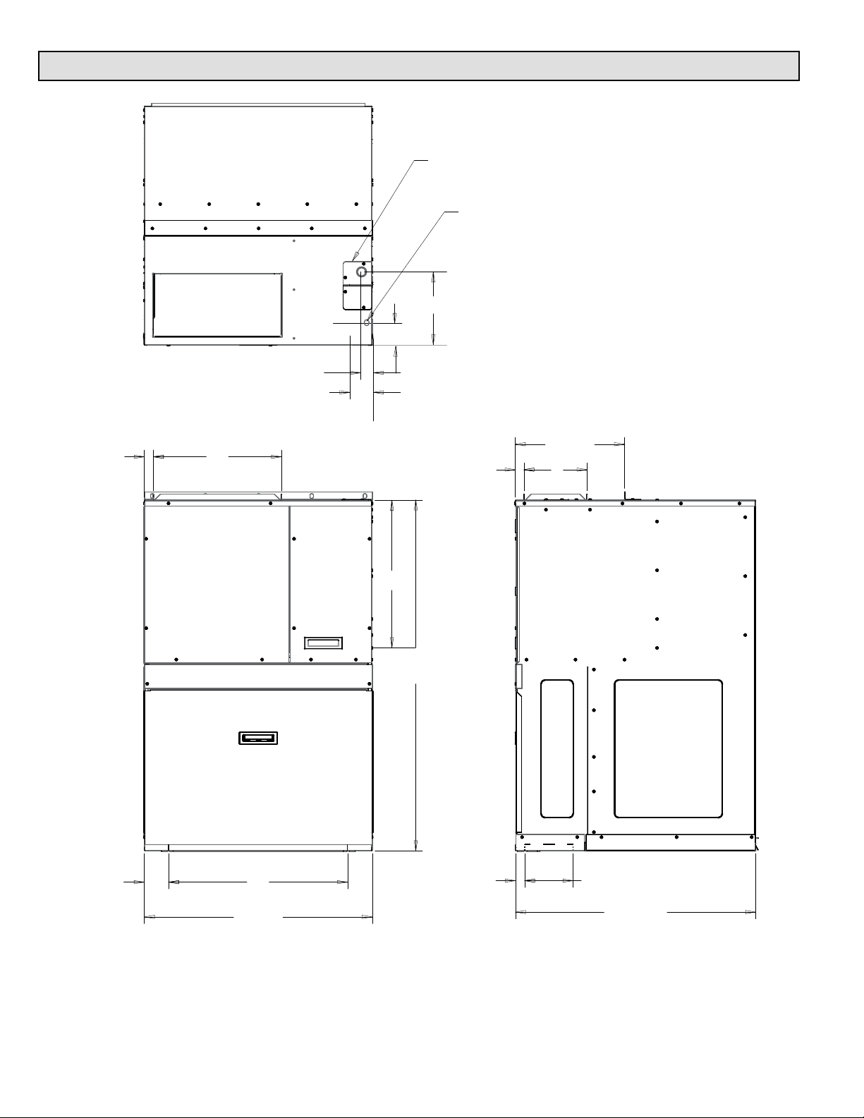
Unit Dimensions
Line Voltage
Connections
Thermostat Wiring
Connections
Supply
161
Supply
1-1/2
2 3/4
1-3/4
18-1/4
43-3/16
8
13-3/8
81
Supply
Return
2-7/8
Page 2 of 12 507390-02Issue 2110
22
27-7/8
61
29-7/16
Page 3
Installation
Installation shall be made in accordance with local utility
requirements and any other authorities having jurisdiction.
General
The MagicPak All-In-One™ HVAC system model EWC
V-Series™ unit is a self-contained electric heating and
cooling unit. This unit has been examined for compliance
with Canadian Standards Association CAN/CSA-C22.2
No. 236 (latest edition) and Underwriters Laboratories
UL 1995. This unit is also in compliance with A.H.R.I.
Performance Standard 210/240. Any alterations of internal
wiring will void these listings and warranties.
Inspection
This unit is shipped in one package, completely assembled
and wired. The drain tubing is in the cooling compartment
behind the lter access panel.
If any damage is found, proper notation should be made
on the carrier’s freight bill. Damage claims should be led
with the carrier at once. Check the rating plate to conrm
heating and cooling capacities.
NOTE: Be sure to remove the chassis hold down brackets
from the outdoor side of unit before installation. These
brackets are located below the louver panels.
Location
The unit is approved for indoor installation only. It must not
be installed completely outside. Duct connections as well
as service access must be inside the building. The interior
portions of the unit may be surrounded by a closet with
clearances to combustible material held to 0” at sides, 2”
top, and 0” front and plenum. The oor may be combustible.
The grille side of the unit may be ush with, or extend
beyond, the face of the exterior wall, but should not be
recessed more than 2” from the face of the building and
should not be obstructed with trees, landscape materials,
or building structure.
If the unit is to be enclosed, provisions should be made
allowing access to the indoor side of the unit for changing
lters and for inspection. At least 29” of unobstructed space
should be provided in front of the indoor side, whether
enclosed or not, to permit removal of the cooling chassis
should repairs or inspection be required.
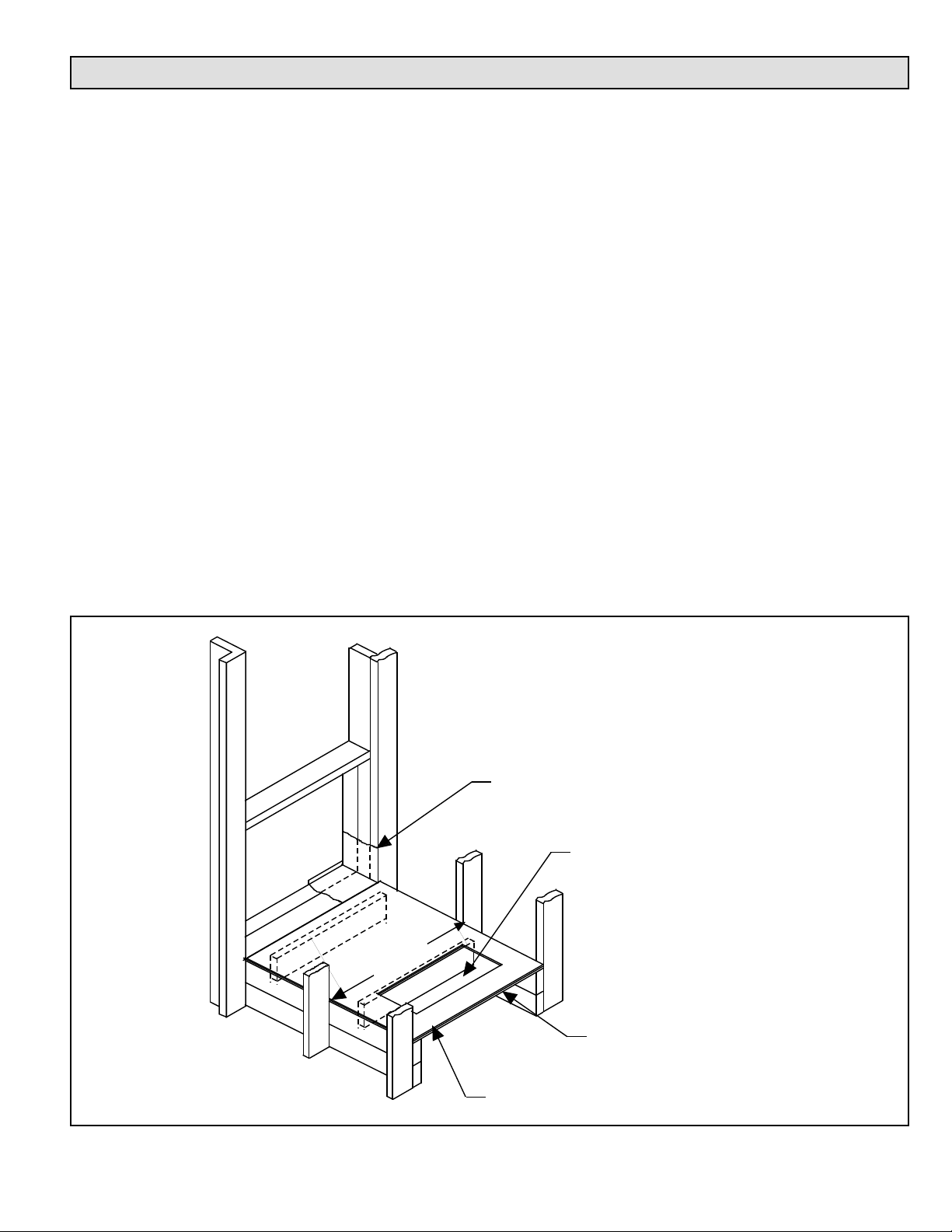
Wall Sleeve
6 x 22 Minimum Opening
""
to Align with Return Air
Opening in Unit.
.
n
" Mi
8
2
Vibration Isolating Material
FLO
O
R
Plywood
Figure 1. EWC Installation
507390-02 Issue 2110 Page 3 of 12
Page 4
Installing with a Wall Sleeve
Refer to the installation instructions packed with the wall
sleeve and Figure 1 for guidance in assembly and mounting
using a wall sleeve.
• Make sure that the gaskets attached to the sleeve are
not damaged.
• Seal the space between the wall sleeve and the
building opening using non-hardening caulking
compound. This seal must be watertight.
• Assure that the unit is completely seated against the
gaskets on the wall sleeve.
• Slide the unit into the sleeve. When properly nested,
the angle on top of the unit should line up with the top
ange of the sleeve and should almost touch. Fasten
the unit to the sleeve with ve screws furnished with
the sleeve.
CAUTION
The sleeve is not intended as the sole support for the
unit. An additional support must be provided near the
return opening on the unit for adequate support. The
use of vibration isolation material between the unit and
the support is recommended.
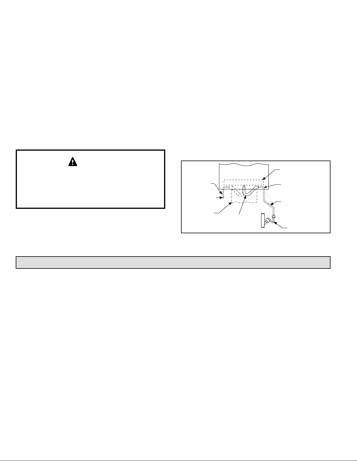
Condensate Drain
To install the condensate line, connect one end of the
plastic tube over the 5/8” O.D. tting in the center of the
condensate pan. Connect the other end to the drain tube
running to the open trap (see Figure 2).
The drain line should pitch gradually downward at least 1”
per 10 feet of horizontal run to the open drain trap.
Be certain that the plastic drain tube has free drainage and
is not crimped or attened at any bend.
Test drainage by pouring water into the drain pan under the
evaporator and see that it is removed rapidly through the
drain tubing.
The plastic drain connection is provided so that it may
be disconnected from the permanent drain tubing in
the building without unsoldering in the event it become
necessary to remove the refrigeration chassis assembly.
Drain Pan
Alternati ve
Method
To Open
Drain Trap
Return
Air Duct
5/8
" I.D.
Plasti c Tube
(Suppli ed)
Top of Drain Tube
Must be Below
Bottom of Drai n Pan
Drain Tube - Pit ch 1"
for every 10 ft.
(Field Suppli ed)
Open Drain Trap
Electrical Connections
All supply wiring should be done in accordance with
the National Electric Code, or with local codes, where
they prevail. Any alternation of internal wiring will void
certication and warranty.
NOTE: Units are factory wired for a 230-volt power supply.
If power supply is 208 volts, it will be necessary to change
a wire connection on unit transformer from 240V terminal
to 208V terminal as shown on the wiring diagram.
The rating plate indicates the operating voltage, phase,
ampacity, and maximum circuit protection. Minimum
operating voltage of the 208-230 volt model is 197 volts.
Units must never be installed where voltage exceeds 10%
of voltage indicated on the rating plate.
Failure of the compressor as a result of operation on
improper voltage voids the compressor replacement
warranty.
Figure 2. EWC Drain Installation
Thermostat
Install the thermostat according to directions furnished with
it. Select a location which will measure true air temperature.
The thermostat must be located on an inside wall where it
will not be aected by drafts, sunlight, or any other heat
producing appliances. Connect the wires to the terminal
block on the unit following the wiring diagram attached to
the unit.
NOTE: For EWC*30 models, a two-stage thermostat is
recommended for reaching highest eciency and full use
of two-stage compressor.
Air Filter
All indoor return air must be ltered before it passes through
the evaporator coil. A permanent-type lter is furnished
with the unit, located directly in front of evaporator coil.
Removing the front panel permits access to the lter.
A separate electric line for each circuit should be run
through a separate fused disconnect, from the main house
panel to the supply terminal block located in the unit.
Page 4 of 12 507390-02Issue 2110
The lter should be cleaned at least once during each of
the heating and cooling seasons and more frequently if
unusual dusty conditions are encountered. To clean the
Page 5
permanent lter, shake the lter to remove excess dirt
and/or use a vacuum cleaner. Wash the lter in soap or
detergent water and re-install after lter is dry.
The lter supplied need not be oiled after washing.
If an installation is made in which it is more desirable to
mount the lter exterior to the unit, in the return duct work
or otherwise, the permanent lter supplied can be used
or a disposable lter may be used. If a disposable lter is
used, the minimum area required is as shown in Table 1.
Ductwork
Provide ductwork suciently large to handle the larger
of the air volumes for heating or cooling provided by this
model.
Connect supply duct to top of unit using canvas connection
or other exible connection to prevent noise transmission
into the duct system.
To connect the return duct to the unit, use a straight piece
of duct 22” wide by 6” deep.
Cooling Chassis Model
Number
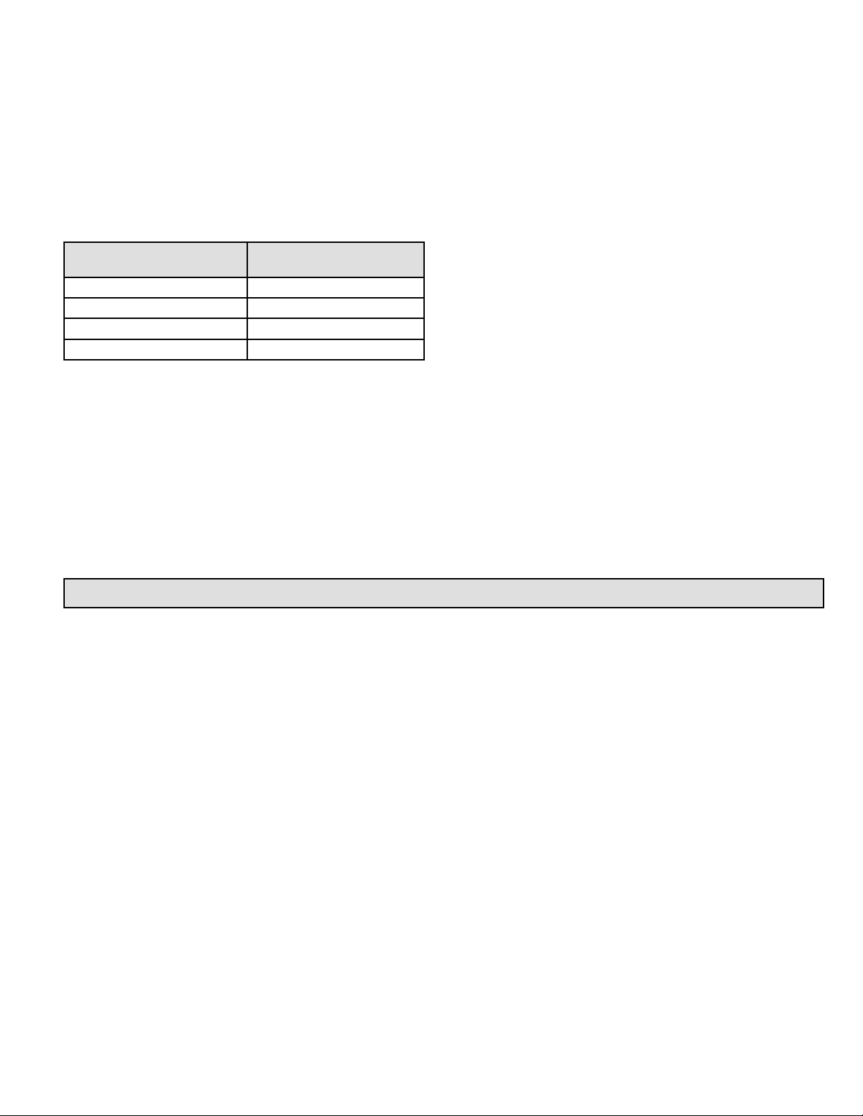
EWC*12 300
EWC*18 480
EWC*24 480
EWC*30 480
Filter Area
(sq. in.)
Table 1. Minimum Required Surface Area for
Disposable Filters
Operation
Operation of this unit is automatic and will provide heating
or cooling depending on the setting of the thermostat.
Heating
1. Turn on the main power supply.
2. Set the thermostat system switch to “HEAT”.
3. Set the thermostat heating scale to the temperature
desired.
Cooling
1. Set the thermostat system to “COOL”.
2. Set the thermostat cooling scale to the temperature
desired.
Insert the duct into the opening in the bottom of the unit
and ange the duct over the existing anges around the
opening inside the unit. Make sure that all sides of the duct
are anged over to permit removal of the cooling chassis if
required. Use a exible connection to attach the remainder
of the return ductwork.
Adjustments
No adjustments are required or should be attempted
regarding any of the components of the cooling chassis
and electric heating section.
The unit should be checked to see that none of the wiring is
loose or missing. The plug-in electrical connector between
the cooling chassis and the main control compartment
should be checked to make sure that the plug is rmly
seated and none of the wires are loose.
To Shut Down Unit
For temporary or short periods of shutdown, set the
thermostat system switch to “OFF”. For a prolonged period
of shutdown, set the thermostat system switch to “OFF”
and turn o the electrical power supply.
Blower
The unit contains a direct drive, multi-speed blower motor.
The proper speed has been set at the factory. Refer to the
wiring diagram on the unit for proper wiring connections.
Blower Operation
Continuous operation of the air handling blower will be
obtained if the thermostat fan switch is set to “ON”.
With the thermostat switch set to “AUTO”, the air handling
blower will cycle corresponding with the thermostat cycling.
507390-02 Issue 2110 Page 5 of 12
Page 6

Maintenance
Cooling Chassis
The refrigeration system contained in the cooling chassis
normally requires no maintenance since it is a closed selfcontained system. Periodic maintenance is limited to:
Cooling Chassis is charged with R410A refrigerant.
• Cleaning the evaporator air lter. Follow the directions
noted on the lter and label attached to the access
panel.
• Cleaning the condenser coil if covered with foreign
material such as lint, leaves, or other obstructions.
• Motors are permanently lubricated and do not normally
require re-oiling.
If servicing or major repairs are required, the complete
cooling chassis can be removed from the unit. Proceed as
follows:
1. Shut o the main power supply.
2. Remove the lter access panel and the panel covering
the cooling controls.
3. Remove the drain hose from the drain pan.
4. Disconnect the plug-in electrical connectors. Do
not separate the connector by pulling on the wires;
instead, grasp the connector handle.
5. Disconnect the two power leads from the contactor.
(Leads come from the Grommet in the unit partition.)
6. Remove the screws from the panel directly in front of
the blower and remove the panel. Also remove the
additional screws located near the top edge of the
control panel.
7. Drape power wires and wire harnesses out of cabinet
and tape to upper panel.
8. Slide out the chassis, being careful not to damage any
seals or parts. Particular care should be taken to insure
wiring is not damaged during removal/reinstallation
process.
NOTE: Tubing is not to be used as a handle.
To re-install the chassis, reverse the procedure outlined
above. Be sure that the chassis is inserted as far back as
it will go before replacing the screws. Side anges on the
chassis must be engaged with the sealing strips on the
unit sides to prevent water and air leakage. Reconnect the
plug-in connector, reconnect the power and four leads,
and replace both access panels before turning on the main
electric power supply.
Heating Section
No maintenance is necessary on the electric heating
elements.
Page 6 of 12 507390-02Issue 2110
Page 7
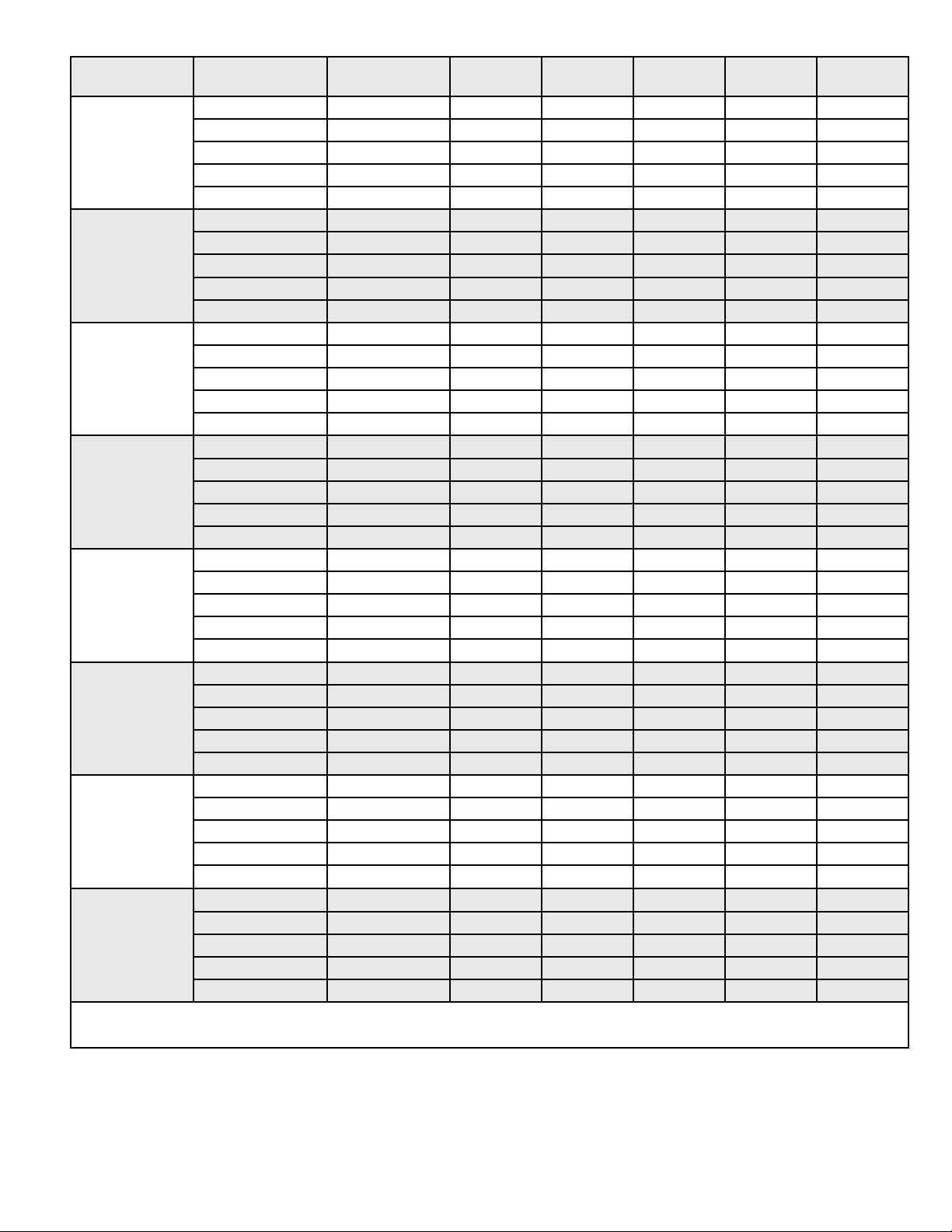
Model
Indoor Blower
Speed
Unit Voltage
(V)
0.1
" w.c.
TAP 1 (HEAT) * 208 or 230 615 590 570 545 525
TAP 2 (HEAT) 208 or 230 655 630 610 590 570
EWC0512P12A
TAP 3 (HEAT) 208 or 230 795 780 760 745 725
TAP 4 (COOL) † 208 or 230 480 460 440 415 390
TAP 5 (COOL) 208 or 230 530 505 485 460 430
TAP 1 (HEAT) 208 or 230 615 590 570 545 525
TAP 2 (HEAT) * 208 or 230 655 630 610 590 570
EWC0712P12A
TAP 3 (HEAT) 208 or 230 795 780 760 745 725
TAP 4 (COOL) † 208 or 230 480 460 440 415 390
TAP 5 (COOL) 208 or 230 530 505 485 460 430
TAP 1 (HEAT) 208 or 230 805 785 770 750 730
TAP 2 (HEAT) * 208 or 230 825 805 785 770 750
EWC0512P18A
EWC0712P18A
TAP 3 (HEAT) 208 or 230 910 890 875 860 845
TAP 4 (COOL) † 208 or 230 560 540 520 500 475
TAP 5 (COOL) 208 or 230 610 580 560 535 505
TAP 1 (HEAT) 208 or 230 805 785 770 750 730
TAP 2 (HEAT) 208 or 230 825 805 785 770 750
EWC1012P18A
TAP 3 (HEAT) * 208 or 230 910 890 875 860 845
TAP 4 (COOL) † 208 or 230 560 540 520 500 475
TAP 5 (COOL) 208 or 230 610 580 560 535 505
TAP 1 (HEAT) 208 or 230 805 785 770 750 730
TAP 2 (HEAT) 208 or 230 825 805 785 770 750
EWC1012P24A
TAP 3 (HEAT) * 208 or 230 910 890 875 860 845
TAP 4 (COOL) † 208 or 230 770 750 730 710 690
TAP 5 (COOL) 208 or 230 820 790 770 750 730
TAP 1 (HEAT) 208 or 230 805 785 770 750 730
TAP 2 (HEAT) 208 or 230 825 805 785 770 750
EWC1512P24A
TAP 3 (HEAT) * 208 or 230 910 890 875 860 845
TAP 4 (COOL) † 208 or 230 770 750 730 710 690
TAP 5 (COOL) 208 or 230 820 790 770 750 730
TAP 1 (HEAT) * 208 or 230 825 805 785 770 750
TAP 2 (HEAT) 208 or 230 910 890 875 860 845
EWC1012P30A
TAP 3 (COOL) † 208 or 230 530 510 490 465 440
TAP 4 (COOL) 208 or 230 570 545 530 505 480
TAP 5 (COOL) † 208 or 230 950 920 900 885 865
TAP 1 (HEAT) 208 or 230 825 805 785 770 750
TAP 2 (HEAT) * 208 or 230 910 890 875 860 845
EWC1512P30A
TAP 3 (COOL) † 208 or 230 530 510 490 465 440
TAP 4 (COOL) 208 or 230 570 545 530 505 480
TAP 5 (COOL) † 208 or 230 950 920 900 885 865
NOTE: EWC**30A models shipped with Low and High stage Cooling taps connected for use of the two-stage system.
* As shipped speed for Heating operation
† As shipped speed for Cooling operation
0.2
" w.c.
0.3
" w.c.
0.4
" w.c.
0.5
" w.c.
Table 2. Supply Airow Performance (SCFM) as a Function of External Static Pressure
507390-02 Issue 2110 Page 7 of 12
Page 8
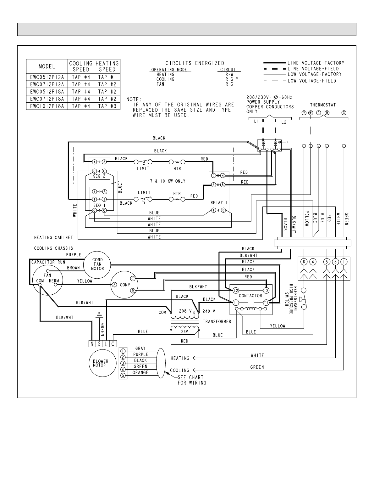
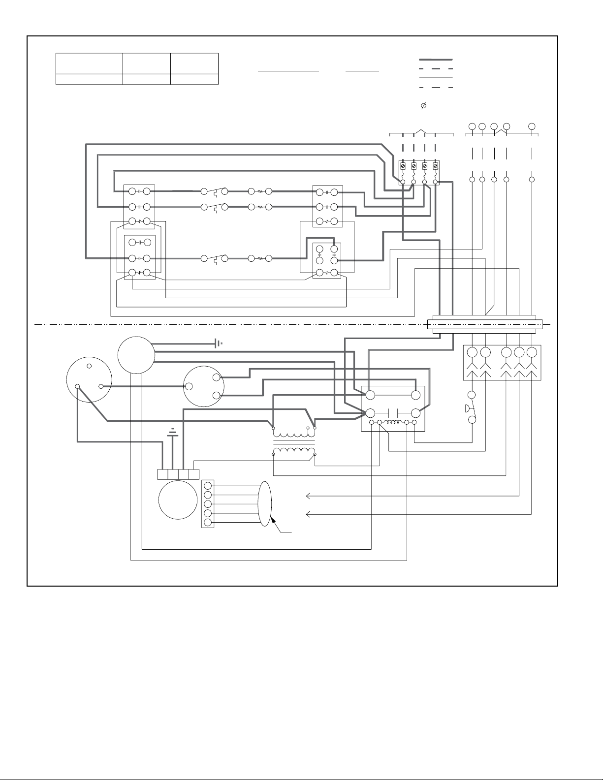
Wiring Diagrams
Figure 3. Wiring Diagram - EWC*12P12A, EWC*12P18A
Page 8 of 12 507390-02Issue 2110
Page 9
MODEL
COOLING
SPEED
HEATING
SPEED
EWC1012P24A TAP #4 TAP #3
NOTE:
IF ANY OF THE ORIGINAL WIRES ARE
REPLACED THE SAME SIZE AND TYPE
WIRE MUST BE USED.
4
5
C
C
SEQ 2
4
5
1
3
SEQ 1
C C
WHITE
HEATING CABINET
COOLING CHASSIS
CAPACITOR-RUN
FAN
COM
HERM
BLK/WHT
COND
FAN
MOTOR
GREEN & YELLOW
YELLOW
BLK/WHT
GREEN
S
NGL
BLOWER
MOTOR
BLACK
C
BLACK
BLUE
BLACK
COMP
1
2
3
4
5
LIMIT
LIMIT
C
R
BLUE
GRAY
PURPLE
BLACK
GREEN
ORANGE
CIRCUITS ENERGIZED
OPERATING MODE
HEATING
COOLING
FAN
BLACK
BLACK
HTR
HTR
BLUE
WHITE
WHITE
BLUE
WHITE
RED
RED
BLK/WHT
BLACK
COM
208V
24V
RED
HEATING
COOLING
SEE CHART
FOR WIRING
RED
RED
240V
TRANSFORMER
WHITE
GREEN
CIRCUIT
R-W
R-G-Y
R-G
2
6
RELAY 1
1
BLACK
BLUE
4
8
0
208/230V-1 -60Hz
POWER SUPPLY
COPPER CONDUCTORS
ONLY.
L1
RED
RED
BLACK
BLK/WHT
BLACK
RED
L2
CONTACTOR
L1
BLK
T2
T1
YLW
YELLOW
BLUE
LINE VOLTAGE-FACTORY
LINE VOLTAGE-FIELD
LOW VOLTAGE-FACTORY
LOW VOLTAGE-FIELD
THERMOSTAT
C
4
BLUE
R
BLUE
5
L2
BLK/WHT
BLACK
HIGH PRESSURE
REFRIGERANT
SWITCH
YGW
YELLOW
6
GREEN
WHITE
RED
3
1
YELLOW
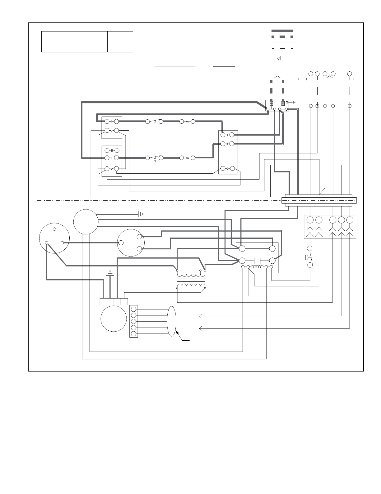
Figure 4. Wiring Diagram - EWC1012P24A
507390-02 Issue 2110 Page 9 of 12
Page 10
MODEL
COOLING
SPEED
EWC1512P24A TAP #4 TAP #3
NOTE:
IF ANY OF THE ORIGINAL WIRES ARE
REPLACED THE SAME SIZE AND TYPE
WIRE MUST BE USED.
4
1
SEQ 2
C
4
1
SEQ 1
C
COND
FAN
MOTOR
5
3
C
5
3
C
GREEN & YELLOW
YELLOW
BLK/WHT
BLACK
HEATING CABINET
COOLING CHASSIS
CAPACITOR-RUN
FAN
COM
BLK/WHT
BLACK
WHITE
HERM
N
BLACK
HEATING
BLACK
BLACK
BLUE
BLACK
GREEN
G
BLOWER
MOTOR
SPEED
S
COMP
C
L
LIMIT
LIMIT
LIMIT
1
2
3
4
5
BLUE
WHITE
BLUE
WHITE
WHITE
C
R
BLUE
PURPLE
BLACK
GREEN
ORANGE
BLACK
GRAY
CIRCUITS ENERGIZED
OPERATING MODE
HEATING
COOLING
FAN
HTR
RED
RED
HTR
HTR
RED
RED
COM
BLUE
RED
BLK/WHT
BLACK
208V
24V
RED
HEATING
COOLING
SEE CHART
FOR WIRING
4
2
8
6
1
0
RELAY 2
6
2
8
4
0
1
RELAY 1
BLACK
240V
TRANSFORMER
BLUE
WHITE
GREEN
CIRCUIT
R-W
R-G-Y
R-G
BLACK
BLACK
WHITE
RED
L2
L1
208/230V-1 -60Hz
POWER SUPPLY
COPPER CONDUCTORS
ONLY.
L1
RED
RED
BLACK
BLK/WHT
BLACK
RED
CONTACTOR
BLK
L3
T2
T1
L4
YELLOW
BLUE
YLW
LINE VOLTAGE-FACTORY
LINE VOLTAGE-FIELD
LOW VOLTAGE-FACTORY
LOW VOLTAGE-FIELD
THERMOSTAT
C
YGW
L2
YELLOW
BLUE
BLK/WHT
BLACK
HIGH PRESSURE
REFRIGERANT
SWITCH
BLUE
4
6
R
GREEN
WHITE
RED
3
1
5
YELLOW
Figure 5. Wiring Diagram - EWC1512P24A
Page 10 of 12 507390-02Issue 2110
Page 11
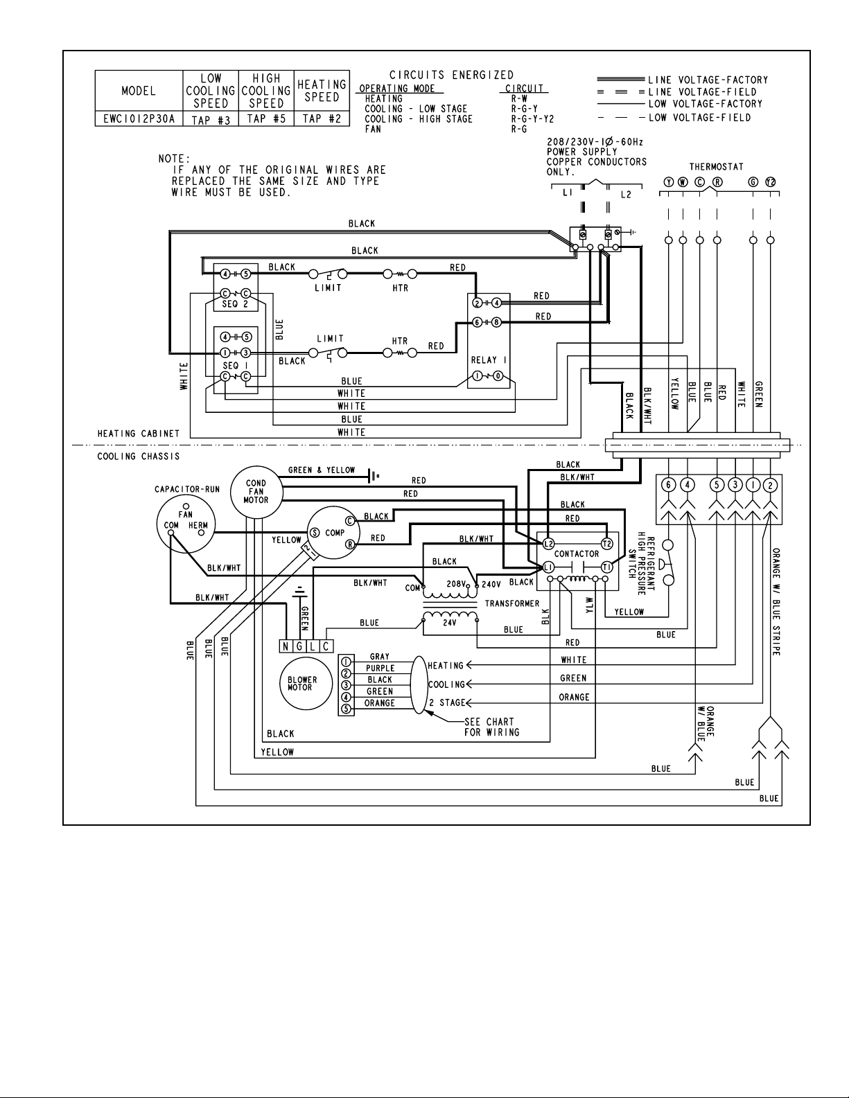
Figure 6. Wiring Diagram - EWC1012P30A
507390-02 Issue 2110 Page 11 of 12
Page 12
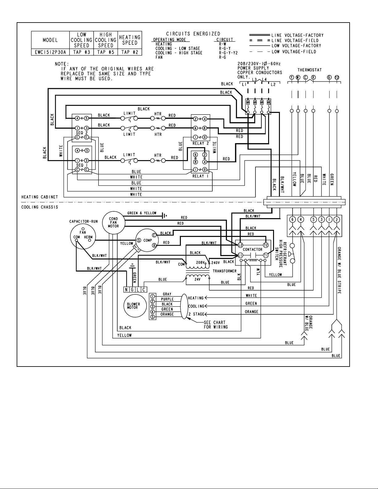
Figure 7. Wiring Diagram - EWC1512P30A
Page 12 of 12 507390-02Issue 2110
 Loading...