

Page 1
PLEASE READ THIS MANUAL CAREFULLY BEFORE USING YOUR
WINE AND BEVERAGE CENTER AND KEEP IT FOR FUTURE REFERENCE.
Wine and Beverage Center
User's Manual
Model MCWBC77DZC
Page 2

2
ENG - 2
Thank you for purchasing a Magic Chef® product. The first step to protect your new
product is to complete the product registration on our website:
www.mcappliance.com/register. The benefits of registering your product include the
following:
Once again, thank you for purchasing a Magic Chef® product.
1. Registering your product will allow us to contact you regarding a safety notification
or product update.
2. Registering your product will allow for more efficient warranty service processing
when warranty service is required.
3. Registering your product could act as your proof of purchase in the event of
insurance loss.
PRODUCT REGISTRATION
Page 3

3
ENG - 3
TABLE OF CONTENTS
PARTS 4
SPECIFICATIONS 4
IMPORTANT SAFETY INSTRUCTIONS 5
INSTALLATION INSTRUCTIONS
BEFORE USING YOUR APPLIANCE 5
FREESTANDING INSTALLATION 6
BUILT-IN INSTALLATION 6
ELECTRICAL CONNECTION 7
APPLIANCE FEATURES
DUAL TEMPERATURE ZONES 8
INTERIOR LIGHT 8
ENGAGED WINE SHELVES 8
TO REMOVE A SHELF 8
TO REPLACE A SHELF 8
UPPER ZONE 9
LOWER ZONE 9
OPERATING YOUR APPLIANCE
TEMPERATURE CONTROL AND DISPLAY 10
INDICATOR LIGHTS 10
STANDBY 10
LOCK AND UNLOCK 11
TEMPERATURE SETTING 11
INTERIOR LIGHT 11
AUTOMATIC DEFROST 12
CARE AND MAINTENANCE
CLEANING YOUR APPLIANCE 12
VACATION TIME 12
MOVING YOUR APPLIANCE 12
ENERGY SAVING TIPS 12
TROUBLESHOOTING GUIDE 13
WARRANTY 15
Page 4
4
ENG - 4
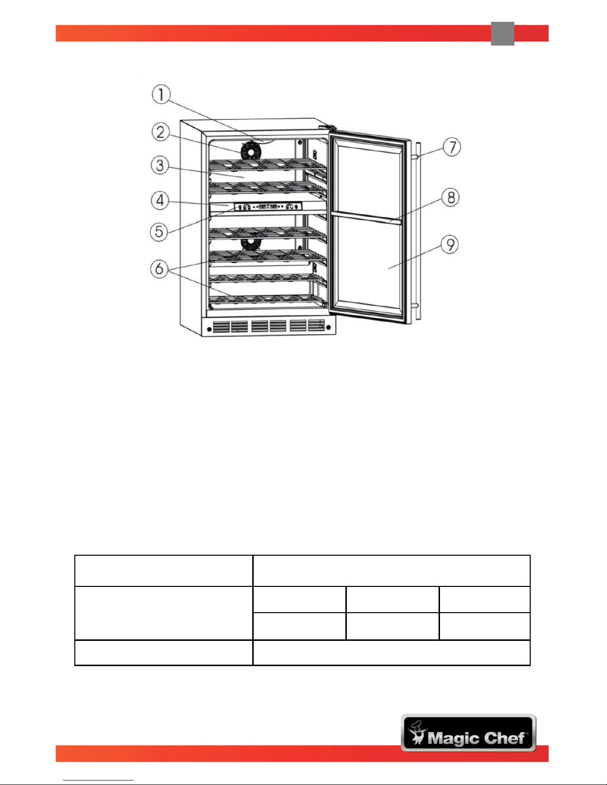
PARTS
1) Interior Light 7) Door Handle
2) Direct Current (DC) Electric Fan 8) Partition Gasket
3) Inner Rear 9) Tempered Glass Door
4) Zone Partition
5) Temperature Control & Display
6) Wire Shelf / Glass Shelf* *Shelves are available for either wine,
beverage, or combination
storage use
SPECIFICATIONS
Product Description Wine and Beverage Center
Unit Dimensions
(inches)
Width Height Depth
23.4” 34.4” 24.4”
Net Weight (lbs) 108.4 lbs
Note: Height includes door cap; Depth includes door handle.
Page 5
5
ENG - 5
IMPORTANT SAFETY INSTRUCTIONS
Before Using Your Appliance
• Remove the exterior and interior packing.
• Before connecting the appliance to the power source, let it stand upright for
approximately 4 hours. This will reduce the possibility of a malfunction in the cooling
system resulting from improper handling during transportation.
• Clean the interior surface with lukewarm water using a soft cloth (see Care and
Maintenance instructions on page 12).
INSTALLATION INSTRUCTIONS
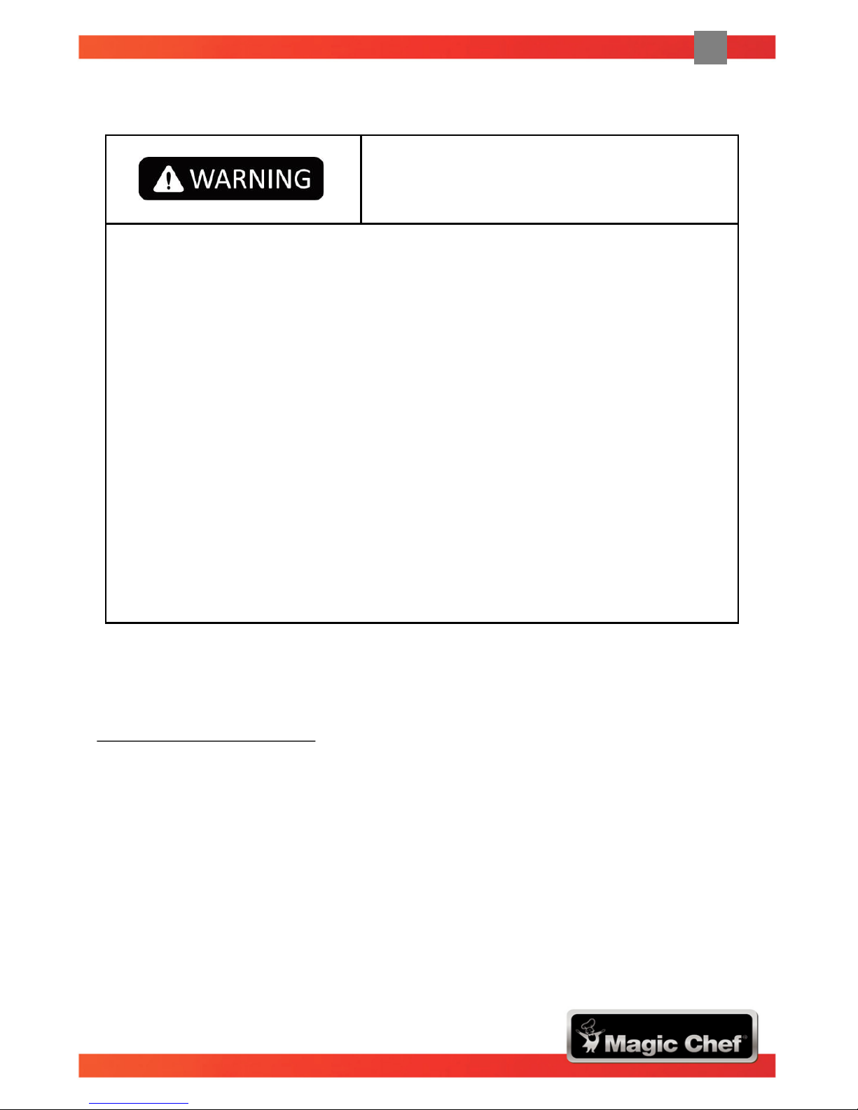
To reduce the risk of fire, electric shock and/or
injury when using your appliance, follow these
basic precautions:
Read all instructions before using the wine and beverage center.
DANGER or WARNING: Risk of child entrapment.
To avoid the possibility of child entrapment, please take the following
precautions before throwing out the appliance:
- Remove all doors from the unit.
- Leave the shelves in place so that children may not easily climb inside.
Never allow children to operate, play with, or crawl inside the appliance.
Refrigerants: All refrigeration products contain refrigerants. Under the
guidelines of federal law, refrigerants must be removed before the disposal of
the product. It is the consumer’s responsibility to comply with federal and
local regulations when disposing of this product.
Never clean the appliance parts with flammable fluids. The fumes can create a
fire hazard or explosion.
Do not store or use gasoline or any other flammable vapors and liquids in the
vicinity of this or any other appliance. The fumes can create a fire hazard or
explosion.
SAVE THESE INSTRUCTIONS
Page 6
6
ENG - 6
Freestanding Installation
• This appliance is designed to be built-in or freestanding.
• Locate the appliance away from direct sunlight and sources of heat (stove, heater,
radiator, etc.). Direct sunlight may affect the acrylic coating and heat sources may
increase electrical consumption. Ambient temperature below 68oF (20oC) or above
90oF (32oC) will hinder the performance of this appliance. This unit is not designed
for use in a garage or any other outside installation.
• Avoid locating the appliance in moist areas.
• Plug the appliance into a dedicated, properly installed grounded wall outlet. This
appliance should be operated on a separate electrical circuit from other operating
appliances. Do not under any circumstances cut or remove the third (ground) prong
from the power cord. Any questions concerning power and/or grounding should be
directed toward a certified electrician or an authorized service center. This unit is not
designed to be installed in an RV or used with an inverter.
• After plugging the appliance into a wall outlet, allow the unit to cool down for
approximately 3-4 hours before placing wine bottles or beverage cans in the
appliance.
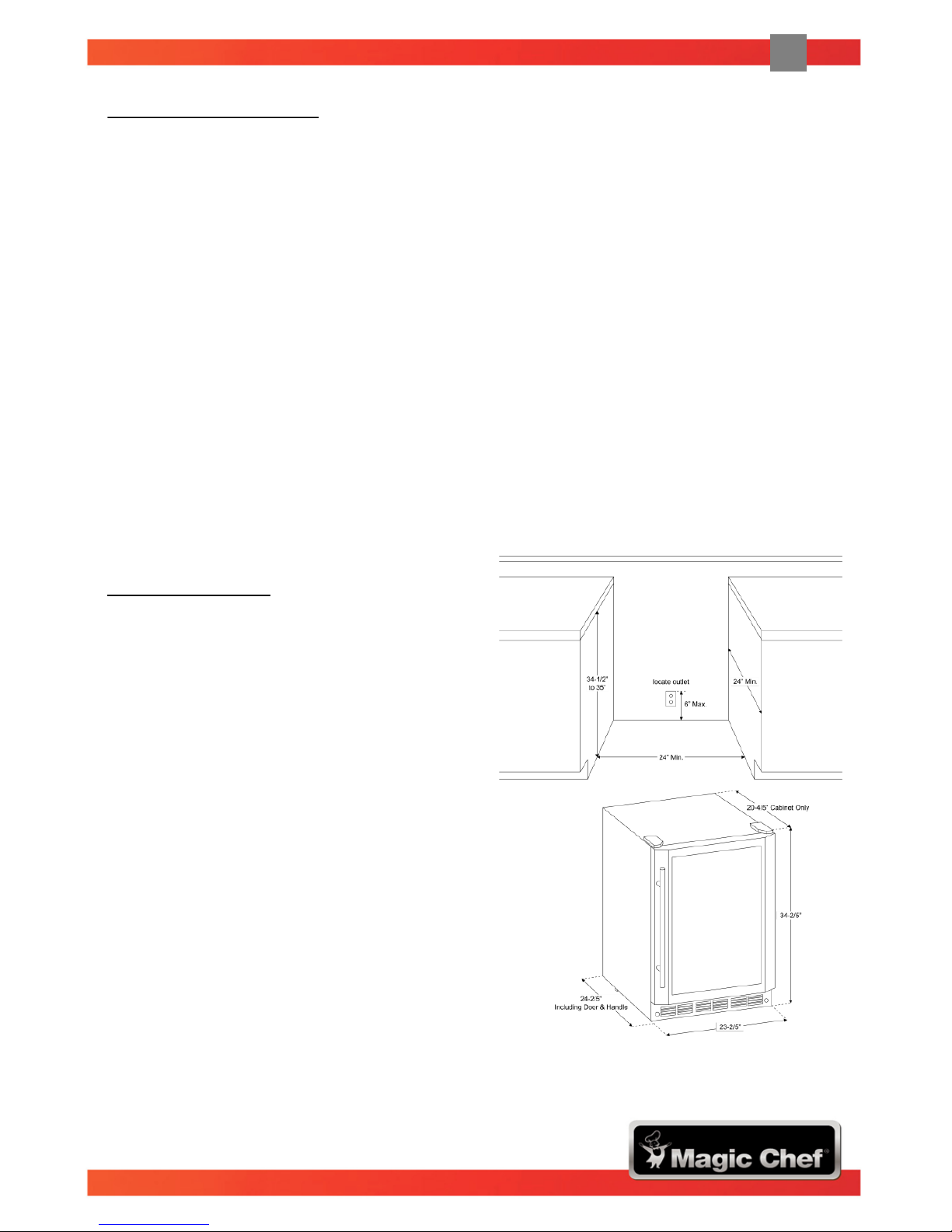
Built-In Installation
The cutout dimensions illustrated in
Figure A allows the door to swing open
and also allows access to the pull-out
shelves when installed as a built-in unit.
If you are installing the unit between
frameless cabinets, a ½” wide filler strip
or side panel may be needed on the hinge
side. The filler strip will act as a spacer
between the appliance case and the
adjacent cabinet door swing. The width of
the opening must include the filler panels.
Note: The door should protrude at least
1” beyond the surrounding cabinets.
Figure A – The cutout depth must be 24”
Page 7
7
ENG - 7
Electrical Connection
• This appliance should be properly grounded for your safety. The power cord of this
appliance is equipped with a three-prong plug which mates with standard threeprong wall outlets to minimize the possibility of electric shock.
• Do not, under any circumstances, cut or remove the third ground prong from the
power cord supplied.
• This appliance requires a standard 115V AC / 60Hz electrical outlet with a three-
prong ground.
• This appliance is not designed to be used with an inverter.
• To prevent accidental injury, the power cord should be secured behind the appliance
and not left exposed or hanging.
• Never unplug the appliance by pulling the power cord. Always grip the plug firmly and
pull straight out from the receptacle.
• Do not use an extension cord with this appliance. If the power cord is too short, have
a qualified electrician or service technician install an outlet near the appliance. The
use of an extension cord can negatively affect the performance of the unit.
If any problems with the appliance persist, please contact the Customer Service
Department at 888 775-0202 to consult with a representative. Or, visit our website at
www.mcappliance.com to request warranty service.
Improper use of the grounded plug can result in the risk of electric shock. If the
power cord is damaged, please contact an authorized service center.
Page 8
8
ENG - 8
APPLIANCE FEATURES
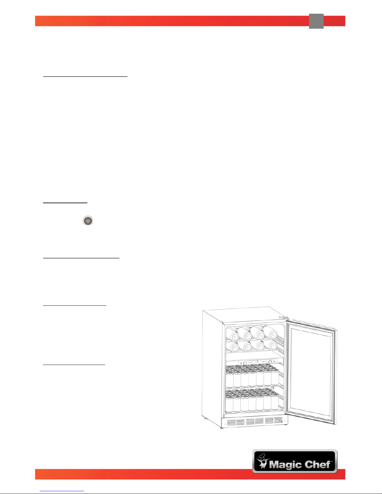
Dual Temperature Zones
• There are two zones in this appliance. They are divided by a partition.
• Each zone has its independent temperature control and display.
• Each of the two zones can be used to store wine bottles or beverages.
• The upper zone can hold up to 16 bottles or 63 cans.
• The lower zone can hold up to 28 bottles or 77 cans.
Note: Besides the wine shelves made of steel wire, two glass shelves are supplied for
your convenience to store beverages. Please keep the shelves that are temporarily
not in use in good condition for future use.
Interior Light
• Each zone has its own interior light, which can be switched on or off by pressing the
light pad on the control panel. Energy-efficient LEDs are installed for long-term
durability.
Engaged Wine Shelves
• All of the shelves have tabs to engage the cabinet on both sides.
• Any of the shelves can be removed to accommodate larger bottles.
To Remove a Shelf
• Remove all bottles (cans) from the shelves.
• Lift the shelf upward and then gently
pull out the shelf.
To Replace a Shelf
• Place the sides of the shelf back onto the
supporting guides of the cabinet and push
back until the shelf tabs slide into place.
Note: Ensure that the tabs are firmly
engaged in place before storing any bottles.
Page 9
9
ENG - 9
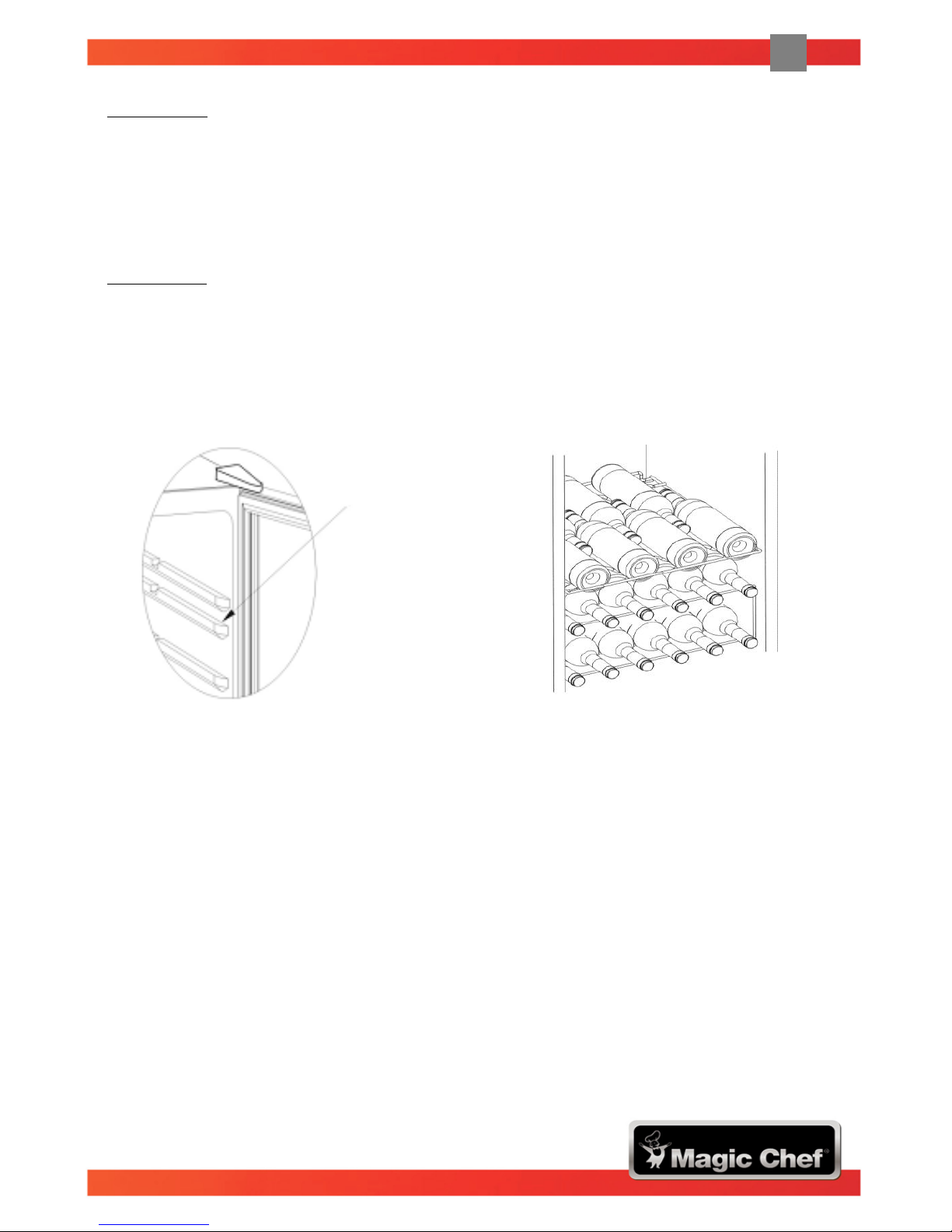
Upper Zone
• There are two wine shelves of full depth in the upper zone. Each shelf can hold up to
8 bottles with the necks of the bottles alternating front to back.
• The second supporting guide in the upper zone (counting from the top, see Figure B
below) is not designed for wine storage; the shelves are for beverage use only.
Lower Zone
• There are two wine shelves of full depth in the lower zone. Each shelf can hold up to
8 bottles with the necks of the bottles alternating front to back.
• There are two wine racks in the lower zone. Each wire rack holds up to 6 bottles with
the bottle necks facing the front (see Figure C below).
Figure B – For beverage use only Figure C – Each wire rack holds up to 6 bottles
The Second
Supporting Guide
Page 10
10
ENG - 10
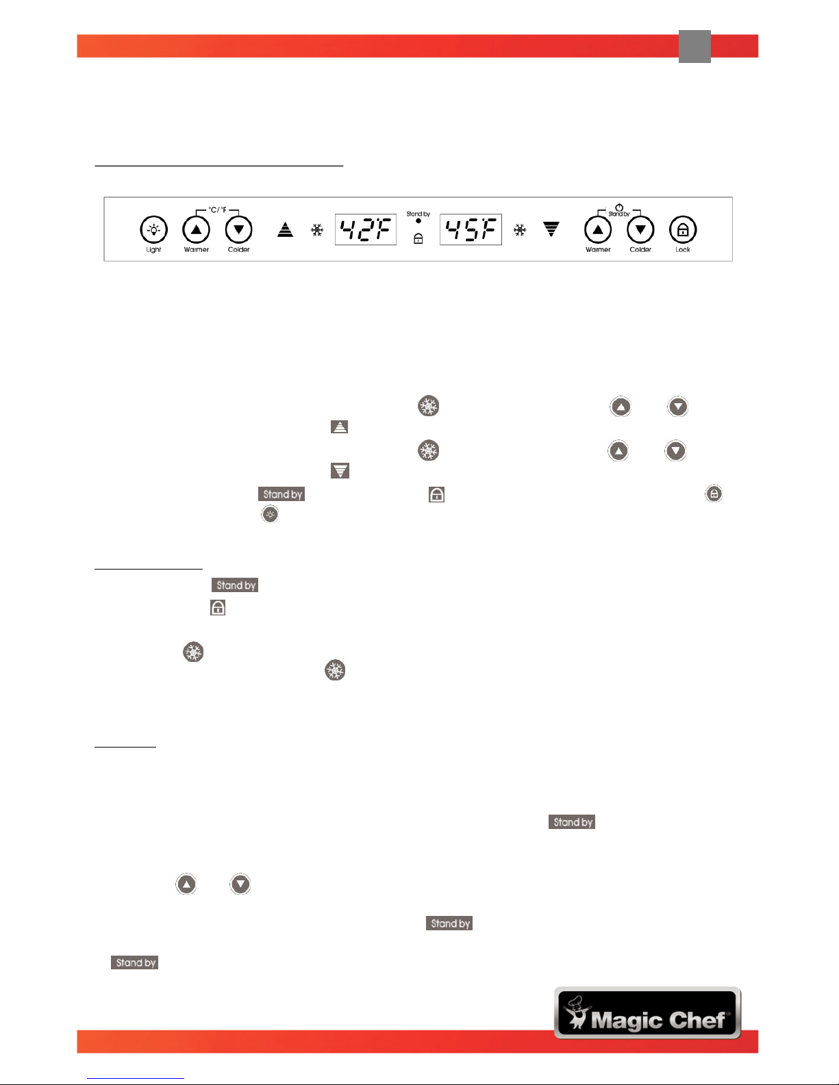
Temperature Control and Display
• The temperature in the upper zone and lower zone can be independently controlled
and displayed.
• The temperature in either zone can be controlled between 39oF to 61oF (4oC to 16oC).
(The zone temperature may have a tolerance of +/-5oF (+/-3oC) from the setting
depending on different loading and ambient conditions).
• The temperature control and display, the indicator, the warmer and colder
control pads near the symbol (left side) are for the upper zone of the wine cooler.
• The temperature control and display, the indicator, the warmer and colder
control pads near the symbol (right side) are for the lower zone of the wine cooler.
• The indicator lights for standby and lock, as well as the control pads to
lock and for lighting are for both zones.
Indicator Light
• When lit, the standby indicator light shows that the unit is in “Standby” mode.
• When lit, the lock indicator light indicates that all of the control pads are locked
and no adjustment can be made to that zone.
• When lit, indicates that the corresponding zone is in the refrigeration cycle
(compressor is running). The indicator light will turn off once the desired
temperature is reached.
Standby
• When the unit is plugged in, the display and pads will illuminate for 3 seconds and an
audible beep will be heard. Then the unit will automatically resume its previous
setting from when it was unplugged. If the unit was previously in “Standby” mode
when unplugged, it will resume in “Standby” mode and the standby indicator
will remain lit.
• You can manually set your unit to “Standby” mode by pressing and holding both the
warmer and colder buttons of the lower zone control pads for approximately 3
seconds, provided that the control pads are unlocked and no other setting is in
operation (the display does not flash). The standby indicator light will turn on
to confirm “Standby” mode. Repeating this action once more will restart the unit. The
standby indicator light will turn on to confirm “Standby” mode after restarting.
OPERATING YOUR APPLIANCE
Page 11

11
ENG - 11
Lock and Unlock
• The lock feature is designed to prevent the settings of your wine and beverage center
from being adjusted accidentally. In order to adjust any of the settings you must
unlock the control panel by pressing the lock pad for approximately 3 seconds.
Once the unit is unlocked, an audible beep will be heard and the lock indicator
light will turn off.
• If no selection is made to adjust the unit in approximately one minute, the control
panel will automatically return to the lock mode.
• To lock the unit manually, press the lock pad.
• Under locked mode, the control pad function is disabled, and the lock indicator
light will flash for 5 seconds to remind you that the control panel is locked.
Temperature Setting
• Unlock the control panel by pressing the lock pad for approximately 3 seconds.
Once the control panel is unlocked, an audible beep will be heard and the lock
indicator light will turn off.
• Under normal conditions, the temperature display indicates the current temperature
of the corresponding zone. When adjusting the temperature, the temperature display
will flash to indicate that the temperature is being adjusted.
• The temperature in the upper & lower zones can be set independently by pressing
the warmer or colder touch pads corresponding to the desired zone. The
temperature range of both zones can be set between 39oF to 61oF (4oC to 16oC).
• When the warmer or colder pad is pressed, the temperature displayed will
increase or decrease in increments of one degree. If the warmer or colder pad
is pressed and held for 2 seconds, the temperature displayed will increase or
decrease at a speed of one degree per half second.
• Once you have adjusted the upper and/or lower zone to the desired temperature,
release the temperature pad. At this time the temperature displayed will flash for
approximately 3 seconds to confirm the selected temperature. Once the display stops
flashing the temperature display will indicate the current temperature of that zone.
Note: The temperature display can be changed between Celsius and Fahrenheit by
simultaneously pressing and holding both warmer and colder pads for about 3
seconds. This unit cannot be in lock mode to perform this operation.
Interior Light
• To turn on / off the interior light, press the light pad. The unit cannot be in lock
mode to perform this operation.
Note: The light will turn OFF after the touch pad is released.
Page 12

12
ENG - 12
AUTOMATIC DEFROST
• The ice build-up on the inner back wall during compressor operation will be
automatically defrosted in a compressor off cycle.
• When defrosting is in process, the indicators for both zones will turn off, and the
circulation fans for both zones will run.
• Defrost water will drain into the drip pan, located above the compressor. Water
accumulated in the drip pan will evaporate.
Cleaning Your Appliance
• Upon installation of your new appliance, it is recommended that it be cleaned
thoroughly. Unplug the unit from the wall outlet and remove all contents.
• Wash the inside with a damp warm cloth soaked in lukewarm water and baking
soda solution. The solution should be about 2 tablespoons of baking soda to a quart
of water. Be sure to keep the door gasket (seal) clean to keep the unit running
efficiently. The outside of the appliance should be cleaned with mild detergent and
warm water. Dry the interior and exterior with a soft cloth. Dust or anything else
blocking the vent may hinder the cooling efficiency of the appliance. Vacuum the
vent if necessary.
Vacation Time
• Short vacations: Leave the appliance operating during vacations less than 3 weeks.
• Long vacations: If the appliance will not be used for 3 weeks or more, remove all
content and unplug the power cord. Clean and dry the interior thoroughly. To
prevent odor and mold growth, leave the door open slightly.
Moving Your Appliance
• Unplug the unit from the wall outlet, and then remove all contents. Securely tape
down all loose items inside your appliance. Lastly, tape the doors shut.
Energy Saving Tips
• The appliance should be located in the coolest area of the room, away from heat
producing appliances or heating ducts, and out of direct sunlight. Ensure that the
door is closed when the appliance is plugged in.
CARE AND MAINTENANCE
Page 13

13
ENG - 13
TROUBLESHOOTING GUIDE
You can solve many common appliance problems easily, saving you the cost of a
possible service call. Try the suggestions below to see if you can solve the problem
before calling for service.
PROBLEM POSSIBLE CAUSE
The appliance does not
operate.
The appliance is not plugged in.
The circuit breaker tripped or a fuse blew.
The temperature inside
the appliance is too
warm.
The temperature control is set too warm. Turn the control
to a cooler setting and allow several hours for the
temperature to stabilize.
The door is kept open too long or is opened too
frequently. Warm air enters the appliance every time the
door is opened. Open the door less often.
The door is not closed completely.
The door gasket does not seal properly.
The appliance has recently been disconnected for a period
of time. It takes 4 hours for the appliance to cool down
completely.
The temperature inside
the appliance is too cold.
The temperature control is set too cold. Turn the control
to a warmer setting and allow several hours for the
temperature to stabilize.
The unit vibrates. Check to assure that the appliance is on a level surface.
The appliance is touching the wall. Re-level the appliance
and move it away from the wall. If continued vibrations
occurs, turn off the appliance and unplug the power cord.
Contact the Customer Service Department for further
assistance.
Moisture forms on the
interior appliance walls.
The door is slightly open.
The door is kept open too long, or is opened too
frequently. Open the door less often.
The door is not sealed properly.
Moisture forms on the
outside of the appliance.
The door is slightly open, causing cold air from inside the
appliance to meet warm moist air from outside.
The door will not close
properly.
The appliance is not on a level surface.
The gasket is dirty.
Page 14

14
ENG - 14
PROBLEM POSSIBLE CAUSE
Error display on control
panel
E1: Temperature sensor error for the upper zone.
E2: Temperature sensor error for the lower zone.
E3: DC electric fan error for the upper zone.
E4: DC electric fan error for the lower zone.
If any of the above error codes occur, please contact the
Customer Service Department for further assistance. Do not
attempt to repair the unit yourself.
Page 15

15
ENG - 15
WARRANTY
LIMITED WARRANTY
MC Appliance Corporation warrants each new “Wine & Beverage Center” to be free from defects in material
and workmanship and agrees to remedy any such defect or to furnish a new part(s) (at the company’s option)
for any part(s) of the unit that has failed during the warranty period. Parts and labor expenses are covered on
this unit for a period of one year after the date of purchase. A copy of the dated sales receipt/invoice is
required to receive warranty service, replacement or refund.
In addition, MC Appliance Corporation warrants the compressor (parts only) to be free from defects in
material and workmanship for a period of five years. The consumer is responsible for all labor and
transportation expenses related to the diagnosis and replacement of the compressor after the initial one-year
warranty expires. In the event that the unit requires replacement or refund under the terms of this warranty,
the consumer is responsible for all transportation expenses to return the unit to our factory prior to receiving
a replacement unit or refund. A refund or replacement will be issued at the discretion of MC Appliance
Corporation.
This warranty covers appliances in use within the contiguous United States, Alaska, Hawaii, and Puerto Rico.
The warranty does not cover the following:
LIMITATIONS OF REMEDIES AND EXCLUSIONS
Product repair in accordance with the terms herein, is your sole and exclusive remedy under this limited
warranty. Any and all implied warranties including merchantability and fitness for a particular purpose are
hereby limited to one year or the shortest period allowed by law. MC Appliance Corporation is not liable for
incidental or consequential damages and no representative or person is authorized to assume for us any
other liability in connection with the sale of this product. Under no circumstances is the consumer permitted
to return this unit to the factory without the prior written consent of MC Appliance Corporation.
Some states prohibit the exclusion or limitation of incidental or consequential damages, or limitations on
implied warranties. This warranty gives you specific rights, and you may also have other rights which vary
from state to state.
For Service or Assistance, please call 888-775-0202. Or visit us on the web at www.mcappliance.com to
request warranty service or order parts.
• Damages due to shipping damage or improper installation
• Damages due to misuse or abuse
• Punctures to the evaporator system due to improper defrosting of the unit
• Content losses due to failure of the unit
• Repairs performed by unauthorized service agents
• Service calls that do not involve defects in material and workmanship, such as instruction on proper use of the product or
improper installation
• Replacement or resetting of house fuses or circuit breakers
• Failure of this product if used for purposes other than its intended purpose
• Disposal costs of failed units not returned to our factory
• Any delivery or installation costs incurred as the result of a unit that fails to perform as specified
• Expenses for travel and transportation for product service if your appliance is located in a remote area where service by
an authorized service technician is not available
• The removal and reinstallation of your appliance if it is installed in an inaccessible location or is not installed in
accordance with published installation instructions
• Refunds for non-repairable products are limited to the price paid for the unit per the sales receipt
• This warranty is non-transferable. This warranty applies only to the original purchaser and does not extend to any
subsequent owner(s)
Model Parts & Labor Compressor (Parts Only) Type of Service
MCWBC77DZC One Year Five Years In-Home
Page 16

CNA International, Inc. d/b/a MC Appliance Corporation. All rights reserved.
Magic Chef® is a registered trademark of CNA International, Inc.
www.mcappliance.com Printed in China
Page 17

Modelo MCWBC77DZC
LEA ESTE MANUAL ANTES DE UTILIZAR SU CENTRO DE BEBIDAS Y
VINOS Y GUÁRDELO PARA FUTURA REFERENCIA.
Centro de bebidas y vinos
Manual del usuario
Page 18

2
SPN - 2
Gracias por comprar el producto Magic Chef®. El primer paso para proteger su nuevo
producto es completar la forma de registración en nuestra pagina web:
www.mcappliance.com/register. Los beneficios de registrar su producto incluyen lo
siguiente:
Una vez más gracias por comprar un producto marca Magic Chef®.
1. Al registrar su producto nos permite contactarle para notificarle de un cambio de
seguridad o actualización del producto.
2. Si llegara a necesitar servicio bajo garantía, registrando su producto nos permite
ser más eficiente en procesar el servicio.
3. En el evento que usted tenga una perdida que esta cubierto por un seguro,
registrando su producto puede servir como prueba de su compra.
REGISTRACIÓN DEL PRODUCTO
Page 19

3
SPN - 3
INDICE DE MATERIAS
PARTES 4
ESPECIFICACIONES 4
LAS INSTRUCCIONES IMPORTANTES DE LA SEGURIDAD 5
INSTRUCCIONES DE INSTALACIÓN
ANTES DE UTILIZAR SU REFRIGERADOR 5
INSTALACIÓN AUTÓNOMA 6
INSTALACIÓN PARA EMPOTRAR 6
CONEXIÓN ELÉCTRICA 7
CARACTERÍSTICAS DEL APARATO
DOS ZONAS DE TEMPERATURA 8
LUZ INTERIOR 8
ESTANTES PARA EL VINO 8
PARA RETIRAR UN ESTANTE 8
PARA VOLVER A COLOCAR UN ESTANTE 8
ZONA SUPERIOR 9
ZONA INFERIOR 9
FUNCIONAMIENTO DE LA UNIDAD
CONTROL DE TEMPERATURA Y VISOR 10
INDICADOR LUMÍNICO 10
ESPERA 10
TRABADO Y DESTRABADO 11
PARA FIJAR LA TEMPERATURA 11
LUZ INTERIOR 11
DESCONGELAMIENTO AUTOMÁTICO 12
CUIDADO Y MANTENIMIENTO
PARA LIMPIAR SU APARATO 12
EN LAS VACACIONES 12
PARA CAMBIAR DE LUGAR SU APARATO 12
RECOMENDACIONES PARA AHORRAR ENERGÍA 12
GUÍA DE RESOLUCIÓN DE PROBLEMAS 13
GARANTÍA 15
Page 20

4
SPN - 4
PARTES
1) Luz interior 7) Manija de la puerta
2) Ventilador eléctrico DC 8) Junta de la división
3) Pared posterior interna 9) Puerta de vidrio templado
4) División de zonas
5) Control de temperatura y visor
6) Anaquel de alambre o vidrio* *Anaqueles utilizables ya sea para almacenamiento
de vinos o de bebidas combinadas
ESPECIFICACIONES
Descripción de producto Centro de bebidas y vinos
Dimensiones
(pulgadas) de unidad
Anchura Altura Profundidad
23.4” 34.4” 24.4”
Peso neto (kg) 54.2 kg
Nota: La altura incluye la cubierta de puerta; profundidad incluye la manija de la
puerta.
Page 21

5
SPN - 5
LAS INSTRUCCIONES IMPORTANTES DE LA SEGURIDAD
Antes de utilizar su refrigerador
• Retire el material de embalaje del exterior e interior.
• Antes de conectar el refrigerador a la fuente de alimentación, déjelo en posición
vertical durante 4 horas aproximadamente. De esta forma, se reducirá la posibilidad
de mal funcionamiento del sistema de refrigeración debido a manipulación incorrecta
durante el traslado.
• Limpie la superficie interior con agua tibia y paño suave (consulte las instrucciones de
cuide y la conservacion en la página 12).
INSTRUCCIONES DE INSTALACIÓN
Para reducir el riesgo de incendios, golpes de
corriente o lesiones cuando utilice su
refrigerador, sírvase tener en cuenta las
siguientes recomendaciones básicas:
Lea atentamente todas las instrucciones antes de usar el enfriadora de vino.
El PELIGRO o ADVIRTIENDO: Riesgo de que los niños queden atrapados.
Para evitar este riesgo, sírvase observar las siguientes recomendaciones antes
de lanzar fuera del refrigerador:
- Retire la puerta del aparato.
- Deje los estantes en lugar de modo que los niños no puedan subir
fácilmente adentro.
No deje que los niños usen el Refrigerador, jueguen con él o se introduzcan en
el interior.
Refrigerantes: Todos los productos de la refrigeración contienen los
refrigerantes, que debajo de las pautas de la ley federal se deben quitar antes
de la disposición del producto. Es la responsabilidad del consumidor
conformarse con regulaciones federales y locales al disponer de este
producto.
No limpie las partes del refrigerador con productos inflamables. Los vapores
pueden originar un incendio o explosión.
No almacene ni use gasolina ni ningún otro gas o líquido inflamable cuando se
encuentre cerca de este refrigerador u otro. Los vapores pueden originar un
incendio o explosión.
GUARDE ESTAS INSTRUCCIONES
Page 22

6
SPN - 6
Instalación autónoma
• Este electrodoméstico está diseñado para funcionar apoyado sobre el piso y no debe
empotrarse ni embutirse en la pared.
• Ubique el refrigerador fuera de la luz directa del sol y otras fuentes de calor (horno,
calentador, radiador, etc.). La luz directa del sol puede afectar la cubierta de acrílico y
las fuentes de calor pueden aumentar el consumo eléctrico. La temperatura
ambiente debajo de 68°F (20°C) o sobre 90°F (32°C) obstaculizará el funcionamiento
de esta aplicación. Esta unidad no se diseña para el uso en un garage o ninguna otra
instalación exterior.
• No coloque el refrigerador en ambientes húmedos.
• Enchufe el refrigerador en un toma corriente con la debida descarga a tierra utilizado
exclusivamente para este aparato. El centro para vinos y bebidas debe funcionar en
un circuito eléctrico separado de otros electrodomésticos. No corte ni retire la
tercera pata (descarga a tierra) del enchufe bajo ninguna circunstancia. Cualquier
duda relacionada con la red de electricidad y/o la descarga a tierra debe resolverse
con un electricista certificado o un centro de servicios autorizado. Esta unidad no se
diseña para ser instalada en un RV o para ser utilizada con un inversor.
• Después de enchufar en el tomacorriente de pared, prende la unidad y permite la
unidad enfríe durante 3 ó 4 horas antes de colocar alimentos en el interior.
Instalación para empotrar
Las dimensiones de corte ilustradas en la
Figura A permiten que la puerta se abra y
también el acceso a los estantes
extraíbles. Si instala la unidad entre
gabinetes sin marco, es posible que
necesite un panel lateral o un material de
relleno de ½” de ancho del lado de la
bisagra. El material de relleno actuará
como separador entre la carcasa del
electrodoméstico y el movimiento de la
puerta del gabinete adyacente. El ancho
de la abertura debe incluir los paneles de
relleno.
Nota: La puerta debe resaltar por lo
menos el 1“ más allá de los gabinetes
circundantes.
Figura A – La profundidad del recorte debe
ser el 24”
Page 23

7
SPN - 7
Conexión eléctrica
• El refrigerador debe estar adecuadamente conectado a tierra para su seguridad. El
cable de electricidad de este electrodoméstico cuenta con un enchufe de tres patas
apto para los tomacorrientes de pared con tres patas para minimizar las posibilidades
de golpes de corriente.
• No corte ni retire la tercera pata de descarga a tierra del enchufe bajo ninguna
circunstancia.
• Este equipo debe conectarse a un toma corriente de tres patas con descarga a tierra
instalado en una red estándar de electricidad con corriente 115 Volt CA / 60Hz.
• Este refrigerador no se diseña para ser utilizado con un inversor.
• El cable debe mantenerse recogido detrás del refrigerador; no debe dejarse a la vista
ni colgando para prevenir accidentes.
• No desenchufar tirando del cable. Tome el enchufe con firmeza y tire en dirección
opuesta al receptáculo.
• No utilice prolongaciones para conectar este aparato. Si el cable es muy corto, llame
a un electricista o técnico calificado para que instale un toma corriente cerca del
equipo. El uso de cables de prolongación puede perjudicar el funcionamiento de la
unidad.
Si persisten algunos problemas con la aplicación, entre en contacto con por favor
nuestro departamento del servicio de cliente para consultar con un representante en
888 775-0202 o visitenos en www.mcappliance.com para solicitar de la garantía.
El uso indebido de la descarga a tierra puede causar golpes de corriente. Si el
cable de alimentación está dañado, hágalo reemplazar con un servicio autorizado.
Page 24

8
SPN - 8
CARACTERÍSTICAS DEL APARATO
Dos zonas de temperatura
• La enfriadora tiene dos zonas divididas por una separación.
• Cada zona tiene su propio control de temperatura y visor.
• Cualquiera de las dos zonas se puede usar para guardar botellas de vino o bebidas.
• La zona superior tiene capacidad para 16 botellas o 63 latas.
• La zona inferior tiene capacidad para 28 botellas o 77 latas.
Nota: Además de los anaqueles de alambre de acero para vino, se suministran dos anaqueles
de vidrio para facilitar el almacenamiento de bebidas. Mantenga en buenas condiciones los
anaqueles que se encuentren temporalmente fuera de uso para poder utilizarlos en el futuro.
Luz interior
Cada zona tiene su propia luz interior, que puede prenderse y apagarse pulsando la
tecla (luz) en el panel de control. Cuenta con LED de larga duración y alto
rendimiento para aumentar la vida útil y ahorrar energía.
Estantes para el vino
• Todos los estantes para vino tienen pestañas que calzan a ambos lados del gabinete.
• Se puede retirar cualquiera de los estantes para acomodar botellas más grandes.
Para retirar un estante
• Retire todas las botellas (latas) del estante.
• Levante el estante hacia arriba y retire
con suavidad.
Para volver a colocar un estante
Coloque los lados del estante de nuevo en
las guías de apoyo del gabinete y empuje
hacia atrás hasta que las pestañas del
estante calcen en su lugar.
Nota: Verifique que las pestañas estén
correctamente calzadas en su lugar antes
de apoyar las botellas.
Page 25

9
SPN - 9
La zona superior
• Cuenta con dos estantes de gran profundidad para acomodar las botellas de vino.
Cada estante tiene capacidad para 8 botellas, alternado la posición del cuello hacia
delante y hacia atrás.
• La segunda guía de apoyo de la parte superior (contados a partir de la parte superior,
ver Figura B siguiente) no está diseñada para estantes para vino. Para los anaqueles
de bebidas solamente.
La zona inferior
• Cuenta también con dos estantes de gran profundidad para acomodar las botellas de
vino. Cada estante tiene capacidad para 8 botellas, alternado la posición del cuello
hacia delante y hacia atrás.
• La rejilla de abajo de la zona inferior, con dos pisos, tiene capacidad para 6 botellas en
cada piso, con el cuello de la botella hacia delante (ver Figura C siguiente).
Figura B – Para las bebidas solamente Figura C – Tiene capacidad para 6 botellas
en cada piso
La segunda
guía de apoyo
Page 26

10
ENG - 10
Control de temperatura y visor
• Se puede ver y controlar en forma independiente la temperatura de la zona superior
y la zona inferior.
• La temperatura de cada zona se puede ajustar entre 39°F y 61°F (de 4°C a 16°C). (La
temperatura de la zona puede variar +/-5°F (+/-3°C) con respecto al valor fijado,
según la carga y las condiciones ambientales).
• El visor de la temperatura, el indicador , las teclas de control (más caliente) y
(más frío) cerca del símbolo (a la izquierda) corresponden a la zona superior de
la enfriadora de vino.
• El visor de la temperatura, el indicador , las teclas de control (más caliente) y
(más frío) cerca del símbolo (a la derecha) corresponden a la zona inferior de la
enfriadora de vino.
• Los indicadores y , y las teclas de control (trabado) y (luz)
corresponden a ambas zonas.
Indicador lumínico
• Cuando está prendida, la luz del indicador señala que la unidad está en modo
“Standby” (espera).
• Cuando está prendida, la luz del indicador señala que todas las teclas de control
están trabadas y que ningún valor de esa zona se puede modificar.
• Cuando está prendida, la luz del indicador señala que la zona correspondiente
está en el ciclo de refrigeración (está funcionando el compresor). La luz del indicador
se apagará cuando la unidad alcance la temperatura deseada.
Espera
• Siempre que se encienda la unidad, el visor y las luces indicadoras se iluminarán por 3
segundos y se escuchará al mismo tiempo una señal sonora. Luego, la unidad
reanudará su funcionamiento automáticamente con la configuración que tenía
cuando fue apagada por última vez. Si al ser apagada la unidad se encontraba en
modo “en espera”, reanudará el modo “en espera” y se iluminará la luz
indicadora .
• Usted puede configurar manualmente su unidad en modo “en espera” presionando y
manteniendo presionadas a la vez las teclas (más temperatura) y (menos
temperatura) para la zona inferior por aproximadamente 3 segundos, siempre que
las teclas se encuentren desbloqueadas y no haya ninguna otra operación de
configuración en proceso (el visor no debe estar titilando). El indicador se
encenderá para confirmar esta configuración. Repetir la acción una vez más se
reiniciará la unidad.
OPERATING YOUR APPLIANCE
Page 27

11
SPN - 11
Trabado y destrabado
• El mecanismo de traba está diseñado para impedir que los controles de la enfriadora de vino se
modifiquen en forma accidental. Para poder ajustar cualquiera de los controles, debe
destrabar el panel de control oprimiendo la tecla “trabar” durante aproximadamente 3
segundos. Una vez que la unidad está destrabada, se escuchará un sonido y se apagará la luz
del indicador “trabar”.
• Si no se modifica ninguno de los controles de la unidad en aproximadamente un minuto, el
panel de control regresará automáticamente al modo “trabar”.
• Para trabar la unidad manualmente, pulsar la tecla “trabar”.
• Cuando la unidad se encuentre bloqueada, ninguna tecla que se presione funcionará, pero el
indicador titilará por 5 segundos para recordarle que la tecla que está presionando se
encuentra bloqueada.
Para fijar la temperatura
• Destrabe el panel de control pulsando la tecla durante 3 segundos aproximadamente. Una
vez que el panel de control esté destrabado, se escuchará un sonido y se apagará la luz del
indicador .
• En condiciones normales, el visor de la temperatura indica la temperatura de la zona. Cuando
se ajusta la temperatura, la luz del visor de la temperatura se ilumina en forma intermitente
para indicar que se está modificando la temperatura.
• La temperatura de la zona superior y de la zona inferior se pueden fijar en forma
independiente pulsando las teclas (más caliente) o (más frío) que correspondan a esa
zona. El rango de temperaturas de ambas zonas puede variar entre 39°F y 61°F (de 4°C a 16°C).
• Cuando se pulsa la tecla (más caliente) o (más frío), la temperatura que aparece en el
visor aumenta o disminuye de a un grado. Cuando se mantiene apretada durante 2 segundos
la tecla (más caliente) o (más frío), la temperatura que aparece en el visor aumenta o
disminuye a una velocidad de un grado por cada medio segundo.
• Una vez que ha fijado la temperatura deseada en la zona superior o en la zona inferior, suelte
la tecla de la temperatura. En ese momento, se ilumina intermitentemente durante
aproximadamente 3 segundos la temperatura que aparece en el visor para confirmar cuál es la
temperatura elegida. Una vez que la luz deja de prender y apagar, el visor muestra la
temperatura de esa zona.
Nota: Se puede modificar la programación para que muestre la temperatura en grados
centígrados y Fahrenheit simultáneamente pulsando y manteniendo oprimidas ambas teclas
(más caliente) y (más frío) durante aproximadamente 3 segundos. La unidad no puede
estar en modo (trabar) al realizar esta operación.
Luz interior
• Para prender/ apagar la luz interior, pulse la tecla (luz). La unidad no puede estar en modo
(trabar) al realizar esta operación.
Nota: La luz se apagará después de soltar la tecla digital.
Page 28

12
SPN - 12
DESCONGELAMIENTO AUTOMÁTICO
La acumulación de hielo del panel posterior durante el funcionamiento del compresor se
descongelará automáticamente cuando el compresor no esté funcionando.
Cuando se produce el descongelamiento, se apagan los indicadores de las dos zonas y
trabajan los ventiladores de circulación de las dos zonas.
• El agua de descongelación se drenará en las bandejas de goteo, ubicada arriba el compresor.
El agua acumulada en las bandejas de allí se evapora.
Para limpiar su aparato
• Una vez finalizada la instalación, se recomienda una limpieza completa de la unidad. Dé
vuelta apagado al aparato primero y después desenchufe la unidad del enchufe de pared.
Quite todo el contenido.
• Limpie el interior con un paño humedecido en una solución de agua tibia y bicarbonato de
soda. La solución se prepara con aproximadamente 2 cucharadas de bicarbonato de soda y un
cuarto de agua. Recuerde mantener limpia la junta de la puerta (burlete) para que la unidad
funcione correctamente. La parte exterior del aparato se debe limpiar con una solución de
agua tibia y detergente suave. Seque el interior y exterior con paño suave. El polvo o
cualquier cosa que bloquea el respiradero puede obstaculizar la eficacia que se refresca del
enfriadora del vino. Limpie el respiradero con la aspiradora en caso de necesidad.
En las vacaciones
• Vacaciones cortas: Deje el aparato en funcionamiento durante los períodos de vacaciones
que no superen las tres semanas.
• Vacaciones largas: Si el electrodoméstico no se usa durante tres semanas o más, retire todos
los alimentos y desconecte de la red de electricidad. Limpie y seque cuidadosamente el
interior. Para evitar la formación de olores y humedad, deje la puerta apenas abierta: si es
necesario, trábela para que se mantenga abierta o retire la puerta.
Para cambiar de lugar su aparato
• Desenchufe la unidad del enchufe de pared. Quite todo el contenido. Asegure con cinta
adhesiva los elementos sueltos en el interior del aparato. Asegure la puerta con cinta
adhesiva.
Recomendaciones para ahorrar energía
• El aparato se debe ubicar en el lugar más fresco de la habitación, alejado de las fuentes de
calor y de caños de calefacción, y protegido de la luz del sol directa. Asegúrese de que la
puerta sea cerrada cuando se gira el refrigerador del vino.
CUIDADO Y MANTENIMIENTO
Page 29

13
SPN - 13
GUÍA DE RESOLUCIÓN DE PROBLEMAS
Usted puede resolver muchos de los inconvenientes comunes que se producen con el aparato y
ahorrarse el costo de llamar al servicio de mantenimiento. Intente las sugerencias a continuación
para ver si puede resolver los problemas antes de llamar al servicio.
PROBLEMA CAUSA POSIBLE
El aparato no funciona. No está enchufado.
Se activó el corta corriente o se quemó un fusible.
La temperatura del interior del
aparato es muy elevada.
El control de temperatura está fijado a una temperatura muy
elevada. Fije el control a una temperatura más baja y deje que
la temperatura se estabilice durante varias horas.
La puerta estuvo mucho tiempo abierta o se abrió con mucha
frecuencia. Cada vez que se abre el aparato entra aire caliente.
Abra la puerta con menos frecuencia.
La puerta no está completamente cerrada.
La junta de la puerta no ajusta lo suficiente.
El aparato estuvo últimamente desconectado durante un
período de tiempo. Se requieren 4 horas para que el aparato se
enfríe completamente.
La temperatura del interior del
aparato es muy baja.
El control de temperatura está fijado a una temperatura muy
baja. Fije el control a una temperatura más elevada y deje que
la temperatura se estabilice durante varias horas.
Vibraciones. Verifique que el aparato esté sobre una superficie nivelada.
El aparato está tocando la pared. Vuelva a nivelar y retirar de la
pared. Si ocurre la vibración continuada, dé vuelta apagado al
refrigerador del vino y desenchufe el enchufe de energía. Entre
en contacto con el departamento del servicio de cliente para la
ayuda adicional.
Se forma humedad en las
paredes interiores del aparato.
La puerta está apenas abierta.
La puerta está mucho tiempo abierta o se abre con mucha
frecuencia. Abra la puerta con menos frecuencia.
La junta de la puerta no ajusta lo necesario.
Se forma humedad en las
paredes externas del aparato.
La puerta está apenas abierta.
La puerta está mucho tiempo abierta o se abre con mucha
frecuencia. Abra la puerta con menos frecuencia.
La junta de la puerta no ajusta lo necesario.
La puerta no se cierra
correctamente.
El aparato no está sobre una superficie plana.
La empaquetadura está sucia.
Page 30

14
SPN - 14
PROBLEMA CAUSA POSIBLE
Mensajes de error en el panel
de control
E1: Error del sensor de temperatura de la zona superior.
E2: Error del sensor de temperatura de la zona inferior.
E3: Error del ventilador eléctrico DC de la zona superior.
E4: Error del ventilador eléctrico DC de la zona inferior.
Si se produce alguno de los errores mencionados, por favor
comuníquese con el Departamento de Atención al Cliente
para recibir ayuda. No intente la reparación usted mismo.
Page 31

15
SPN - 15
GARANTÍA
GARANTÍA LIMITADA
MC Appliance Corporation garantiza que cada nueva "Centro de bebidas y vinos" carecen de defectos de
materiales ni de mano de obra y acepta reparar cualquier defecto o proporcionar un repuesto nuevo, a
discreción de la compañía, de cualquier parte de la unidad que presente haya fallado durante el período de
garantía. Los gastos de repuestos y mano de obra está cubiertos para esta unidad durante un período de un
año a partir de la fecha de compra. Es necesario presentar una copia del recibo o factura de compra con fecha
para obtener los servicios de la garantía, el reemplazo o el reembolso.
Además MC Appliance Corporation autoriza el compresor (piezas solamente) para estar libre de defectos en
material y la ejecución por un período de cinco años. El consumidor es responsable de todo el trabajo y los
costos del transporte relacionados con la diagnosis y el reemplazo del compresor después de las uno
garantías inicial del año han expirado. Si en el acontecimiento la unidad requiere el reemplazo o el reembolso
bajo términos de esta garantía el consumidor es responsable de todos los costos del transporte volver la
unidad a nuestra fábrica antes de recibir una unidad o un reembolso del reemplazo. Un reembolso o
reemplazo será emitido a la discretión del MC Appliance Corporation.
Esta garantía cubre los electrodomésticos en usen dentro de los Estados Unidos contiguos, Alaska, Hawái y
Puerto Rico. Esta garantía no cubre lo siguiente:
LIMITACIONES DE RECURSOS Y EXCLUSIONES
La reparación del producto según los términos del presente es su recurso único y exclusivo bajo esta garantía
limitada. Todas y cualquier garantía implícita, incluida la comerciabilidad y aptitud para un fin particular se
limitan por la presente a un año o el período menor autorizado por la ley. MC Appliance Corporation no es
responsable de los daños incidentales o contingentes y ningún representante o persona está autorizada a
asumir en nombre nuestro ninguna responsabilidad en relación con la venta de este producto. Bajo ninguna
circunstancia el consumidor puede devolver esta unidad a la fábrica sin contar con la autorización previa por
escrito de MC Appliance Corporation.
Algunos estados prohíben la exclusión o limitación de los daños incidentales o contingentes o las limitaciones
o garantías implícitas. Esta garantía le da derechos legales específicos y pueden corresponder otros derechos
que varíen de un estado a otro.
Para solicitar servicio o ayuda llame al 888-775-0202, o visítenos en www.mcappliance.com para solicitar el
servicio de la garantía o pedir repuestos.
• Daños ocurridos durante el transporte o debidos a una instalación inadecuada
• Daños debidos a uso indebido o abuso
• Punturas al sistema del evaporador debido a la descongelación incorrecta de la unidad.
• Pérdida de los contenidos debido a falla de la unidad
• Reparaciones efectuadas por agentes de servicio no autorizados
• Llamados al servicio de reparación que no se deban a fallas de materiales o mano de obra, como instrucciones sobre el
uso adecuado del producto o instalación inadecuada
• Cambio o reprogramación de fusibles o interruptores de circuitos eléctricos en el hogar
• Falla del producto si se utiliza para otros fines fuera de los específicos
• Costos de disposición por toda unidad fallada no devuelta a la fábrica
• Costos de envío/instalación incurridos como resultado de una unidad que no funciona según lo especificado
• Gastos de viaje y trasporte para el servicio del producto si el aparato está ubicado en un lugar remoto donde el servicio
de un técnico autorizado no está disponible
• El retiro y la instalación nueva del aparato si la instalación está en un lugar inaccesible o no está instalado según las
instrucciones de instalación publicadas
• Los reintegros por productos que no tienen reparación se limitan al precio pagado por la unidad según el recibo de
compra
• Esta garantía es intransferible. Esta garantía es válida exclusivamente para el comprador original y no se extiende a
ningún otro propietario o propietarios subsiguientes.
Modelo Partes y trabajo Compresor (partes solamente) Tipo de servicio
MCWBC77DZC Un año Cinco años En su casa
Page 32

CNA International, Inc. realiza negocios bajo el nombre de MC Appliance
Corporation. Derechos reservados.
Magic Chef® es una marca registrada de CNA International, Inc.
www.mcappliance.com Impreso en China
 Loading...