

Page 1

Page 2

MAGELLAN GPS
NAV 5000
TM
USER GUIDE
Magellan Systems Corporation
960 Overland Court
San Dimas, California 91773
(714) 394-5000
FAX (714) 394-7050
Page 3

No part of this User Guide may be reproduced or transmitted in any
form or by any means, electronic or mechanical, including photocopying and recording, for any purpose other than the purchaser's personal
use, without the written permission of Magellan Systems Corporation.
© Copyright Magellan Systems Corporation, 1991. All rights reserved.
MagellanTM, GPS NAV 5000TM , and InstafixTM are the trademarks of
Magellan Systems Corporation.
Part No. 22-10029-000
Page 4

WARNINGS
A measure of knowledge by the user is required for proper and safe
use of the
WARRANTY COMPLETELY.
This product is an excellent navigation aid, but it does not replace the
need for careful orienteering and good judgement. Never rely solely
on
one device for navigating.
The Global Positioning System (GPS) is operated by the U.S. Government, which is solely responsible for the accuracy and the maintenance of GPS. Certain conditions can make the system less accurate,
such as changes in the orbit or health of a satellite.
Accuracy can also be affected by poor satellite geometry. WHEN THE
ACCURACY WARNING APPEARS ON THE SCREEN, USE THIS
DATA WITH EXTREME CAUTION.
Magellan GPS NAV 5000TM.
READ THE USER GUIDE &
Use Good Judgment
Use Care to Avoid Inaccuracies
THE GLOBAL POSITIONING SYSTEM IS STILL DEVELOPMENTAL.
The government can make changes to the system which could affect
the performance of GPS receivers. Such a change could require a
modification to your NAV 5000.
tion/Warranty card to Magellan, you will have the opportunity to
upgrade your unit and/or software.
lf you have returned the Registra-
Page 5

Throughout this User Guide, the pattern graphic/graphic/text is used to
explain and describe the key sequences used to operate the unit.
Specifically, the keys pressed are shown, followed by the screen as it
appears after the keys are pressed. The text repeats the instructions
that were described graphically.
Reading the Guide
NOTE:
li
mits for a Class B digital device, pursuant to Part 15 of the FCC
Rules. These limits are designed to provide reasonable protection
against harmful interference in a residential installation. This equipment generates, uses and can radiate radio frequency energy and, if
not installed and used in accordance with the instructions, may cause
harmful interference to radio communications. However, there is no
guarantee that interference will not occur in a particular installation. If
this equipment does cause harmful interference to radio or television
reception, which can be determined by turning the equipment off
on, the user is encouraged to try to correct the interference by one or
more of the following measures:
—
—
—Connect the equipment into an outlet on a circuit different from that
—
This equipment has been tested and found to comply with the
and
Reorient or relocate the receiving antenna.
Increase the separation between the equipment and receiver.
to which the receiver is connected.
Consult the dealer or an experienced radio/TV technician for help
.
Page 6

TABLE OF CONTENTS
CHAPTER 1
The NAV 5000
The GPS System
Data Transmission
How a Position Fix is Obtained
I
nterference
Monitoring and Controlling GPS
Specifications
Packing List
Accessories
Carrying Case
Quick-Release Bracket Mounting Kit
...............................................................................
........................................................................... 1-2
.................................................................
.............................................................................
................................................................................
...................................................................................
...................................................................................
........................................................................
CHAPTER 2
-
-
GETTING READY TO USE
YOUR NAV 5000
Batteries
........................................................................................
Loading Alkaline Batteries
Battery Operation
Battery Warning
...................................................................
.....................................................................
..................................................... 2-1
INTRODUCTION
1-1
1-2
.............................................. 1-2
1-3
............................................
..................................... 1-8
1-3
1-5
1-7
1-7
1-8
2-1
2-3
2-3
External Power Operation
Power Adapters
Connecting to an External Power Source
Initialization
Orienting the Antenna
Collecting an Almanac
Connecting to an External Device (NMEA)
NMEA Pin Positions
....................................................................................
............................................................
..................................................................... 2-4
..................................................................
.................................................................. 2-10
..................................
...............................................................
i
..............................
2-3
2-4
2-5
2-9
2-13
2-13
Page 7

NMEA Setup
Activating NMEA Support
..........................................................................
......................................................
2-14
2-14
Entering Data
...............................................................................
CHAPTER 3 - BASIC OPERATION
Obtaining a Position Fix
Entering a Waypoint
Saving a Position
Entering a Position Manually
Setting a Route
Getting Velocity
Getting Navigation Data
Determining the Quality of a Fix
Signal Quality
Geometric Quality
Dated Information
Adjusting Display Brightness
Obtaining Information on the Satellites
Satellite Status
Satellite Schedule
.............................................................................. 3-5
.............................................................................. 3-7
............................................................... 3-1
....................................................................... 3-3
...................................................................
................................................. 3-4
.................................................................
................................................... 3-9
......................................................................... 3-9
...................................................................
......................................................................
........................................................
.......................................................................
...................................................................
......................................
2-14
3-3
3-7
3-9
3-10
3-10
3-11
3-11
3-12
Supporting NMEA Devices
...........................................................
CHAPTER 4 - FUNCTION KEYS
Last Fix
Light
Navigation
..........................................................................................
The Last Fix
Last Fix Backups
...............................................................................................
...........................................................................
....................................................................
.....................................................................................
ii
3-13
4-1
4-1
4-2
4-4
4-4
Page 8

On/Off
............................................................................................
Self-Test
Power Warnings
4-7
.................................................................................. 4-8
.....................................................................
4-8
Position (POS)
Taking a Position Fix
Position Display
Continuous Operation
Real - Time Messages
Search and Acquisition Errors
Insufficient Number of Satellites
Unit Searches Constantly
Initialization Error
Accuracy Warning Symbol
Signal Quality
Old Data
Route
.............................................................................................
Multi-Leg Routes and NMEA
Creating a Route
Viewing an Existing Route
Resetting a Route
Route Modes
Automatic Mode
Manual Mode
SETUP
Entering an Initialization Position
Setup Worksheet
Selecting Mode and Altitude
Setting the Time
Choosing Automatic or Manual Route Mode
Choosing Lat/Lon Display
Selecting a Defined Map Datum
Setting a User-Entered Map Datum
Magnetic Variation Display
Distance/Speed Units
Altitude Units
Date Order
...............................................................................
.............................................................. 4-10
..................................................................... 4-12
............................................................
...........................................................
............................................... 4-15
............................................
......................................................
...................................................................
..................................................... 4-17
......................................................................... 4-17
..................................................................................
.................................................
....................................................................
.....................................................
..................................................................
..........................................................................
.....................................................................
..........................................................................
..........................................................................................
...........................................
...................................................................
.................................................. 4-30
..................................................................... 4-32
.........................
...................................................... 4-34
............................................
.......................................
.................................................... 4-38
............................................................ 4-39
..........................................................................
..............................................................................
4-10
4-14
4-14
4-15
4-15
4-16
4-18
4-18
4-19
4-20
4-22
4-22
4-22
4-24
4-25
4-26
4 27
4-28
4-33
4-35
4-36
4-40
4-41
Velocity
..........................................................................................
iii
4-41
Page 9

Waypoints
......................................................................................
Saving Positions as Waypoints
Entering Waypoints Manually
Viewing Stored Waypoints
Renaming Waypoints
Clearing a Waypoint
CHAPTER 5
.............................................................
...............................................................
AUXILIARY FUNCTION KEYS
-
..............................................
................................................
.....................................................
4-42
4-42
4-44
4-46
4-47
4-48
AUX 1 — Receiver Status Screen
AUX 2 — Display Control
AUX 3 — Satellite Status
.......................................................
.......................................................
AUX 4 — Satellite Schedule
AUX 5 — Sky Search
AUX 6 — NMEA Setup
AUX 7 — Beeper Control
.............................................................
..........................................................
.......................................................
AUX 8 — Waypoint Projection
AUX 9 — Battery Saver
.........................................................
AUX 10 — Erase Waypoints
AUX 13 — Clear Memory
......................................................
.........................................
..................................................
...............................................
..................................................
Table of Auxiliary Functions, in Alphabetical Order
CHAPTER 6
TROUBLESHOOTING AND
-
OPERATING TIPS
Error and Warning Messages
Operating Problems
Display Frozen
No Power
.....................................................................
.......................................................................
...............................................................................
Unit Turns Off During Use
Position Fix Doesn't Change
Fixes Vary a Lot
.....................................................................
External Devices Not Responding
Autopilot Does Not Respond
Nav Does Not Work
Dashes Appear in NAV Displays
Zeroes Appear in POS, NAV, and VEL Displays.
Satellite Availability Not To Your Expectations
.......................................................
......................................................
.................................................
........................................
.................................................
...............................................................
..........................................
.....................
...............
.................
5-2
5-3
5-3
5-6
5-8
5-9
5-10
5-11
5-12
5-13
5-14
5-16
6-1
6-5
6-5
6-5
6-6
6-6
6-7
6-8
6-8
6-9
6-9
6-9
6-9
Operating Tips
General
..................................................................................
..............................................................................
iv
6-11
6-11
Page 10

Unsure of Your Initialization Position
.....................................
6-11
Choosing a Datum
Using the Unit Near the Poles
Storing the Unit
For More Than 3 Months
For Less Than 3 Months
When Nothing Else Works
Magellan Customer Support
........................................................................
......................................................
..............................................................................
.......................................................
........................................................
...........................................................
.........................................................
APPENDICES
Appendix 1 — Waypoint Log
Appendix 2 — Table of Constants
Appendix 3 — Geometric Quality
Appendix 4 — Signal Quality
Appendix 5 — Function Key Sequences
Appendix 6 — Glossary
........................................................
................................................
.................................................
........................................................
......................................
................................................................
INDEX
6-11
6-12
6-12
6-12
6-13
6-13
6-13
A-1
A-3
A-13
A-14
A-15
A-19
v
Page 11

CHAPTER 1
INTRODUCTION
This chapter contains a description of the NAV 5000, its specifications
and accessories, and the Global Positioning System (GPS).
THE NAV 5000
The NAV 5000 is an affordable, hand-held GPS receiver that is fast,
powerful, and accurate, yet very easy to use. The NAV 5000 uses five
channels working simultaneously to locate and collect data from the
GPS satellites. The unit's gallium arsenide circuitry rapidly processes
data received from the satellites to compute current location (LAT/
LON), altitude, and velocity and navigation data in under 1 minute, and
updates the data every second.
The NAV 5000 can be set to use any of three modes to calculate
positions: two-dimensional (2D), three-dimensional (3D), and the
Automatic (AUTO) Mode. In 2D, the unit uses 3 satellites to calculate
latitude and longitude: altitude is a user-entered variable. In 3D, the
unit uses 4 satellites to calculate latitude, longitude, and altitude. In the
Automatic Mode, the unit uses 3D whenever 4 satellites are available;
when only 3 satellites are available, the unit switches to 2D.
the
The NAV 5000 also stores an initial position, last fix, the four
recent fixes, and up to 100 waypoints that are created by the user.
Most of these positions can be used to enter a route and to estimate
the coordinates and bearing of a distant location.
The NAV 5000 was developed primarily for marine use. lt supports
most devices that conform to NMEA (National Marine Electronic
Association) standards 0180 or 0183. This includes devices such as
autopilots, plotters, and sounders.
Though a fast, powerful navigation tool, the NAV 5000 is very easy to
use. Most functions can be accessed by pressing only one clearly
marked key. Other functions, such as the NMEA control and Sat
Status, are accessed through the auxiliary keys.
most
1-1
Page 12

THE GPS SYSTEM
The Global Positioning System (GPS) is a highly accurate, worldwide
navigation and positioning system that can be used 24 hours a day.
Designed at the impetus of the US Department of Defense and prima
ly for military use, GPS is available to a variety of users worldwide,
including recreational boaters, fishing and shipping fleets
commercial aviation, surveyors, and engineers.
The system is based on a constellation of satellites that, when complete, will consist of 21 satellites and 3 working spares orbiting the
Earth twice a day in six orbital planes. Each satellite is in a fixed orbit
approximately 10,900 nautical miles above the Earth, and inclined at
55 degrees from the equator.
Data Transmission
Each satellite continuously transmits two types of orbit data: Almanac
and Ephemeris. Almanac data contains the health and approximate
location of every satellite in the system. Ephemeris data contains the
precise orbital parameters of each satellite. A GPS receiver gathers
Almanac data from any available satellite; using information from the
Almanac, the receiver then determines which set of satellites will give
the best geometries for a position fix.
The satellites also transmit two codes. The encrypted code (P-Code) is
the more accurate of the two, and is reserved for military use.
, general and
ri-
The unprotected code (Coarse Acquisition, or C/A Code) is intended
for public access. lt is also used to determine the precise range of the
user from each satellite, which is the first step in calculating a position
fix.
All transmissions from the satellites are in real time.
How a Position Fix is Obtained
Navigation with the Global Positioning System and a well-designed
GPS receiver is very simple. The receiver uses data collected from
three or four satellites to solve a fundamental geometric equation and
presents it in navigation displays.
First, the unit determines which satellites to use to obtain the position
fix and then the receiver obtains Ephemeris data from those satellites.
(Three satellites are used in 2D; a fourth satellite is used in 3D to
determine altitude.)
1-2
Page 13

THE GLOBAL POSITIONING SYSTEM
The receiver then assesses the transmission time and signal quality
from each satellite, and multiplies the difference in the transmission
time by the speed of light (186,000 miles per second) to arrive at an
estimate of the satellite's distance from the receiver (range). Next, the
unit calculates (by triangulation) and displays the position fix.
Although accuracy varies slightly with satellite constellation geometry,
a position fix accuracy of 25 meters or better is typical with C/A Code
receivers.
Interference
GPS uses a high frequency radio signal (1575.42 MHz) that operates
in a wave environment where there is little interfering radiation. Also,
GPS uses spread spectrum technology to protect its navigation signals. The GPS signal is therefore extremely resistant to conditions that
disturb other electronic navigation systems. In general, weather
conditions, on-board electronics, passing ships, on-shore electronic
installations, on-board engine ignition, and portable radio receivers do
not affect the GPS signal.
Monitoring and Controlling GPS
GPS is operated by the US Air Force from a master control station in
Colorado, USA. The facility is equipped for satellite monitoring, telemetry, tracking, command and control, data uploading, and navigation
message generation.
1-3
Page 14

Monitor stations and ground antennas throughout the world passively
track the GPS satellites and relay data to the master control station.
Exact satellite position and signal-data accuracy can therefore be
constantly updated and maintained. Minor discrepancies between
where the satellite "thinks" it is and where the monitor station "knows" it
is can also be adjusted.
lf any satellite emits erroneous data or is otherwise not operating
properly, a ground station marks it "unhealthy." The affected satellite
broadcasts its status to the GPS receiver, which is programmed to
ignore an unhealthy satellite and use the next best satellite to obtain a
position fix.
The master control station can selectively degrade satellite data. This
degradation, or Selective Availability (SA), can cause positioning errors
of 100 meters (2D RMS).
DISPLAY
SCREEN
ANTENNA
FUNCTION
KEYS
ALPHANUMERIC
KEYPAD
GPS RECEIVER
1-4
Page 15

SPECIFICATIONS
Physical Characteristics
Unit Size:
3.5" x 8.75" x 2.13" (excluding antenna);
(13.8 cm x 34.5 cm x 8.4 cm)
5.0" x 9.0" x 2.5" (bracket-mounted)
(19.7 cm x 35.4 cm x 9.8 cm)
Weight:
Display:
LCD Dimension:
LCD Operating
Temperature:
Case:
Buoyancy:
Safe Storage
Temperature:
GPS Exterior Antenna:
30 ounces (.85 kg) with batteries
4 line, 16 character, alphanumeric, backlit
LCD
2.56" x 1.77" (6.5 cm x 4.5 cm)
0.28" (0.70 cm) high digits (w/cursor)
-10°C to 60°C
Waterproof (Battery Compartment is
splashproof.)
Specific Gravity compared to seawater =
0.8 (it floats)
-40°C to 70°C
3.5" (8.89 cm) diameter x 3.5" (8.89 cm)
height, plus 50 feet (15.24 meters) of
cable. (Part of Quick-Release Bracket
Mounting Kit.)
Data Characteristics
Accuracy:
Position — 15 meters RMS in 2D. (Accuracy of fixes can be affected by the
periodic adjustments to GPS satellites by
the US Government, and is subject to
change in accordance with the Department of Defense Civil GPS user policy.)
Velocity —±0.1 Knots (HDOP<2,
>47 dB-Hz, 2D)
C/N
o
1-5
Page 16

Velocity:
0 to 825 Knots (0 to 951 mph)
Time to First Fix:
Update Rate:
Memory:
Modes of Operation:
Electrical Characteristics
Power Requirements:
55 seconds typical (cold start)
35 seconds typical (warm start)
1 second (2D) typical
100 user-stored waypoints, initial position,
and 5 last fixes
2D (solves for LAT, LON, and time with a
user-entered altitude using best 3 satel
OR
3D (solves for LAT, LON, Attitude, and
me using best 4 satellites)
ti
OR
Automatic (uses 2D or 3D, depending on
number of available satellites.
6 AA alkaline batteries (internal), 10 to 15
DC with adapter
v o l t s
lites)
Power Consumption:
115 volts
160 mA without backlight
185 mA with backlight
AC±10%, with adapter
1-6
Page 17

PACKING LIST
When you receive your NAV 5000 Basic Package, you should have all
the following:
o
Magellan Nav 5000 unit, 1
Battery Clips, 2 —1 in unit and 1 spare
o
Batteries, 6 — in unit
o
Lanyard, 1
o
o
Field Card, 1
o
User Guide, 1
o
Warranty/Registration Card, 1
o
Faststart
lf any of these items is missing, contact your dealer.
NAV
of
5000
MAGELLAN GPS NAV 5000
ACCESSORIES
The NAV 5000 has several accessories, including spare battery clips
and power adapters. The two most commonly used accessories are
described below. All accessories for the NAV 5000 are available from
your Magellan dealer.
1-7
Page 18

Carrying Case
The sturdy carrying case, illustrated below, holds the unit, an extra
clip, and the field card. The case can be worn over the shoulder
belt, and is an excellent storage container when the unit is
NAV 5000 CARRYING CASE
or on your
not in use.
Quick-Release Bracket Mounting Kit
The Quick-Release Bracket Mounting Kit allows you to operate the
5000 inside a wheelhouse or cabin by attaching the NAV 5000 to
external antenna. The kit includes:
battery
NAV
an
Unit Holder
o
GPS Antenna Coupler
o
o
U-Bracket, with mounting hardware
o
Exterior Antenna with 50 feet of cable
o
DC/Antenna Interface Box
o
Installation Instructions
The components of this kit are also available separately.
1-8
Page 19

CHAPTER 2
Getting Ready to Use the NAV 5000
Before your NAV 5000 is ready for use, there are several setup tasks
that must be completed. This chapter describes these tasks in the
order in which they should be performed.
BATTERIES
The NAV 5000 requires six (6) AA alkaline batteries for operation. The
batteries are used to operate the unit without an external power
source. (See Battery Saver on page 5-12.)
Magellan Systems Corporation recommends Eveready Energizer
batteries.
We do not recommend that you operate the NAV 5000 with nickel
cadmium (NiCad) batteries. NiCads have a much shorter life than
alkaline batteries; in the NAV 5000, they last only about 3.5 hours.
Also, the power drop at the end of NiCad battery life is so rapid that
there may be no warning before the unit's memory is lost. Use NiCad
batteries at your own risk.
The NAV 5000 is shipped with alkaline batteries already installed.
Loading the Alkaline Batteries
The unit must be operated with six (6) AA alkaline batteries. Use the
procedure below to load batteries.
Put the batteries in the extra battery clip. Be sure the batteries
1.
are oriented as shown on the clip.
2 Be sure the unit is off.
If the unit was being operated on external power, also discon-
3.
nect the NAV 5000 from the external power source.
TM
2-1
Page 20

Holding the unit as shown in the illustration below, pull the
4.
battery cover firmly towards the bottom of the unit until it
stops, then lift the door off. To create a seal against moisture,
the cover fits snugly, and will not move easily.
Remove the old battery clip. Insert the new clip in the battery
5.
compartment; it will fit only with the open side facing you and
the clip's external contacts on the right.
OPENING THE BATTERY COVER
Remove any dirt, sand, or other foreign matter from the battery
6.
compartment seal.
Replace the battery cover. Position the cover over the battery
7.
clip and push up firmly until the door settles into place. Be sure
the door is secure.
2-2
Page 21

Battery Operation
When operated from battery power, the unit operates continuously
once POS, NAV, or VEL has been pressed, updating the position fix
every second. The unit remains on until it is turned off with the ON/
OFF button or the batteries wear out. Continuous Operation is a very
heavy drain on the batteries; you can expect about 10 hours' use from
alkaline batteries in continuous operation.
The unit has a Battery Saver feature, which allows you to reduce the
drain on the batteries. When the Battery Saver is on and POS is
pressed, the unit takes position fixes for two minutes. lf no other keys
are pressed, the unit then shuts itself off.
Refer to page 5-12 to turn the Battery Saver on.
Battery Warning
There are two battery
warnings. The first is a
symbol that appears when
the batteries are low
symbol remains on all
displays until the batteries
are replaced.
. This
If the Battery Saver is off, when the first battery warning appears, the
unit is able to operate continuously for up to 30 minutes. lf the Battery
Saver is on, you can turn the unit on and obtain position fixes 15 more
ti
mes.
The second warning is
added when the batteries
become dangerously low.
lf the batteries are not
replaced, information
stored in the unit's memory
may be lost.
EXTERNAL POWER OPERATION
The NAV 5000 can be operated from an external AC or DC power
supply. When being run on external power, the unit operates continuously until the unit is turned off (with the ON/OFF button) or external
power is lost.
2-3
Page 22

lt should be noted that when the unit is being operated from external
power, the batteries are
batteries recharged in the unit.
Use only Magellan equipment to connect the unit to an external power
source. All Magellan adapters and interfaces have been designed to
supply the unit with the correct level of DC voltage; the use of any
other equipment may harm the unit and void the warranty.
bypassed.
At no time are alkaline or NiCad
Power Adapters
The unit is connected to an external power source with one of several
Magellan adapters. Discuss your needs with your Magellan dealer to
be sure you purchase the correct adapter.
Currently, AC adapters are available for 110 volts, 220 volts, and 240
volts. There is also a regulated 12-volt DC adapter.
ConnectIng to an External Power Source
Refer to the drawing below to connect the unit to an external power
source.
POWER CONNECTIONS FOR THE NAV 5000
2-4
Page 23

The external power jack is located on the right side of the unit,
opposite the antenna. Insert the five-pin connector of the adapter into
the power jack.
This message appears
when the level of external
power being supplied to
the unit is below minimum
requirements. The unit is
operating on battery
power.
INITIALIZATION
The NAV 5000 responds more quickly when used within 300 miles
(482.7 km) of its initialized position or last fix.
To initialize, you must know your location (latitude and longitude) within
300 miles (482.7 km). You should also know your altitude as accurately as possible. (Note that normal tidal fluctuations do not affect this
measurement.) lt you do not know your position, call your local marine
electronics dealer, or consult an atlas or chart.
Although you can obtain a position fix without entering an initial position, the unit obtains the first position fix more quickly if a correct initial
position was entered. lt is also possible to operate without having
entered an altitude, but this will affect the accuracy of the position
fixes, especially in 2D operation. Therefore, regardless of which mode
you plan to use, an altitude should be entered. When a 2D position fix
is obtained, the value entered will be used as the default altitude, and
will allow the unit to obtain more accurate fixes. If you will be using the
Automatic Mode, an altitude should be entered for the initial position
because the unit may use either 3D or 2D to obtain fixes.
If no altitude is entered, the unit assumes that altitude is 0.
2-5
Page 24

lt is also possible to initialize by using the Sky Search (AUX 5) function
to establish your position automatically. This method takes about 15
minutes. lt should be noted that the unit gets the first position fix more
quickly when an initial position is entered manually. (See page 5-8.)
Press the SETUP key. If a
position is already entered,
press the CLEAR key to
erase it.
2-6
Enter your approximate
position within 300 miles
(latitude and longitude).
For example, to enter a
latitude of 34°00.00N, key
in 3, 4, and ENTER.
zeroes are
automatically. (lf
prefer, enter all zeroes
manually.) Use the RIGHT
ARROW to toggle between
entered
Trailing
you
Page 25

N and S, if necessary.
Press ENTER.
Enter the longitude by
pressing the numbers on
the keypad. Use the
RIGHT ARROW to toggle
between E and W. Press
ENTER.
From the initial position
screen, press the DOWN
ARROW to go to the
mode/altitude display.
Press the RIGHT ARROW
to choose 2D, 3D, or
AUTO Modes.
Remember that in 2D the unit calculates latitude and longitude only,
and altitude is a user-entered value. In 2D, the unit is able to calculate
more accurate position fixes when an altitude is entered at the mode/
altitude display than is possible without a user-entered altitude. (Operation in the 2D Mode is recommended for marine use.) In 3D,
altitude is calculated by the unit. In the Automatic Mode, the unit uses
3D when 4 satellites are visible and 2D when only 3 satellites are
visible.
2-7
Page 26

Press CLEAR to erase the
old altitude. Key in the new
altitude. (Use the RIGHT
ARROW to toggle between
positive and negative
values.) Press ENTER to
store the altitude.
lf you will be using the unit
in 3D, press the RIGHT
ARROW to change to 3D.
Note that an altitude is also
displayed here. If you want
to, you can change it as
described above.
If you will be using the unit
in the Automatic Mode,
press the RIGHT ARROW
change to AUTO. Press
CLEAR to enter a new
altitude as described
above.
to
Press any function key to exit SETUP.
2-8
Page 27

ORIENTING THE ANTENNA
In order to obtain a position fix or collect an Almanac, the unit must be
held or placed in direct view of the satellites overhead. Hold the unit
upright or rotate the antenna up as shown in the figure below.
GIVE THE ANTENNA A DIRECT VIEW OF SATELLITES
The unit will not receive signals if its view of the satellites is blocked by
objects or people, or if you attempt to use it inside without an external
antenna.
2-9
Page 28

OBSTRUCTIONS BLOCK THE SIGNALS
For
ease and comfort of operation, a holder is available for the unit,
which can be mounted to the boat.
COLLECTING AN ALMANAC
The Almanac is a schedule of satellite availability stored in the NAV
5000's memory. This means that before you obtain a position fix, the
unit already knows which satellites are scheduled to be in view (given
your last position or initialized position) and where in the sky to look for
them.
Almanac information is maintained by all satellites, and is updated as
required by GPS system operators to reflect current conditions. Alma
nac information can be collected from any satellite. The NAV 5000
refreshes its Almanac each time POS, NAV, or VEL is pressed.
Therefore, when the unit is in frequent use, it maintains a current
Almanac.
When the unit has not been used recently (generally, nine months or
more), its Almanac may be out of date. The unit can still obtain a
2-10
-
Page 29

position fix, however. When POS is pressed the unit will locate a
satellite and update its Almanac before calculating a fix. The unit also
collects an Almanac when POS is pressed and it does not have an
Almanac. (See page 4-10).
lf you need to collect a new Almanac, be aware that it takes about
12-1/2 minutes to collect a complete Almanac once a satellite signal
has been located. (Be sure you have a clear view of the sky.) Since the
receiver is on while the Almanac is being collected, this can be a heavy
drain on your batteries. You might want to connect the unit to extemal
power to collect an Almanac.
lf the unit has lost its memory, it must be reinitialized and a new
Almanac collected. There are several ways to do this. One is to
initialize the unit as described on page 2-5 and collect an Almanac with
AUX 5 (see page 5-8).
You can also press POS. The unit will locate a satellite, collect an
Almanac, and calculate a position fix.
2-11
Press POS. The unit tries
to determine which satellite
is scheduled to be overhead.
Since there is no Almanac
or initial position, the unit
enters Sky Search. The
receiver searches for
satellites in a prescribed
pattern until one is located.
Page 30

The ALM COLLECT
message appears on the
display when a satellite
has been located and
acquired, and the unit is
collecting an Almanac.
When the unit has located
and acquired three satellites, it calculates a 2D
position fix. Altitude is
assumed to be 0; the fix
may therefore not be
accurate unless you are at
sea level.
The unit then checks the
Almanac to be sure that it
is both complete and
accurate do not turn the
unit off, and maintain a
clear view of the sky until
this message disappears.
Since all non-default SETUP parameters were lost when memory was
lost, you must reenter them. Be sure to reenter your altitude or antenna
altitude also.
You can also reinitialize the unit and collect an Almanac by pressing
AUX 5. The unit will locate a satellite, collect an Almanac, and calculate an initial position.
Press AUX, 5, and ENTER.
2-12
Page 31

Press ENTER again to
initiate Sky Search. The
receiver searches for
satellites in a prescribed
pattern until one is located.
The ALM COLLECT
appears on the
when a satellite
has been located and
acquired, and the unit is
collecting an Almanac. DO
NOT turn the unit off until
this message disappears.
lt takes approximately 12-1/2 minutes to locate a satellite and collect
an Almanac. If the signal is interrupted during Sky Search, however,
the unit requires more time to locate a satellite and collect an Almanac.
We recommend that you collect an Almanac before getting under way.
message
display
CONNECTING TO AN EXTERNAL DEVICE (NMEA)
The NAV 5000 can interface with various autopilots, plotters, sounders,
and radars through its National Marine Electronics Association (NMEA)
interface. The NAV 5000 supports NMEA standards 0180 and 0183.
The jack on the side of the NAV 5000 provides a connection for both
external power and for NMEA support. The optional Power/NMEA Data
Cable has three receptacles on one end. One receptacle is for the
5-pin AC adapter. Another is an RCA jack for the old-style power
adapters. The third receptacle is to connect to the NMEA device of
your choice. (See illustration on page 2-4.)
NMEA Pin Positlons
To connect the NAV 5000 to NMEA 0180 or 0183 devices you will
have to purchase a 9-pin connector (male DB-9) to mate with the
Power/NMEA Data Cable. They are readily available at any electronics
or marine electronics store. The wires should be soldered into the pins
shown on page 2-14.
2-13
Page 32

9-PIN CONNECTOR
NMEA Setup
To prepare the unit to support an NMEA device, press AUX 6. Follow
the message prompts to activate the dataport and select the output
message that is required by your equipment. (See page 5-9.)
Activating NMEA Support
The unit supports NMEA devices only when it is in continuous operation (Battery Saver off or using external power), the dataport is on,
output has been activated by pressing POS, NAV, or VEL, and position
fixes are being obtained.
Do not turn the external device on until you are sure the unit is
emitting
fix (usually
Successful NMEA support of external devices requires that the following parameters be set:
data. Data is emitted only after the unit has obtained its first
within 1 minute), and is then updated every 2 seconds.
o
cables are connected
o
unit is ON
o
route is set
o
unit is operating with Battery Saver off or from extemal power
o
dataport is on and set to a message output acceptable to your
device
o
external device is turned on
o
unit is getting position fixes
ENTERING DATA
Information must be entered into the unit from the alphanumeric
keypad to enter an initial position, to manually enter a waypoint, or to
2-14
Page 33

name or retrieve a waypoint.
Look at the keypad. lt is arranged in the same way as your telephone
keypad (reverse 10-key). Each key is assigned to a number and two or
three letters.
To enter a position (either as an initial position or to enter a waypoint
manually), simply press the appropriate alphanumeric keys until the
entire coordinate is entered, then press ENTER.
If you pressed the wrong key, press CLEAR and choose another.
34
Key in the coordinate,
using the RIGHT ARROW
to toggle between hemi-
spheres. Press ENTER.
Trailing zeroes are added
by the unit automatically.
Waypoint names are entered by pressing an alphanumeric key, then
pressing the RIGHT ARROW until the desired character appears on
screen.
To enter a letter, press the
key on which the letter
appears. The first letter
assigned to that key
on the display.
appears
the
2-15
Toggle through the key
assignments with the
ARROW. (The
order for the
G, H, I, 4, G,
ENTER when
want is
assignment
key shown is
H....) Press
the letter you
displayed.
RIGHT
Page 34

CHAPTER 3
BASIC OPERATION
This chapter contains a brief description of the NAV 5000 features you
will
use most often. lt is not intended to describe any feature fully or to
describe all of the unit's features or options.
To fully understand the NAV 5000 and what it can do, you must read
Chapters 4 and 5.
This chapter briefly describes how to:
o
obtain a position fix
o
enter waypoints
o
set a route
o
obtain navigation data
o
get velocity
o
determine the quality of a position fix
o
adjust display brightness
o
get more information on the satellites
o
support an NMEA device
If you have not already done so, initialize your unit as described in
Chapter 2, Initialization.
OBTAINING A POSITION FIX
How to obtain a position fix is described fully starting with page 4-10.
(Be sure you have a clear view of the sky.)
When the unit is first
turned on, it displays its
power source for a few
seconds.
3-1
Page 35

When the display shows
this message, the unit is
ready to operate.
Press POS. The unit starts
the InstafixTM satellite
search algorithm. Instafix
TM
devotes all five channels to
the search for the satellite
directly overhead, given
your last fix or initial
position.
Once that satellite is
located the unit acquires
Ephemeris data from it and
begins to search for other
satellites that should be in
view. The unit also selects
the satellites that will give
the best geometry for a fix.
When enough satellites to take a position fix have been found and
acquired, the unit computes a position fix. When the unit has been set
to 2D operation, this occurs when 3 satellites have been acquired. In
3D operation, the fix is made when 4 satellites have been acquired. In
Automatic, the unit operates in 3D if 4 satellites are available, and 2D
when only 3 satellites are available. The first fix is usually obtained in
about 55 seconds.
The position fix is shown
on three display screens.
The first screen displays
the latitude, longitude,
altitude, and mode. In 2D
altitude is a user-entered
value; altitude is computed
in 3D.
3-2
Page 36

Press the DOWN ARROW
to view the current datum
and the date and time the
fix was taken.
Press the DOWN ARROW
again to view which
satellites were used to take
the fix, the signal quality
from each satellite, and the
geometric quality of the fix.
Press the DOWN ARROW again to return to the first display.
ENTERING A WAYPOINT
A waypoint is a position that is stored in the unit's memory. Once
stored, the position can then be used for navigation. The NAV 5000
can store up to 100 waypoints.
Waypoints can be entered by storing a position fix as a waypoint, or by
entering it manually.
Saving a Position
When you want to save a position as a waypoint, first display the
position on the screen. Display your current position with POS, the last
fix with LAST FIX, or a backup fix with LAST FIX and the RIGHT
ARROW.
When the desired position
is displayed, press ENTER. The cursor appears
in the upper left corner of
the display.
3-3
Page 37

Entering a Position Manually
Waypoints can also be entered manually.
Key in a one- to sixcharacter waypoint name,
using the alphanumeric
keys as described on page
2-14, then press ENTER.
Press ENTER twice for the
NAV 5000 to name the
waypoint automatically.
The name will be in the
format WPTxxx, where xxx
is 001 through 099, in
sequence.
Press WPT.
3-4
Press ENTER.
Key in the name you want
to use for this Waypoint
and press ENTER, or
press ENTER twice to
name the Waypoint
automatically.
Page 38

Key in the latitude. Use the
RIGHT ARROW to toggle
between North and South.
Press ENTER.
Key in the longitude. Use
the RIGHT ARROW to
toggle between East and
West. Press ENTER. The
default altitude is displayed.
Press ENTER to accept
the default altitude, or key
in a new altitude. Use the
RIGHT ARROW to toggle
to a negative altitude
(below sea level). Press
ENTER.
Refer to page 4-42 for more information an waypoints.
SETTING A ROUTE
To navigate between two places, create a route that uses two
waypoints as the start and destination. You can divide your route into
two to ten legs.
Press ROUTE. The current
leg of an existing route is
displayed. This route must
be cleared before
continuing.
3-5
Page 39

Press CLEAR twice. The
unit automatically displays
the most recent position
fix.
Press the RIGHT ARROW
scroll through the
until the position
to use as start is
If you prefer, press the first letter of the waypoint and ENTER, and
begin scrolling from there.
Press ENTER to accept
the displayed waypoint as
the starting point. The
cursor immediately goes to
the destination field. If
"POS" was selected, it is
renamed "start."
Choose a waypoint as the
destination by pressing the
RIGHT ARROW until the
desired position is displayed. (Only POS and
waypoints are available as
destinations.)
waypoints
you want
displayed.
to
3-6
Press ENTER to continue
and set the next leg.
Repeat the steps above to
enter a start and
destination for each leg.
Page 40

When all of the legs have
been entered, press
ENTER twice. The display
returns to the first leg.
For more detail, refer to Route in Chapter 4, starting at page 4-18.
GETTING VELOCITY
Velocity information is available only in continuous operation, and only
when your speed exceeds 0.2 knots.
Press VEL to obtain speed
and ground course
information.
For more detail, refer to page 4-41.
GETTING NAVIGATION DATA
The unit can obtain navigation data only when a route has been set.
Navigation data available includes Bearing, Distance to destination,
Steering, Time To Go, and Cross Track Error data.
Press NAV to navigate to
your first destination. NAV
data is shown an four
display screens. The first
shows Bearing, Distance to
destination waypoint,
3-7
Page 41

Cross Track Error, whether
you are to the right or left
of your route leg, and
which leg you are on.
Press the DOWN ARROW
see Steering.
Press the DOWN ARROW
again to see Estimated
Time of Arrival (ETA) and
Velocity Made Good
(VMG).
Press the DOWN ARROW
to see Time To Go (TTG)
and Speed Of Advance
(SOA).
When you are within 500
feet of your destination, the
NAV 5000 beeps and
displays the message
"CLOSE."
to
Refer to page 4-4 for further information.
3-8
Page 42

DETERMINING THE QUALITY OF THE FIX
The quality of the fix is affected by the strength of the signals being
received from the satellites and the geometry of the satellite set used
to obtain the fix.
Signal Quality
The Signal quality (SQ) is an indication of the carrier-to-noise ratio of
the signal being received from a satellite. lt is displayed on the receiver
status screen and on the last screen of the position display.
Signal quality ranges from 0 to 9, with 9 being the best. When SQ is 4
greater, the signal is strong enough that the unit will not lose its lock
SQ can sometimes be improved by moving the antenna; even a
can improve SQ greatly.
The signal quality has almost no bearing on accuracy. lt is provided to
you to a condition that may affect the unit's ability to maintain a
the satellites currently being used.
When this symbol appears
on the bottom right of the
display, the signal quality
of one or more satellites
used for the fix is 3 or less.
or
on it.
few inches
alert
lock on
Geometric Quality
Geometric quality is a measurement of the geometry of the satellites
used to triangulate the position. The further apart the satellites are, the
better the geometry of the fix. Geometric quality ranges from 0 to 9,
with 9 being best. When the GQ is 7 or better, the geometry should
not
affect accuracy.
3-9
When this symbol appears
on the display, the geometry of the fix is 3 or less.
The accuracy of this fix is
extremely poor, and it
should not be used for
navigation.
Page 43

Dated Information
If the unit loses a satellite signal and no other satellite is available, the
cannot update the position fix. The NAV 5000 displays the most
position fix with an hourglass symbol in the lower right corner.
This symbol appears when
the unit is displaying old
information. The fix displayed is not current, and
should not be used for
navigation.
unit
recent
ADJUSTING DISPLAY BRIGHTNESS
The display on the NAV 5000 can be backlit by pressing LIGHT on the
function keypad. The display remains lit until LIGHT is pressed again
until the unit is turned off.
The brightness of the display when the light is on can also be adjusted.
or
3-10
Press AUX, 2 and ENTER.
the light is not already
on, also press LIGHT.
Press the RIGHT ARROW
adjust the brightness.
Adjustment levels range
from 1 to 15.
If
to
Page 44

OBTAINING INFORMATION ON THE SATELLITES
Some information on the satellites is available in the position displays.
More information can be obtained with the Satellite Status and the
Satellite Schedule functions.
Satellite Status
Satellite Status contains information on a satellites's health and current
status, and displays the elevation and azimuth of satellites that are
above the horizon.
Press AUX, 3, and
ENTER.
Press the RIGHT ARROW
to select any saved
position.
3-11
Press ENTER. The current
date and time is displayed.
You may enter another
date and time, if you want.
Press ENTER. The display
shows information about
the first satellite. Press the
RIGHT ARROW to toggle
between on and off for this
satellite. Press the DOWN
ARROW to go to the next
satellite. There is a value
for SQ when the satellite
Page 45

displayed was used in a
recent position fix.
Refer to page 5-3 for more detail.
Satellite Schedule
Until the global positioning system is complete, you may not be able to
use the unit 24 hours a day in all locations. The Satellite Schedule
computes the windows in which enough satellites will be available to
take a position fix, given the location and date you enter, and the
current mode (2D or 3D).
Press AUX, 4, and
Press the RIGHT ARROW
to choose a position. You
may choose from last fix,
initial position, and
waypoints.
When the position you
want is displayed, press
ENTER. Enter the date you
want the schedule for, then
press ENTER.
Press ENTER to accept
the current date.
ENTER.
OR
3-12
Page 46

Press ENTER to begin
computing. As the schedule is computed the time is
marked off in 15 minute
intervals.
When computations are
complete, a "window of
availability" appears on the
display. This is the time
when there will be enough
satellites available to get a
position fix. If there is more
than one window the
DOWN ARROW appears
on the display.
See page 5-6 for more information.
SUPPORTING NMEA DEVICES
The unit can support NMEA devices when the Battery Saver is off or
the unit is operating from external power, and the dataport is turned on.
AUX 6 allows you to activate the dataport and select the outgoing
message format your NMEA device requires.
The NAV 5000 supports devices that accept 0180 or 0183 messages.
Press AUX, 6, and
ENTER.
3-13
Page 47

Press the RIGHT ARROW
to select the outgoing
message format. Choose
between, 0183A, 0183B,
0183C, 0180, or OFF.
Refer to page 5-9 for more information an NMEA support.
3-14
Page 48

CHAPTER 4
Function Keys
The function keys are used to operate the NAV 5000 and to access
information. The keys discussed in this chapter are described in
alphabetical order.
LAST FIX
Five of the most recent position fixes are saved in a temporary file as
LASTFX, FIX-02, FIX-03, FIX-04, and FIX-05. The position fixes can
be viewed by pressing LAST FIX. Each time this file is updated, the
last fix and backup fixes advance one place, and the position fix that
was saved as FIX-05 is discarded.
All position fix updates are not retained. When the Battery Saver is on
(unit operates for 2 minutes), the last position fix taken is stored as
LASTFX. When the Battery Saver is off or when the unit is being
operated from external power, the unit saves one fix every 10 minutes
as LASTFX.
LASTFX and any of the backup fixes can be stored as waypoints (see
page 4-42) and then used to define a Route (see page 4-18).
The Last Fix
Press LAST FIX to display
the coordinates of your
most recent position fix.
The screen also displays
the mode (2D, 3D or
AUTO) on the lower left,
and altitude on the lower
right.
4-1
Page 49

Press the DOWN ARROW
to display the date and
ti
me of the fix and the
currently selected datum.
Press the DOWN ARROW
again to display satellite
signal information.
Last Fix Backups
The unit also retains four previous position fixes. They are stored as
FIX-02, FIX-03, FIX-04, and FIX-05.
4-2
To view the backup fixes,
press the RIGHT ARROW
once from the LASTFX
display.
Page 50

Press the RIGHT ARROW
again to advance to
FIX-03.
Press the DOWN ARROW
once to see the second
position display (date and
ti
me of fix and current
datum).
Press the DOWN ARROW
again to see which satellites were used for the fix,
their signal qualities and
the geometric quality of the
fix.
Press the RIGHT ARROW
to move to the third
position screen of FIX-04.
4-3
Page 51

LIGHT
The LIGHT key backlights the message display. Press the key to
turn the light on and off.
The light turns off automatically when the unit is turned off. lt also turns
off when the second battery warning appears, and if external power is
lost.
The brightness of the display when the light is on can also be modified
with AUX 2. See page 5-3.
NAVIGATION
The NAVIGATION (NAV) key provides Distance, Cross Track Error,
and Bearing- and Steering-related data.
Calculations are based on the most recent fix in relation to your
destination waypoint. Therefore, a route must be entered with ROUTE
before NAV can be used.
Before starting, enter your route and display the current leg.
To navigate to the first
destination, press NAV.
The first screen displays
Bearing, Distance to the
destination waypoint,
Cross Track Error, whether
you are right or left of your
route leg, and which leg
you are on.
4-4
Page 52

XTE (Cross Track Error), on the third line of the sample screen above,
is the length of the perpendicular between your present position and
the courseline. lt is described as being to the right or left of the
courseline, facing the destination.
CROSS TRACK ERROR (XTE)
lf you are 9.99 nautical
or more from the
route leg the NAV
5000 will not compute a
Cross Track Error-(XTE).
"Invalid leg" message
displayed.
miles
selected
The
is
Press the DOWN ARROW
once to see Steering.
Steering indicates which
way the vessel should be
turned to head toward the
leg
destination,
given your
current ground course and
bearing.
4-5
Page 53

Press the DOWN ARROW
again to see Estimated
Time of Arrival (ETA) at
your destination waypoint
and Velocity Made Good
(VMG).
Velocity Made Good (VMG) is the component of the total ground speed
that is parallel to the course line. (Ground speed is actual ground
speed, measured at a given instant.)
VELOCITY MADE GOOD
Press the DOWN ARROW
to see Time To Go (TTG)
and Speed Of Advance
(SOA).
Time To Go (TTG), on the second line of the screen above, is the
length of time required to complete the current leg, given the current
speed of advance.
Speed Of Advance (SOA), on the third line, is the component of the
ground speed in the direction of the destination waypoint. lt is calculated using speed and ground course. When XTE = 0, SOA = VMG.
4-6
Page 54

When you are within 500
feet (152.4 meters) of the
destination, the NAV 5000
beeps and the fourth line of
the screen reads "CLOSE."
ON/OFF
The On/Off key turns the NAV 5000 on and off.
When the Battery Saver is on, the NAV 5000 will take fixes for two
minutes after POS, NAV, or VEL is pressed, and then shuts off if no
other function keys are pressed. When the Battery Saver is off, the unit
operates continuously until the second battery warning appears (see
page 4-8). In continuous use alkaline batteries power the receiver for
about 10 hours.
When operating from external power, the unit operates continuously
until disconnected or until turned off with the ON/OFF key.
4-7
Page 55

Self-Test
The NAV 5000 performs a self-test each time it is turned on.
When the unit is turned on,
the first display is a
temporary power status
message, indicating if the
unit is operating from
batteries or an external
power source.
The unit then performs a brief self-test of its memory, Almanac, and
power. The READY display appears when the self-test is complete.
To continue, press POS to find a position (See page 4-10).
If there is a problem, a power warning will also appear.
Power Warnings
The battery symbol
appears on the display
when the batteries are low,
and remains until the
batteries are replaced.
4-8
Page 56

An additional power
warning appears when the
batteries become
dangerously low. The
batteries must be replaced
now, or all stored information may be lost.
The unit shuts itself off two minutes after this warning appears. You
may continue to operate only from external power.
This message appears
when the level of external
power being supplied to
the unit is lost or is below
minimum requirements.
Press any function key
except ON/OFF or LIGHT
to continue on battery
power.
4-9
Page 57

POSITION (POS)
When the POS key is pressed the NAV 5000 checks its Almanac to
determine which satellites are scheduled to be in view, and which
of the available satellites will give the best geometry for a position fix. lf
satellites are scheduled to be in view, the receiver turns on and the
display goes to the receiver screen.
Taking a Position Fix
Press POS. The unit
its Almanac to
which satellites
available, based on
last position fix.
lf no satellites are scheduled to be in view, the
receiver does not turn on.
lf satellites are scheduled
to be in view, the unit starts
the InstafixTM satellite
search algorithm. Satellite
receiver activity is monitored on the receiver status
screen.
checks
determine
are
your
4-10
Page 58

The InstafixTM satellite search algorithm devotes all five channels to the
search for the satellite the Almanac indicates is directly overhead,
given your last fix or initial position. This greatly shortens the length of
ti
me required to obtain a position fix.
The first satellite is usually located in a few seconds, but when satellite
geometry is not optimum, it takes up to a minute. If the satellite cannot
be located, the unit looks for the satellite with the next highest elevation.
Once the satellite has been
located, the receiver
searches for other satellites that are scheduled to
be in view.
Throughout the search and
acquisition of satellites the
receiver status screen
monitors the activity of all 5
channels. Refer to the
illustration on page 4-12 to
interpret this screen.
When the unit is first turned on, the unit's internal clock is updated in
the first 10 seconds of Ephemeris data collection. Thereafter, the clock
is updated every few position fixes.
4-11
Page 59

A position fix is calculated when enough satellites for the mode you
have chosen have been acquired. lf the unit was initialized correctly,
the first position fix can be made in 55 seconds or less. Subsequent
fixes can be made in about 30 seconds, if the previous fix was made in
the last hour and you are using the same set of satellites.
READING THE RECEIVER STATUS SCREEN
Position Display
The position is automatically displayed on three screens when it
has been calculated. Scroll through the screens with the DOWN
ARROW.
The first position screen
shows the latitude,
longitude, mode, and
altitude. Remember that
altitude is a user-entered
value in 2D; the unit
computes it in 3D.
4-12
Page 60

Press the DOWN ARROW
to see the current datum,
date, and time.
Press the DOWN ARROW
again to see which satellites were used to compute
the position, the satellite
signal quality, and the
geometric quality of the fix.
(See page 3-9 for a
description of SQ and GQ.
Refer to the Appendix for a
more detailed description.)
Press the DOWN ARROW again to return to the first screen.
The unit sometimes has enough satellites to calculate a position fix
before it has finished collecting or refreshing its Almanac. lt may
therefore verify the data in its Almanac to be certain that it is complete
and error-free.
ALM VERIFY appears on
the screen when the unit is
checking its Almanac. Do
not turn the unit off while
this message is on the
screen.
4-13
Page 61

Continuous Operation
When the unit is in continuous operation, it updates the position fix
approximately every second. As satellites set or their signals become
and as other satellites rise, the unit occasionally changes
being used. This does not affect the unit's updating
which satellites are
the position fix.
blocked,
When the unit is operating from external power, it does not turn off until
OFF is pressed or power is lost.
Real-Time Messages
The messages below appear on the fourth line of the position screen.
ALM VERIFY
The entire Almanac was not collected; the unit is
identifying the missing data and collecting it. Do
not turn the unit off.
NOW IN 2D
Appears briefly the first time POS is pressed after
unit is turned on, and when the unit switches
from
3D to 2D.
NOW IN 3D
Appears briefly the first time POS is pressed after
unit is turned on, and when the unit switches
from
2D to 3D.
OId Data. Satellites have set or their signals have
become blocked, and there are not enough
to update the position fix; the position
satellites
displayed is
more than 10 seconds old.
The signal quality (SQ) of one or more satellite is 3
or lower. The lock on the satellite's Signal is not
strong, and may not be maintainable.
ON/
the
the
The geometric quality (GQ) of the position fix is 3
or less. The accuracy of this fix is uncertain; do not
use this fix for navigation purposes.
4-14
Page 62

Search and Acquisition Errors
Under the following conditions, the unit may be unable to obtain a
position fix:
Initialization was not done correctly.
o
Poor signal environment.
o
Insufficient number of satellites.
o
Unit searches constantly.
o
Insufficient
The NAV 5000 checks its Almanac before beginning to search for
satellites. The receiver will not turn on if the Almanac indicates that not
enough satellites are within view to establish a position fix.
If you are operating with the Battery Saver on, the unit shuts itself off
if
it cannot locate enough satellites for a fix. Check Sat(ellite) Status
with
AUX 3 to be sure that no satellites have been set to "OFF."
Number of Satellites
This message appears
when the Almanac indicates that not enough
satellites are in view to
take a fix. The receiver
remains off.
This message appears
the unit is set to 3D
operation, and not enough
satellites are available for a
3D fix. Try 2D, which
requires fewer satellites.
when
Unit Searches Constantly
If the unit has an Almanac and is unable to locate satellites, it searches
continually until a satellite is found.
4-15
Page 63

The unit may be unable to locate satellites under the following
conditions:
The antenna is not positioned correctly.
o
The satellite signals are blocked from view by buildings,
o
mountains, etc.
There are signal reflections that can be corrected by moving
o
the antenna.
o
There are satellite outages.
o
Satellites set to "OFF" in Sat Status.
Refer to AUX 3, Sat Status (page 5-3), to verify satellite status. Refer
to "Orienting the Antenna" (page 2-9) to position your antenna.
Initialization Error
An initialization error occurs when:
The initial position entered in SETUP or Initialization was
o
incorrect by 300 miles (487.2 km) or more.
The unit has been moved 300 miles (487.2 km) or more from
o
its last position fix or initial position.
Either condition can cause the unit to be unable to find the satellites it
looks for. Since the unit searches for satellites based on where it thinks
it is, an incorrect initial position or a LASTFX that is 300 miles (487.2
km) or more away from the unit's current position may cause the unit
to
search for satellites that are not available at the unit's true location.
Either condition can also cause the unit to calculate a position fix that
is 300 miles (487.2 km) or more from its initial position or LASTFX. The
unit regards this position fix as an error, and tries three more times to
obtain a position fix that it can accept.
lf the unit cannot locate any satellites, or after the fourth attempt to
obtain an acceptable position fix, the unit discards the initial position or
LASTFX and assumes that an initialization error has occurred. The unit
displays the receiver status screen, and "SKY SEARCH" appears on
fourth line of the screen.
4-16
the
Page 64

Briefly, since the unit already has an Almanac, it skips the first part of
Sky Search, which collects a new Almanac. The unit simply searches
the sky for satellites until it locates enough to verify its position and
calculate a new position fix. This usually takes 15 minutes.
lf the unit does not have a new position fix after about 20 minutes,
either reinitialize the unit (page 2-5 or 4-27) or enter Sky Search with
AUX 5 (page 5-8) to collect a new Almanac.
Accuracy Warning Symbol
The accuracy of a position fix is determined by the position of the
satellites used relative to each other. The closer the satellites are to
each other, the less accurate the fix is. This is referred to as geometric
quality, and is displayed on the third screen of a fix as GQ. (GQ is
described in greater detail in the Appendix.)
This symbol appears on
the fourth line of all
screens of a position fix
when the GQ is 3 or less.
Signal Quality
The unit also measures the strength of the signal it receives from the
satellites and displays this information on the third screen of the
position fix. An SQ of 4 and above indicates a strong signal: 0 to 3
indicates a signal so weak that it may be lost.
fix; it
Signal Quality (SQ) does not affect the accuracy of the
in
tended only to alert you that a signal from one or more satellites is
not
as strong as it could be.
4-17
is
Page 65

This symbol appears on all
three screens of the
position fix when the SQ
from one or more satellites
is 3 or less.
Old Data
The unit automatically updates its position every second. If a satellite
signal is lost, or a satellite sets or becomes obstructed, the unit
other satellites to update the fix. If other satellites are not
unit cannot update the position fix.
The hourglass symbol
appears on the position
display when the unit is
displaying a position fix
that is at least 10 seconds
old. The position displayed
not current, and should
be used for navigating.
switches to
available, the
is
not
ROUTE
The ROUTE key is used to enter a route consisting of 1 to 10 legs and
change route legs.
A route is established by setting a series of waypoints to correspond to
legs of the route.
A route can be followed in either the automatic or manual mode. The
mode is selected in SETUP. (See page 4-33.)
In either mode, when following a route, the navigation screen is
every second, and the unit displays a "CLOSE" message
4-18
updated
to
the
route
Page 66

when you arrive within 500 Feet (152.4 meters) of the current leg's
destination.
In the automatic mode, when you cross an imaginary line that
intersects your destination and is perpendicular to your courseline, the
unit automatically changes to the next leg of your route (see diagram
below.)
In the manual mode, when you cross the imaginary perpendicular line
you must change to the next leg manually. Press ROUTE and the
RIGHT ARROW to move to the next leg. (Refer to the illustration
below.)
THE ROUTE LEG
Multi-Leg Routes and NMEA
The NAV 5000 output NMEA data is based on positions related to a
multi-leg route. Navigation data is sent out through the NMEA port
4-19
Page 67

when the dataport is turned an (AUX 6); a route is entered; a leg is
selected; the POS, VEL, or NAV key is pressed; and the first fix has
been made.
Creating a Route
Use the following key sequences to enter a route.
Press the ROUTE key. The
current leg of an existing
route will appear.
Erase the existing route by
pressing CLEAR twice.
The unit automatically
displays the current
position (POS).
Use the RIGHT ARROW to
scroll through the stored
waypoints in alphabetical
order, and then back to
POS. You can also enter
the first letter of the desired
waypoint and ENTER, then
use the RIGHT ARROW to
scroll through the rest of
the waypoints.
4-20
Page 68

When you reach the
waypoint you want to use
as the course start, press
ENTER.
You may choose POS as the starting point or destination of a leg.
When POS is chosen, it is stored as waypoint "start." POS will no
longer be available when defining a route leg; you may, however, use
"start."
Select the leg's destination
the same way. When the
desired position is displayed, press ENTER.
The unit automatically
moves to the next
leg.
This screen is displayed if
there are no waypoints
stored in the unit's
memory. You
waypoints to set a route.
must
have
4-21
Repeat the steps above to
enter route segments until
you have completed your
route, or until all ten legs
have been set.
Page 69

Viewing an Existing Route
When all of the route legs
have been set, press
ENTER twice. The screen
goes to leg 1 of the route
you just created.
To view the route you just
created, press ROUTE and
use the RIGHT ARROW to
scroll through the legs.
Press NAV, POS, or VEL
to display navigation data
relative to the route leg and
destination.
Resetting a Route
Routes can be reset by pressing the ROUTE key, selecting a new leg,
then pressing POS, NAV, or VEL. You can also enter a new route,
select a leg, then press POS, NAV, or VEL.
Route Modes
The automatic and manual modes are selected with the SETUP key.
4-22
Page 70

Press the SETUP key to
view this message.
Press the DOWN ARROW
until you reach the Route
Mode screen.
Press the RIGHT ARROW
to toggle between
Automatic and Manual
modes.
4-23
Page 71

Automatic Mode
When a route is being
followed in the automatic
mode, press the NAV key
after selecting the current
leg. This displays navigation data for the current
leg. (See NAV, page 4-4.)
lf you are 9.99 nautical
miles or more from your
courseline, the unit cannot
compute a cross track
error and the invalid leg
message appears. Clear
message by choosing
a more appropriate leg or
by clearing the route
completely.
When you are within 500
feet (152.4 meters) of your
destination, "CLOSE"
appears on the bottom line.
the
4-24
Imagine that a line intersects the destination
waypoint and is perpendicular to the courseline.
(See the Illustration on
page 4-19.) When you
cross that line, the unit
automatically switches to
the next leg of the route.
Page 72
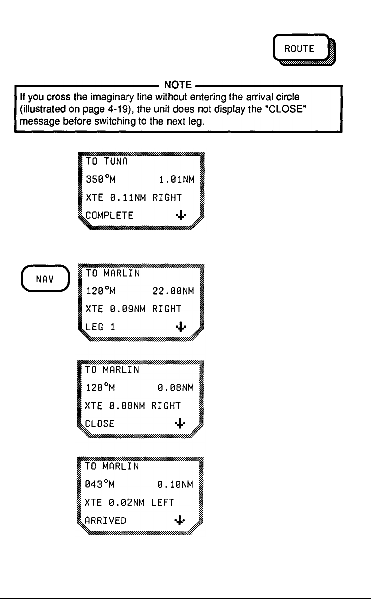
Manual Mode
When you arrive at the
final destination of the last
route leg, the unit displays
the "COMPLETE" message.
Press the NAV key after
selecting the route leg.
When you are within 500
feet (152.4 meters) of your
destination, the display
shows the "CLOSE"
message.
4-25
Imagine that a line intersects the destination
waypoint and is perpendicular to the courseline.
(See the illustration on
page 4-19.) When you
cross that line, the unit
displays the message
"ARRIVED."
Page 73

Press ROUTE, then the
RIGHT ARROW to scroll to
the next leg. Press NAV to
return to the navigation
screen.
When you reach the
route's final destination,
the unit sounds a beeper,
and the screen displays
the "COMPLETE"
message.
SETUP
SETUP is used to initialize the unit before it is used for the first time or
when it has been moved more than 300 miles (487.2 km) from where
the last fix was taken. (Although it is possible to get a position fix
without an initialized position, the unit performs better when it has been
initialized manually.) SETUP is also used to modify a configuration
item and when the unit has suffered a memory loss.
4-26
Page 74

In SETUP you can:
Initialize a position
o
Choose a position mode (2D, 3D, or Automatic)
o
Choose a local clock for time display
o
o
Set the time (local clock)
o
Choose an automatic or manual Route Mode
Select the Lat/Lon display
o
o
Select a Map Datum
o
Enter a Magnetic Variation
Select Distance and Speed Units
o
o
Select Altitude Units
o
Select the Date Order
Before pressing SETUP, take a minute or two and fill out the
on page 4-28. Keep the worksheet as a reference, so you
if the unit loses its memory and must be recustomized.
Press SETUP and then the DOWN ARROW to display the SETUP
in sequence. Use the RIGHT ARROW to toggle between the
within each feature.
worksheet
can refer to it
features
selections
Entering an Initialization Position
The initial position entered here must be correct within 300 miles
(487.2 km). If you are not sure of your position, call your local marine
electronics dealer or consult an atlas or chart.
The unit should be reinitialized if it is moved more than 300 miles
(487.2 km) from the last fix or suffers a memory loss.
4-27
Page 75

SETUP WORKSHEET
SELECT ONE OPTION FOR EACH SETUP FEATURE
(Factory defaults
MODE
are shown in bold)
❑
2D
3D
❑
Automatic
❑
TIME DISPLAY
ROUTE MODE
LAT/LON DISPLAY
MAP DATUMS
UT (UNIVERSAL
❑
COORDINATE TIME)
LOCAL (AM/PM)
❑
Automatic
❑
❑
Manual
DEGREES/MINUTES
❑
DEGREES/MINUTES
❑
/SECONDS
WGS84
USER
AUSTR
EUROP
NAD27
ALASK
MAUZ
OAHU
KAUAI
GRB36
TOKYO
WGS72
MAGNETIC VARIATION
4-28
M) AUTO MAG
❑
(
(T) TRUE
❑
(U) (USER SET)
❑
__°__ E or W (SPECIFY)
Page 76

SETUP WORKSHEET (Cont'd)
DISTANCE, SPEED UNITS
ALTITUDE UNITS
DATE ORDER
NM (nautical miles) and
❑
KNOTS (knots)
❑
Km (kilometers) and Km/HR
(kilometers per hour)
❑
MI (statute miles) and MPH
(
miles per hour)
❑
feet
❑
meters
❑
MONTH/DAY/YEAR
DAY/MONTH/YEAR
❑
4-29
Page 77

Press SETUP to see the
itial position. If a position
displayed, erase it. You
erase a position by
pressing CLEAR or by
entering the first number of
the new position; the old
position will disappear.
Enter the latitude, using
the RIGHT ARROW to
toggle between N and S. If
your latitude ends with
zeroes they do not have to
be entered; the unit will
add them. Press ENTER.
Enter the longitude, using
the RIGHT ARROW to
toggle between E and W.
Press ENTER.
incan
is
Selecting Mode and Altitude
The NAV 5000 has three modes of operation. The default mode is 2D;
2D requires a user-entered value for altitude and is used primarily at
sea. lt uses three satellites to calculate latitude and longitude. The 3D
mode uses a fourth satellite to compute your altitude for you; it is used
4-30
Page 78

primarily on land. Automatic selects 2D or 3D, according to how many
satellites are available. If the unit is intended for maritime use, we
recommend using the 2D mode for greater accuracy.
From the first SETUP
display (initial position),
press the DOWN ARROW.
Press CLEAR to erase an
existing altitude or simply
enter a new value. Enter
any new altitude. Use the
RIGHT ARROW to toggle
to a negative altitude.
Press ENTER.
If you prefer to use meters instead of feet, the unit of measure is
defined later in SETUP (see page 4-40). The NAV 5000 recalculates
stored altitudes when the unit of measure is changed. lt you know
altitude in feet, go ahead and enter it now.
Press the RIGHT ARROW
to scroll to 3D. (Altitude
can also be changed at
this screen.)
4-31
the
your
Page 79

Press the RIGHT ARROW
to go to the Automatic
mode. Remember that if
you use this mode, some
fixes may be made in 2D.
Therefore, be sure you
have entered an altitude.
Setting the Time
The unit can be operated on Universal Time (UT, formerly Greenwich
Mean Time) or local time.
The GPS satellites operate on UT, and the unit collects the current
time (in UT) from the satellites as part of the Almanac. lt is therefore
unnecessary to set time if you want to use UT. You must remember,
however, that UT displays the time and date that is current at the
me Meridian.
Pri-
If you prefer to use a local clock, you must enter the local date and
ti
me here.
From the mode/altitude
display, press the DOWN
ARROW. The screen
displays the current date
and time on the UT clock.
4-32
Page 80

To enter the local date and
ti
me, press CLEAR. Key in
the current date, in month/
day/year order. (Date order
can be changed later in
SETUP.) Press ENTER.
Press the RIGHT ARROW
change to local time.
Key in the local time (hours
and minutes), and use the
RIGHT ARROW to toggle
between AM and PM.
(Local time does not use a
24-hour clock.) Press
ENTER.
Choosing Automatic or Manual Route Modes
A route can be followed in either the automatic or manual modes.
In the automatic mode, the NAV 5000 continually updates the navigation screen. When you are within 500 feet (152.4 meters) of the
destination of a navigation leg the screen displays a "CLOSE" message. When you cross an imaginary line that runs through your destination waypoint and is perpendicular to your courseline, the unit
automatically switches to the next leg of your route.
In the manual mode, the NAV 5000 continually updates the navigation
screen, and displays the "CLOSE" message when you are within 500
feet (152.4 meters) of your destination waypoint. When you cross the
imaginary line that runs through the waypoint and is perpendicular to
the courseline, however, the unit does not advance to the next leg, but
displays an "ARRIVED" message. You must press ROUTE and the
RIGHT ARROW to advance to the next leg.
to
See page 4-18 for a more detailed description of the ROUTE function.
4-33
Page 81

To select automatic or manual route mode, use the key sequences
below. (Default is Automatic.)
From the initial time
display, press the DOWN
ARROW.
Press the RIGHT ARROW
to toggle between
automatic and manual
modes.
Choosing Lat/Lon Display
The latitude and longitude can be displayed in degrees and minutes
(
DEG/MIN) or in degrees/minutes/seconds (DEG/MIN/SEC). (Default is
DEG/MIN.)
4-34
From the route mode
display, press the DOWN
ARROW.
Use the RIGHT ARROW to
toggle between Deg/Min
and Deg/Min/Sec.
Page 82
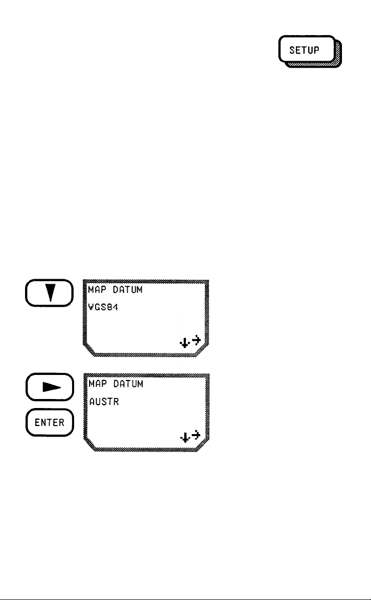
Selecting a Map Datum
The NAV 5000 provides 12 geodetic map datums for use with charts
and maps worldwide. The unit also allows you to enter manually
any
map datum not currently in the unit's memory.
A datum refers to a mathematical model of the earth. The latitude and
longitude of a position differs from one model (datum) to another. lt is
therefore important to know which map datum you will be using if you
want to relate your position information to a chart, since using a
different datum may result in positioning errors of up to 1968.5 feet
(600 meters) when compared with the chart.
The Map Datum feature allows you to operate the NAV 5000 on a
datum that corresponds to the charts you are using. Which datum your
chart uses can usually be found in the legend.
From the Lat/Lon display,
press the DOWN ARROW.
4-35
Use the RIGHT ARROW to
scroll through the available
datums until you find one
that corresponds to your
chart. Press ENTER.
Page 83

Setting a User-Entered Datum
If your Chart uses a datum that is not included in the choices listed on
the SETUP worksheet, you can use a user-entered datum. Refer to
Appendix 2 for the constants to convert the most common local datums
to WGS84.
From the LAT/LON display,
press the DOWN ARROW.
Press the RIGHT ARROW
until this message appears.
4-36
Page 84

4-37
Page 85

Press ENTER, then enter
Press ENTER again to
store the values entered.
Magnetic Variation Display
Select one of the three available heading and bearing types for all
displays and entries.
Auto Mag (M) lncludes an automatic adjustment for variation
by the NAV 5000. (Default)
True (T)
Set (U)
No magnetic adjustment in readout
A constant user-entered adjustment
From the Map Datum
display, press the DOWN
ARROW to reach this
display.
Use the RIGHT ARROW to
toggle between the choices
listed above. If you select
User Set (U), the screen
displays the last entered
value.
4-38
Page 86

DIstance/Speed Units
To change the value
displayed, either press
CLEAR or begin entering
numbers to clear the
display. Enter the constant
compass error in degrees
and minutes. Use the
RIGHT ARROW to toggle
between East and
West.
Press ENTER and the
display returns to the
magnetic variation display.
4-39
From the magnetic variation display, press the
DOWN ARROW. The
currently selected unit of
measurement for distance
and speed is displayed.
Page 87

Altitude Units
Use the RIGHT ARROW to
toggle between nautical
miles and knots, kilometers
and kilometers per hour,
and statute miles and miles
per hour.
From the distance/speed
display, press the DOWN
ARROW to view altitude
units. The default unit of
measurement is feet.
Use the RIGHT ARROW to
toggle between feet and
meters.
Changing altitude units affects all displays where altitude is shown.
The unit recalculates all altitude measurements to the new unit of
measure.
4-40
Page 88

Date Order
From the altitude display,
press the DOWN ARROW
to view the date order.
Use the RIGHT ARROW to
change the date order.
Press the DOWN ARROW to return to the first SETUP display. Press
any function key other than SETUP, DOWN ARROW, or RIGHT
ARROW to exit SETUP.
VELOCITY
The VELOCITY key displays information about your rate and direction
of travel. (Speed Over Ground and ground course). This information is
available only in continuous operation and when your speed exceeds
0.2 knots. (Speeds greater than 951 mph/1529.5 kph/826.73 knots
cannot be measured.)
Press VEL.
4-41
Page 89

WAYPOINT
The WAYPOINT (WPT) key lets you enter up to 100 positions in the
unit's memory by saving a current position, a last fix, or a fix backup, or
by manually entering a position. Waypoints can also be viewed,
deleted, and renamed.
Waypoints are stored in alphanumeric order.
Saving Positions as Waypoints
Use the following key sequence to save a position as a waypoint.
Locate the position fix you
want to save.
Press the ENTER key. The
cursor goes to the upper
left corner on the message
display.
4-42
Page 90

Name the waypoint. Enter
one to six characters as
described in "Entering
Data" on page 2-14. Press
ENTER.
OR
Press ENTER to name the
waypoint automatically.
If the name you chose is
already being used, this
message appears. Press
ENTER and key in another
name.
4-43
If you do not choose a
name for the waypoint, the
NAV 5000 generates one.
Unit-generated names are
in the format WPTxxx,
where xxx represents
numbers 001 through 099.
Waypoints are numbered
in sequence.
Page 91

To allow the unit to name
the waypoint, simply press
ENTER again.
Once the position has been saved, date/time message can be accessed by pressing the DOWN ARROW. Use the RIGHT ARROW to
display waypoints in alphabetical order .
Entering Waypoints Manually
Use the following key sequence to enter a waypoint manually.
Press the WPT key.
Press the ENTER key
once.
TUNA
Enter a one- to sixcharacter waypoint name
from the alphanumeric
keypad, or press ENTER
again to name the
waypoint automatically.
4-44
Page 92

This message appears if
the name you chose is
already being used. Press
ENTER and key in.
Key in the latitude. Press
ENTER. Use the RIGHT
ARROW to toggle between
N (north) and S (south).
Key in the longitude. Use
the RIGHT ARROW to
toggle between W (west)
and E (east). Press
ENTER.
4-45
Page 93

Viewing Stored Waypoints
Key in the altitude. Use the
RIGHT ARROW to toggle
between positive and
negative values (above
and below sea level).
Press ENTER.
Press ENTER again to
store this information.
When ENTER has been
pressed, the DOWN
ARROW appears on the
display.
lf this message appears,
there is no room to store
another waypoint. You
must delete a waypoint
before another can be
stored. See "Clearing
Waypoints" below.
Use the following key sequence to access and view a waypoint.
Press the WPT key.
4-46
Page 94

Press the RIGHT ARROW
to scroll through the stored
waypoints. You can also
key in all or part of a
waypoint name and press
ENTER. Use the RIGHT
ARROW to continue to
scroll.
Press the DOWN ARROW
to see the datum, date,
and time of the position fix
for TUNA.
Press the DOWN ARROW
again to see the satellite
signal quality and
geometric quality of the fix.
lf a waypoint was entered
manually, no values will
be displayed for satellite
signal quality and
geometric quality.
Renaming Waypoints
To rename a waypoint, retrieve it as described in "Viewing a
Waypoint." From any of the waypoint message displays, press ENTER. Enter the new name, and press ENTER again.
Waypoints that are assigned to a route cannot be renamed. This
includes the waypoint "start".
4-47
Page 95

Waypoint "start" can, however, be copied. Retrieve the waypoint and
rename it as described above. The unit copies the position data from
"start" to the new waypoint name. "Start" is untouched until a new route
is entered.
Clearing a Waypoint
Use the following key sequence to delete a waypoint from the unit's
memory.
Locate and retrieve the
waypoint, as described in
"Viewing a Waypoint."
CLEAR. The display
the message
illustrated.
Press
shows
To continue and erase the waypoint, press CLEAR again.
To abort and keep the waypoint, press any function key.
To clear
all
waypoints, use AUX 10.
4-48
Page 96

CHAPTER 5
AUXILIARY FUNCTIONS
In addition to the 9 function keys described in Chapter 4, the NAV 5000
has 11 auxiliary functions. The Auxiliary Functions give you additional
information and control over how the unit displays information.
The Auxiliary Functions can be accessed two ways.
Press AUX and the
number of the Auxiliary
Function you want to
access, followed by
ENTER.
OR
Press AUX and use the
RIGHT ARROW to scroll
through the Auxiliary
Functions until you see the
one you want. Then press
ENTER.
This chapter is arranged in numerical order; for your convenience, a
table at the end of the chapter arranges the functions in alphabetical
order.
5-1
Page 97

AUX 1- RECEIVER STATUS SCREEN
The receiver status screen allows you to monitor the search, acquisition, and ranging of satellites that are visible and may be used for a
position fix.
The receiver status display appears when POS is pressed. You can
also go to this display manually when you want to know which satellites are being tracked and the signal quality from each satellite. This
can be helpful if you are having difficulty getting a position fix, especially if you think the signals may be blocked.
Press AUX, 1, and ENTER
(or AUX and the RIGHT
ARROW).
Each column on the display represents a channel; the unit searches for
the five satellites identified on the first line simultaneously. The second
line monitors the search and acquisition of the satellites. The third line
identifies the satellites that have been or will be used for the position
fix, and which satellites the unit has collected Ephemeris data from.
(Refer to the Illustration below.)
READING THE RECEIVER STATUS SCREEN
5-2
Page 98

The mode of operation (2D or 3D) is indicated by the number of
satellites marked with an asterisk. On the sample above, 4 satellites
have asterisks, therefore, the position fix will be in 3D. If the unit were
in 2D, 3 satellites would have asterisks, and only 4 channels would be
displayed.
AUX 2 - DISPLAY CONTROL
The Display Control function allows you to change the brightness of
the display.
Press AUX, 2, and ENTER
(or press AUX once and
RIGHT ARROW twice)
view the Display Control
screen.
Press LIGHT to backlight
the display. Press the
RIGHT ARROW to change
the display brightness.
to
the
The possible levels of brightness are 1 through 15. Each time the
RIGHT ARROW is pressed, the brightness setting increases by one. At
15, the value rotates back to 1. (The default setting is 15.)
Once set, the values chosen remain unchanged until reset or the unit's
memory is lost or cleared.
AUX 3 - SATELLITE STATUS
Satellite Status (referred to as "Sat Status" throughout this guide)
provides specific information on the satellites used by GPS. Sat Status
can give you the following information:
which satellites are listed as being healthy by the GPS system
o
operators.
the elevation and azimuth of the satellites that are above the
o
horizon.
5-3
Page 99

satellites with weak SQs or set temporarily unusable by the
o
system operators.
the current status of every satellite in the system.
o
The satellite status display includes one of the following messages:
GPS
ON:
TEMP OFF:
OFF:
Satellites that are listed in the Almanac as being unhealthy by the GPS
operators are not listed in Sat Status. Satellites are identified
by a pseudorange number (PRN), which is used by the government to
the satellites.
the satellite is operating and is healthy.
the unit is temporarily ignoring this satellite.
Usually a satellite is being ignored because,
after three tries, the unit was unable to find it.
This happens when a satellite is hidden from
view by buildings or other large obstacles. The
will be temporarily off until the unit is
turned off and back on, or until the satellite is
the fifth channel.
the unit has been instructed to ignore this
satellite by the user, perhaps because its SQ
is very low. The satellite remains off until it is reset.
located by
Press AUX, 3, and ENTER
(or press AUX once and
RIGHT ARROW three
mes) to reach the Sat
ti
Status display. The first
display is the message
POS.
satellite
system
identity
the
5-4
You can analyze your
current position or press
the RIGHT ARROW to
analyze a waypoint.
Page 100

Press ENTER to accept
the displayed position. The
current date and time is
displayed. lt you want to
reset the date and time,
you can do this now.
Press ENTER again. The
unit computes and displays
the current status of
all healthy satellites in
numerical order. Elevation
and azimuth is displayed
for satellites that are above
the horizon. An SQ is
when the satellite
was used to
a position
Press the DOWN ARROW
to display the status of the
next satellite.
recently obtain
fix.
shown
displayed
5-5
Press the RIGHT ARROW
to toggle between ON and
OFF for this satellite. Press
the DOWN ARROW to
view Sat Status for the
next satellite.
 Loading...