

Page 1

CAR AUDIO EQUIPMENT
®
42.29
Owner`s Manual
Bedienungsanleitung
Manuel d`Emploi
Manuale di Instruzioni
Manual de Instrucciones
Page 2

CONTENTS / INHALT / TABLE DE MATIERES / INDICE / ÌNDICE
• CONNECTIONS / ANSCHLUSSE / CONNEXIONES /
COLLEGAMENTI / CONEXIONES . . . . . . . . . . . . . . . . . . . . . . . . . . . . . . . . . . . . . . . . . . . II
• SYSTEM CHART / SYSTEM-DIAGRAMM / EXEMPLES DE SYSTEME /
DIAGRAMMA DI SISTEMA / DIAGRAMMA DEL SISTEMA . . . . . . . . . . . . . . . . . . . . . . . . III
• TABLE OF COMPONENT VALUES . . . . . . . . . . . . . . . . . . . . . . . . . . . . . . . . . . . . . . . . . . IV
“ ENGLISH”
INTRODUCTION . . . . . . . . . . . . . . . . . . . . . . . . . . . . . . . . . . . . . . . . . . . . . . . . . . . . . . . . . . . 7
PRECAUTIONS . . . . . . . . . . . . . . . . . . . . . . . . . . . . . . . . . . . . . . . . . . . . . . . . . . . . . . . . . . . . 7
FEATURES. . . . . . . . . . . . . . . . . . . . . . . . . . . . . . . . . . . . . . . . . . . . . . . . . . . . . . . . . . . . . . . . 7
CONTROL AND INICATORS. . . . . . . . . . . . . . . . . . . . . . . . . . . . . . . . . . . . . . . . . . . . . . . . . 8-9
TECHNICAL DATA . . . . . . . . . . . . . . . . . . . . . . . . . . . . . . . . . . . . . . . . . . . . . . . . . . . . . . . . . 10
“ DEUTSCH ”
INTRODUCTION. . . . . . . . . . . . . . . . . . . . . . . . . . . . . . . . . . . . . . . . . . . . . . . . . . . . . . . . . . . 11
PRECAUTIONS . . . . . . . . . . . . . . . . . . . . . . . . . . . . . . . . . . . . . . . . . . . . . . . . . . . . . . . . . . . 11
EIGENSCHAFTEN . . . . . . . . . . . . . . . . . . . . . . . . . . . . . . . . . . . . . . . . . . . . . . . . . . . . . . . . . 11
EINSTELLUNGEN UND ANZEIGEN . . . . . . . . . . . . . . . . . . . . . . . . . . . . . . . . . . . . . . . . . 12-13
TECHNISCHE DATEN . . . . . . . . . . . . . . . . . . . . . . . . . . . . . . . . . . . . . . . . . . . . . . . . . . . . . . 14
“ FRANCAIS ”
INTRODUCTION. . . . . . . . . . . . . . . . . . . . . . . . . . . . . . . . . . . . . . . . . . . . . . . . . . . . . . . . . . . 15
PRECAUTIONS . . . . . . . . . . . . . . . . . . . . . . . . . . . . . . . . . . . . . . . . . . . . . . . . . . . . . . . . . . . 15
CARACTERISTIQUES . . . . . . . . . . . . . . . . . . . . . . . . . . . . . . . . . . . . . . . . . . . . . . . . . . . . . . 15
CONTROLES ET INDICATEURS . . . . . . . . . . . . . . . . . . . . . . . . . . . . . . . . . . . . . . . . . . . 16-17
DONNEES TECHNIQUES . . . . . . . . . . . . . . . . . . . . . . . . . . . . . . . . . . . . . . . . . . . . . . . . . . . 18
“ ITALIANO ”
INTRODUZIONE. . . . . . . . . . . . . . . . . . . . . . . . . . . . . . . . . . . . . . . . . . . . . . . . . . . . . . . . . . . 19
PRECAUZIONI . . . . . . . . . . . . . . . . . . . . . . . . . . . . . . . . . . . . . . . . . . . . . . . . . . . . . . . . . . . . 19
CARATTERISTICHE. . . . . . . . . . . . . . . . . . . . . . . . . . . . . . . . . . . . . . . . . . . . . . . . . . . . . . . . 19
CONTROLLI & INDICATORI . . . . . . . . . . . . . . . . . . . . . . . . . . . . . . . . . . . . . . . . . . . . . . . 20-21
DATI TECNICI. . . . . . . . . . . . . . . . . . . . . . . . . . . . . . . . . . . . . . . . . . . . . . . . . . . . . . . . . . . . . 22
“ ESPAÑOL ”
INTRODUCTION. . . . . . . . . . . . . . . . . . . . . . . . . . . . . . . . . . . . . . . . . . . . . . . . . . . . . . . . . . . 23
PRECAUTIONS . . . . . . . . . . . . . . . . . . . . . . . . . . . . . . . . . . . . . . . . . . . . . . . . . . . . . . . . . . . 23
CARACTERÍSTICAS . . . . . . . . . . . . . . . . . . . . . . . . . . . . . . . . . . . . . . . . . . . . . . . . . . . . . . . 23
CONTROLES & INDICADORES . . . . . . . . . . . . . . . . . . . . . . . . . . . . . . . . . . . . . . . . . . . . 24-25
DATOS TÉCNICOS. . . . . . . . . . . . . . . . . . . . . . . . . . . . . . . . . . . . . . . . . . . . . . . . . . . . . . . . . 26
I
Page 3
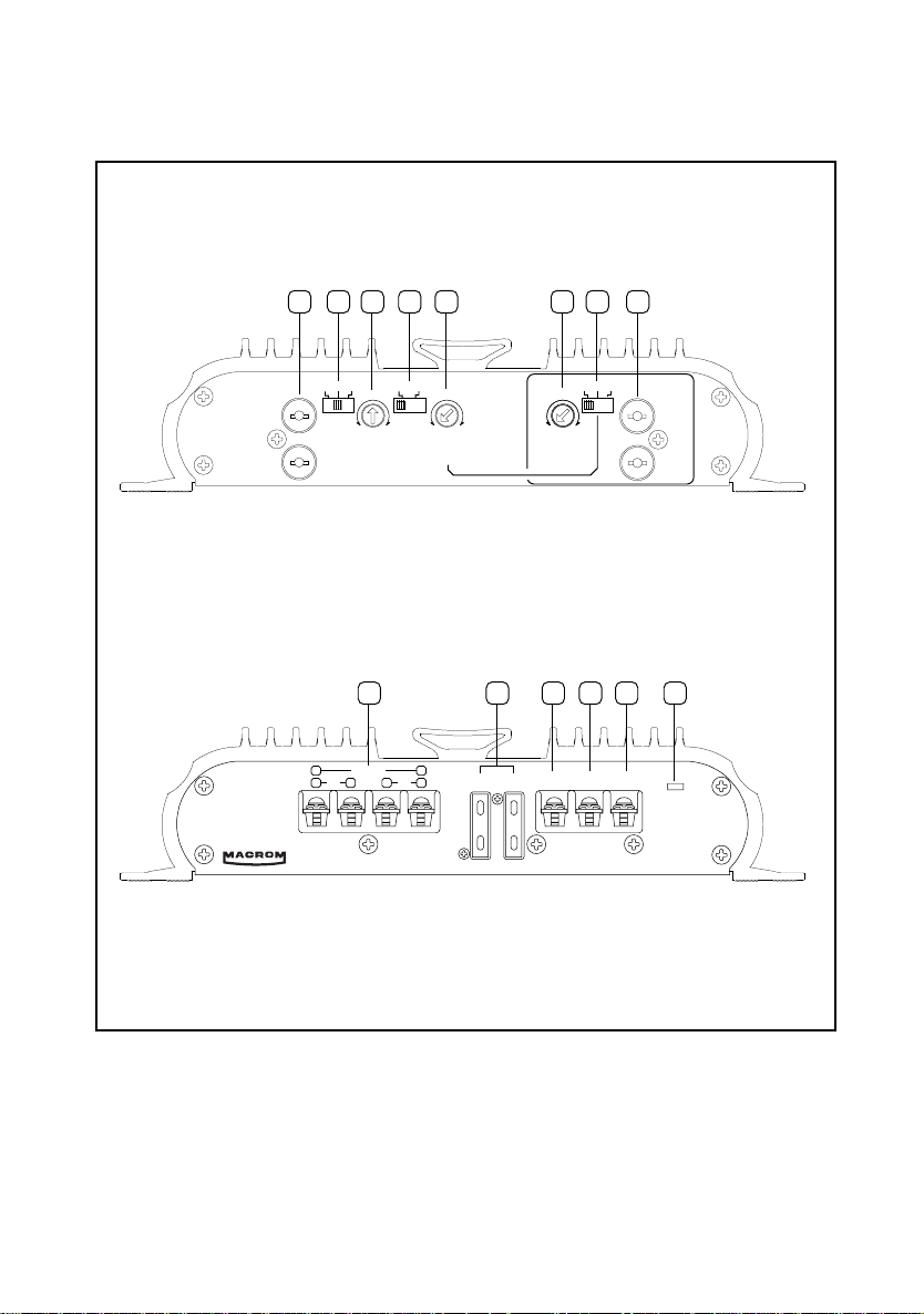
Input
Left
Right
L(mono) ST L+R
Gain
Control
2V 0,2V
0,5V
30 600
150 Hz
Pre Output
Left
30 600
150 Hz
Flat Low
Low
Pass
Filter
Right
Flat Low High
High
Pass
Filter
ChecK Control
R
-
+
L
-
+
Fuse + Batt GND Remote
42.29 Power Amplifier
-
+
Bridged
Fuse
1 2 3 4 5 6 7 8
9 10 11 12 13 14
CONNECTIONS / ANSCHLUSSE / CONNEXIONES /
COLLEGAMENTI / CONEXIONES
II
Page 4
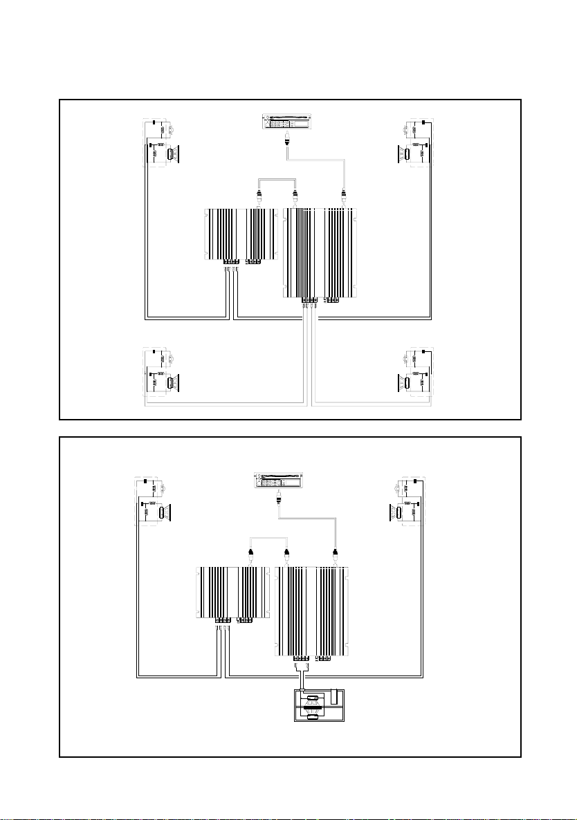
42.29
42.26
SYSTEM CHART / SYSTEM-DIAGRAMM / EXEMPLES DE SYSTEME /
DIAGRAMMA DI SISTEMA / DIAGRAMA DEL SISTEMA
42.26
42.29
III
Page 5
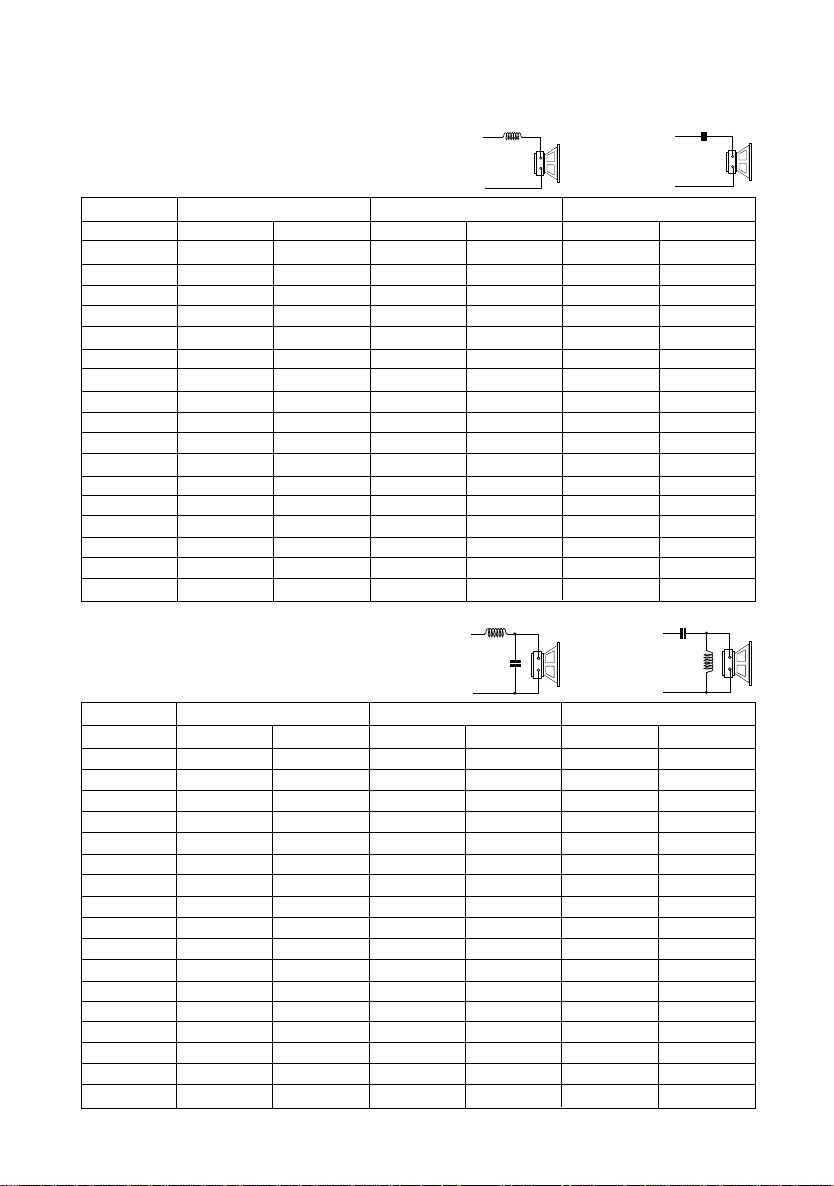
TABLE OF COMPONENT VALUES
+
-
+
-
+
-
+
-
6 dB/Octave High and low Pass Filter
L1
Low Pass
Frequency 2 Ohm 4 Ohm 8 Ohm
Hz L1 C1 L1 C1 L1 C1
50 6.4 mH 1600 µF 12.8 mH 800 µF 25.4 mH 400 µF
80 4.1 mH 1000 µF 8.2 mH 500 µF 16 mH 250 µF
100 3.1 mH 800 µF 6.2 mH 400 µF 12 mH 200 µF
130 2.4 mH 600 µF 4.7 mH 300 µF 10 mH 150 µF
200 1.6 mH 400 µF 3.3 mH 200 µF 6.8 mH 100 µF
400 0.8 mH 200 µF 1.6 mH 100 µF 3.3 mH 50 µF
600 0.5 mH 136 µF 1.0 mH 68 µF 2.0 mH 33 µF
800 0.41 mH 100 µF 0.82 mH 50 µF 1.6 mH 25 µF
1000 0.31 mH 78 µF 0.62 mH 39 µF 1.2 mH 20 µF
1200 0.25 mH 66 µF 0.51 mH 33 µF 1.0 mH 16 µF
1800 0.16 mH 44 µF 0.33 mH 22 µF 0.68 mH 10 µF
4000 0.08 mH 20 µF 0.16 mH 10 µF 0.33 mH 5 µF
5000 0.06 mH 16 µF 0.12 mH 8 µF 0.25 mH 4 µF
6000 0.05 mH 14 µF 0.10 mH 6.8 µF 0.20 mH 3.3 µF
7000 0.045 mH 11 µF 0.09 mH 6 µF 0.18 mH 3.0 µF
8000 0.04 mH 10 µF 0.08 mH 5 µF 0.19 mH 2.2 µF
10000 0.03 mH 8 µF 0.06 mH 4 µF 0.13 mH 2 µF
12 dB/Octave High and low Pass Filter
L1
C1
Low Pass
HighPass
Frequency 2 Ohm 4 Ohm 8 Ohm
Hz L1 C1 L1 C1 L1 C1
50 9 mH 1100 µF 18 mH 550 µF 36 mH 270 µF
80 5.5 mH 680 µF 11 mH 330 µF 22 mH 180 µF
100 4.7 mH 560 µF 9.1 mH 270 µF 18 mH 150 µF
130 3.3 mH 400 µF 6.8 mH 200 µF 15 mH 100 µF
200 2.2 mH 300 µF 4.7 mH 150 µF 9.1 mH 75 µF
400 1.1 mH 150 µF 2.2 mH 68 µF 4.7 mH 33 µF
600 0.75 mH 100 µF 1.5 mH 47 µF 3.0 mH 27 µF
800 0.50 mH 68 µF 1.0 mH 33 µF 2.0 mH 15 µF
1000 0.47 mH 50 µF 0.91 mH 27 µF 1.8 mH 13 µF
1200 0.33 mH 44 µF 0.75 mH 22 µF 1.5 mH 11 µF
1800 0.27 mH 30 µF 0.50 mH 15 µF 1.0 mH 6.8 µF
4000 0.10 mH 15 µF 0.22 mH 6.8 µF 0.47 mH 3.3 µF
5000 0.09 mH 11 µF 0.18 mH 5 µF 0.36 mH 3 µF
6000 0.075 mH 10 µF 0.15 mH 4.7 µF 0.33 mH 2.2 µF
7000 0.065 mH 8 µF 0.13 mH 4 µF 0.26 mH 2 µF
8000 0.06 mH 7 µF 0.11 mH 3.3 µF 0.23 mH 2 µF
10000 0.045 mH 6 µF 0.082 mH 3 µF 0.18 mH 1.2 µF
C1
HighPass
C1
L1
IV
Page 6

INTRODUCTION
The name of MACROM has always been the synonym of tradition, of a European acoustic and
musical tradition in the pursue of the topmost sound quality and the fact that you chose to buy
this product makes it clear that you due agree with us. With the help of this manual you will be
able to maximise the enjoyment that you will get out of your new 42.29 Mono Amplifier.
This amplifier incorporates many advanced technical features and performances. Therefore, it
is essential that all signals sources, speakers and interconnection devices are of the highest
sonic quality. We strongly recommend the use of MACROM head units, power amplifiers,
speaker systems, high-quality interconnection cables and accessories, because the
integration of all these products is very complex. We therefore advise that you have installed
the 42.29 by your MACROM dealer.
This product has no user-adjustable controls; read this manual carefully in order to become
well acquainted with all the special features and functions of your new MACROM 42.29. Do
not hesitate to contact your MACROM dealer should you have any problem.
PRECAUTIONS
1. The unit may be damaged by wrong lead connection, therefore read carefully the
instructions of this manual for the correct connection of the leads.
2. The last lead to be connected is the one to the positive (+) terminal of the battery; connect
this lead only after having completed and checked all other connections.
3. Be sure to install the crossover in a position with good air circulation and good heat
dissipation.
4. In case of fuse replacement make sure to replace it with a fuse of the same amperage. If
fuses blow more than once, carefully check all electrical connections. Also have your car’s
voltage regulator checked. Do not attempt to repair the unit yourself. If repairs are ever
needed, take the unit to your MACROM dealer or to your nearest MACROM service
station.
5. In order to get the best possible performance from this unit, make sure that the
temperature inside your car is within the range of -10° C and +60° C before you switch the
unit on. Good air circulation is essential to prevent heat build-up inside the unit.
FEATURES
• LOW-PASS FILTER THAT CAN BE SET AT THE END SECTION
• PRE-OUTPUT WITH “FLAT, HIGH- OR LOW-PASS FILTER” SELECTOR
• CONTINUOUS AND INDEPENDENT ADJUSTMENTS OF THE FREQUENCY CUTOFFS
• INPUT MODE SELECTOR: MONO, STEREO OR MIX
• CONTINUOUS ADJUSTMENT OF INPUT SENSITIVITY
• MOS-FET POWER SUPPLY
• “CHECK CONTROL” STATE INDICATOR
• REMOTE ON AND OFF
• GOLD-PLATED RCA INPUT CONNECTIONS
• PROFESSIONAL GOLD-PLATED SCREW-TYPE SUPPLY TERMINALS
6
Page 7
CONTROLS AND INDICATORS
600Hz30Hz
150Hz
33Hz
36Hz
45Hz
70Hz
100Hz 250Hz
340Hz
470Hz
520Hz
580Hz
Flat Low
Flat Low
20Hz 20kHz
20Hz 30>600Hz
L(mono) ST L+R
L(mono) ST L+R
L(mono) ST L+R
20Hz 20kHz
20Hz 30>600Hz
Flat Low High
Flat Low High
Flat Low High
30>600Hz 20kHz
1 • RCA INPUT CONNECTORS: connect the pre-output leads of the head
unit to the input connectors.
2 • INPUT MODE SELECTOR: allows to select the amplifier’s
configuration as follows:
a) STEREO “ST” when the amplifier is used as a two-channel stereo
system (right + left);
b) MONO (L mono) when the amplifier is driven by one input signal “Left”
and outputs are mono-bridged.
NOTE: in this configuration, no signal is present at the “Right” pre-output
RCA output connection;
c) MIX “L+R”: when the amplifier is designed to drive one or more subwoofers according to the
1-, 2- or 3-channel configurations. Thus, the inputs signals will be blended into one signal.
NOTE: anyway, the signals present at the Pre-output outputs will always be stereo.
3 • INPUT GAIN ADJUSTMENT CONTROL: input sensitivity ranges from 200 mV to 2V.
Set the mid position for all MACROM units.
In case the amplifier is to be connected to a head unit that is not of MACROM make but is
fitted with preamplified RCA outputs, proceed as follows:
a) set the volume control of your head unit to 3/4 of maximum ouput
level;
b) set the input gain control to the point where the maximum sound
level with no distortion is obtained.
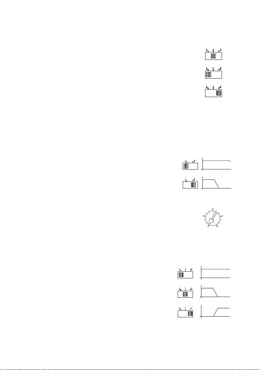
4 • LOW-PASS SELECTOR SWITCH: it allows to select the
amplifier’s output mode by activating the Low-Pass crossover.
a) Flat: the amplifier reproduces the whole range of frequencies from 20 Hz
to 20kHz
b) Low: the amplifier reproduces low frequencies only.
5 • LOW-PASS FREQUENCY ADJUSTMENT: allows the continuous
adjustment of the low-pass frequency between 30 and 600 Hz, to
determine the end point of the audio range present at the amplifier’s
outputs and at the Pre-output outputs should the low-pass filter be selected.
6 • HI-PASS FREQUENCY ADJUSTMENT: allows the continuous adjustment of the high-pass
frequency between 30 and 600 Hz, to determine the starting
value of the audio range present at the Pre-Output outputs.
7 • PRE-OUTPUT SELECTOR SWITCH: allows to select the
Pre-output output mode as follows:
a) FLAT: a signal having the same form and amplitude as the
input signal is present at the Pre-output outputs;
b) LOW: a low-pass signal is present at the Pre-output outputs
in order to drive an additional amplifier. Frequencies can be
adjusted by means of the LOW-PASS FREQUENCY “5”
control;
c) HIGH: a high-pass signal is present at the Pre-output outputs in order to drive an additional
amplifier. Frequencies can be adjusted by means of the HIGH-PASS FREQUENCY “6” control.
7
Page 8
CONTROLS AND INDICATORS
++
+
BRIDGED
L R
++
+
BRIDGED
L R
++
+
BRIDGED
L R
8 • PRE-OUTPUT RCA OUTPUT CONNECTORS: connect to an additional amplifier to be
used according to the mode previously selected.
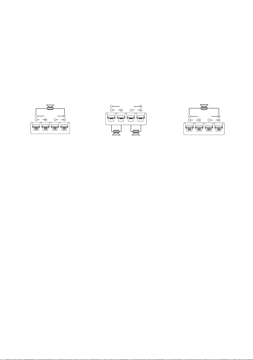
9 • SPEAKER CONNECTOR: outputs for speakers connection. The amplifier allows to
connect speakers with minimum 1-ohm impedance per channel in stereo configuration and
with minimum 2-ohm impedance in mono-bridged configuration. Should the 3-channel
configuration be used, total impedance must not exceed the minimum 2-ohm value.
Be sure to keep the right polarity and phase in connecting the speakers. Avoid any contact
between poorly insulated wires and the car’s ground or metal pieces and between the wires
themselves.
3-channel configuration 2-channel configuration 1-channel configuration
10 • FUSE: in case of fuse replacement make sure to use fuses of the same amperage. The
use of fuses with the wrong amperage may seriously damage the components of the unit.
11 • BAT + CONNECTOR: to be connected directly to battery + by means of a fuse located
close to the battery itself. Utilize a cable having an adequate section. Do not connect this
cable to the car’s electrical system wiring (eg.: dome-light circuit, car radio etc.)
12 • GND CONNECTOR: connect the ground terminal to a clean base metal part of the
vehicle chassis (if possibile, to an existing screw). Utilize a cable having an adequate section.
13 • REMOTE-ON CONNECTOR: to be connected either to the remote switch-on output lead
or to the output lead of the power antenna coming from the head unit. As a resul, the 42.29 will
be switched on and off simultaneously with the head unit.
14 • CHECK CONTROL LED: this led shows the amplifier’s status of operation:
WHITE: the unit is off
GREEN: the unit is working OK
RED: the unit has entered the protection mode
The 42.29 is equipped with three different protection devices:
Overheating: in case of wrong installation the unit enters the protection mode before being
damaged. As soon as the temperature returns to normal values, the unit resumes normal
operation.
Overload: if several speakers are connected to the amplifier and the total impedance
decreases below the allowable threshold (0.5 - 1 ohm), the amplifier enters automatically the
protection mode to avoid any damage. To restore normal operation the head unit has to be
switched off and then on again.
Output short circuit: in case of a short circuit at the speakers outputs, the unit enters the
protection mode to avoid serious damage to the end stage transistors. Normal operation is
restored by eliminating the short circuit and by switching on the head unit again.
8
Page 9

TECHNICAL DATA
Maximum power 450 Watt
Nominal RMS 4 Ohm 90 Watt x 2
Nominal RMS 2 Ohm 180 Watt x 2
Nominal RMS mono-bridged 4 Ohm 350 Watt x 1
Low-Pass control (amplifier section or
High-Pass control (Pre-output section) 30-600 Hz at 12 dB/oct
Pre-output sensitivity 1-1
Frequency response ± 1 dB 10 - 50,000 Hz
Total harmonic distortion 0.08%
S/N (signal-to-noise ratio) IHFA-weighed >100 dB
Input sensitivity/impedance 200-2000 mV/22 kOhm
Speaker impedance
stereo 1 Ohm min
mono bridged 2 Ohm min
Power supply 14.4 V DC (11-16 V allowed)
Weight 2,65 kg
Size 217(l) x 49(h) x 280(d) mm
Pre-output section) 30-600 Hz at 12 dB/oct
Due to continuing improvement, the features and the design are subject to change without
notice.
9
Page 10

EINFÜHRUNG
Der Name MACROM ist seit jeher Synonym von Tradition, einer europäischen Tradition von
Sound und Musik, die die beste Tonqualität zum höchsten ZIel gesetzt hat. Die Tatsache, daß
Sie sich für dieses Produkt entschieden haben, beweist, daß auch Sie so denken. Diese
Bedienungsanleitung wird Ihnen dabei helfen, die vielen Eigenschaften dieser neuen Mono
Endstufe 42.29 zu entdecken und vorteilhaft einzusetzen.
Diese Endstufe schließt eine ganze Reihe von besonderen technischen Eigenschaften und
Leistungsmerkmalen ein; aus diesem Grund ist es besonders wichtig, daß alle Signalquellen,
Lautsprecher und Anschlußgeräte von höchster Qualität sind. Wir empfehlen die Verwendung
eines Hauptgeräts, einer Leistungs-Endstufe, von Lautsprechersystemen, Verbindungskabeln
und Zubehör von MACROM, die den höchsten Qualitätsanforderungen entsprechen, denn die
Verbindung dieser Geräte ist äußerst komplex. Aus diesem Grund raten wir, die Endstufe
42.29 von Ihrem MACROM-Vertragshändler installieren zu lassen.
Diese Endstufe von MACROM hat keine Einstellungen und Regelungen, die vom Anwender
benutzt werden können. Lesen Sie diese Bedienungsanleitung sehr sorgfältig, um sich mit den
besonderen Eigenschaften und Funktionen Ihrer neuen Endstufe 42.29 von MACROM
vertraut zu machen. Wenden Sie sich im Zweifelsfalle vertrauensvoll an Ihren MACROMVertragshändler.
VORSICHTSMAßNAHMEN
1. Jegliche falsche Verbindung könnte das Gerät beschädigen. Lesen Sie aufmerksam die
Anleitungen für den Kabelanschluß durch.
2. Das Batteriekabel zuletzt an den Pluspol (+) der Batterie anschließen und nur, nachdem
alle anderen Anschlüsse ausgeführt worden sind.
3. Man vergewissere sich, daß die elektronische Frequenzweiche an einer Stelle installiert
wird, wo gute Luftzirkulation und eine gute Wärmeabgabe gewährleistet sind.
4. Die Sicherungen müssen immer durch Sicherungen mit der gleichen Amperezahl ersetzt
werden, um schwere Beschädigungen der Gerätekomponenten zu vermeiden. Man lasse
bei mehrmaligem Durchbrennen der Sicherungen die Lichtmaschine des Wagens
überprüfen. Das Gerät niemals selber reparieren, sondern jegliche Reparatur Ihrem
MACROM-Vertragshändler oder der nächsten MACROM-Dienststelle übergeben.
5. Um die besten Leistungen zu erzielen sollte die Temperatur im Wageninnenraum zwischen
-10° C und +60° C liegen, bevor man das Gerät einschaltet.
EIne gute Lüftung des Wageninnenraums ist erforderlich, um die Überhitzung der inneren
Stromkreise des Gerätes zu vermeiden.
EIGENSCHAFTEN
• LOW-PASS-FILTER IN DER ENDSTUFE
• VORAUSGANG MIT FLAT-, HIGH- ODER LOW-PASS-FILTER-EINSTELLUNG
• STUFENLOSE, UNABHÄNGIGE TRENNFREQUENZREGELUNG
• WAHLSCHALTER FÜR DEN EINGANGSMODUS, MONO, STEREO ODER MIX
• STUFENLOSE EINGANGSEMPFINDLICHKEITSREGELUNG
• MOS-FET-SPEISUNG
• “CHECK CONTROL”-STATUSANZEIGE
• REMOTE-EIN- UND -AUSSCHALTUNG
• VERGOLDETE RCA-EINGANGSANSCHLÜSSE
• VERGOLDETE, PROFESSIONELLE SCHRAUBANSCHLÜSSE
10
Page 11

EINSTELLUNGEN UND ANZEIGEN
600Hz30Hz
150Hz
33Hz
36Hz
45Hz
70Hz
100Hz 250Hz
340Hz
470Hz
520Hz
580Hz
Flat Low
Flat Low
20Hz 20kHz
20Hz 30>600Hz
L(mono) ST L+R
L(mono) ST L+R
L(mono) ST L+R
20Hz 20kHz
20Hz 30>600Hz
Flat Low High
Flat Low High
Flat Low High
30>600Hz 20kHz
1 • RCA-EINGANGSVEBINDER: Die Ausgangskabel ´Pre´ Ihres
Hauptgerätes an die Eingangsverbinder anschließen
2 • WAHLSCHALTER FÜR DEN EINGANGSMODUS:
Dient zur Einstellung der Verstärkerkonfiguration wie folgt:
a) STEREO “ST”, falls er als Verstärker mit zwei Stereokanälen “links und
rechts” verwendet wird.
b) MONO “L mono”, wenn er von nur einem Eingangssignal “Left”
gesteuert wird und die Ausgänge in Mono überbrückt sind. ANMERKUNG: Bei dieser Variante
ist kein Vorausgangssignal “Right” am RCA-Anschluß vorhanden.
c) MIX “L+R”, falls er zur Steuerung eines oder mehrerer Subwoofer dient, bei denen die
Konfiguration mit 1, 2 oder 3 Ausgangskanälen verwendet wird. Die Eingangssignale werden
dann miteinander zu einem einzigen Signal summiert.
ANMERKUNG: An den Vorausgängen liegen in jedem Fall Stereo-Signale an.
3 • EINGANGSGEWINNREGELUNG: Die Eingangsempfindlichkeit liegt zwischen 200mV und
2V. Bei allen Macrom-Geräten muß die mittlere Position eingestellt
werden. Falls Sie ein anderes Gerät anschließen, das mit
vorverstärkten RCA-Ausgängen ausgestattet ist, muß wie folgt
vorgegangen werden:
a) Den Lautstärkeregler Ihres Geräts auf 3/4 des Höchstausgangs
stellen.
b) Die Eingangsgewinnregelung des Verstärkers so einstellen, daß
der maximale Lautstärkepegel ohne Verzerrung erzeugt wird.
4 • LOW-PASS-WAHLSCHALTER:
Dient zur Einstellung des Verstärkerausgangsmodus durch Einschalten des
Low-Pass-Cross-Over-Filters
a) “Flat” - der Verstärker verstärkt den gesamten Frequenzbereich von 20
Hz bis 20kHz;
b) “Low” - der Verstärker verstärkt nur die niedrigen Frequenzen.
5 • EINSTELLUNG DER LOW-PASS-FREQUENZ: Mit dieser Einstellung kann die LOWPASS-Frequenz stufenlos zwischen 30 und 600 Hz geregelt werden , d.h. es kann der
Endpunkt des Tonfrequenzbereiches an den Verstärkerausgängen und Vorausgängen
bestimmt werden, falls der Low-Pass-Filter eingeschalten ist.
6 • EINSTELLUNG DER HIGH-PASS-FREQUENZ:
Mit dieser Einstellung kann die HIGH-PASS-Frequenz stufenlos
zwischen 30 und 600 Hz geregelt werden , d.h. es kann der
Ausgangspunkt des Tonfrequenzbereiches an den
Vorausgängen bestimmt werden.
7 • WAHLSCHALTER FÜR VORAUSGANG:
Dient zur Wahl des Vorausgangsmodus wie folgt:
a) “FLAT” - an den Vorausgängen liegt hinsichtlich Form und
Amplitude dasselbe Signal wie am Eingang an;
b) “LOW” - an den Vorausgängen liegt ein Low-Pass-Signal zur Steuerung eines zusätzlichen
Verstärkers an. Die Frequenzen können mittels Low-Pass-Frequenz-Regelung gemäß Pkt. 5
eingestellt werden.
c) “HIGH” - an den Vorausgängen liegt ein High-Pass-Signal zur Steuerung eines zusätzlichen
Verstärkers an. Die Frequenzen können mittels High-Pass-Frequenz-Regelung gemäß Pkt. 6
eingestellt werden
11
Page 12

EINSTELLUNGEN UND ANZEIGEN
++
+
BRIDGED
L R
++
+
BRIDGED
L R
++
+
BRIDGED
L R
8 • RCA-VORAUSGANGSVERBINDER
Sie sind für den Anschluß an einen zusätzlichen Verstärker bestimmt, den Sie entsprechend
dem vorher gewählten Modus verwenden.
9 • VERBINDER FÜR LAUTSPRECHER: Ausgänge für den Anschluß der Lautsprecher.
An den Verstärker können Lautstärker mit einer Mindestimpedanz von 1 Ohm pro Kanal in der
Stereokonfiguration angeschlossen werden, während bei überbrücktem Mono-Anschluß eine
Impedanz von 2 Ohm vorgesehen ist. Falls eine Konfiguration mit 3 Kanälen gewählt wird,
darf die Gesamtimpedanz den Mindestwert von 2 Ohm nicht überschreiten.
Beim Anschluß der Lautsprecher ist auf die korrekte Polschaltung und Phase zu achten.
Massekontakte bzw. Kontakte mit Metallteilen des Autos von nicht entsprechend isolierten
Kabeln bzw. Kontakte zwischen diesen Kabeln sind zu vermeiden.
Variante mit 3 Kanälen Variante mit 2 Kanälen Variante mit 1 Kanal
10 • SICHERUNG: Bei Auswechseln der Sicherung muß darauf geachtet werden, daß die alte
Sicherung durch eine für dieselbe Stromstärke bestimmte Sicherung ersetzt wird. Bei
Verwendung ungeeigneter Sicherungen können die Komponenten stark beschädigt werden.
11 • BATT-Anschluß: Den Anschluß mit einem entsprechend dicken Kabel über eine nahe an
der Batterie befindliche Sicherung direkt am +Pol der Batterie ausführen. Dieses Kabel darf
nicht an einen Stromkreis des Autos angeschlossen werden (z.B. an den Stromkreis der
Deckenlampen oder des Autoradios usw.).
12 • GND-ANSCHLUSS: Die Masseklemme mit einem entsprechend dicken Kabel an einer
sauberen Stelle des Chassis-Metallteils des Autos (wenn möglich an einer bereits
vorhandenen Schraube) anschließen
13 • REMOTE-ON-ANSCHLUSS:
Er muß an das Remote-on-Ausgangskabel (Ferneinschaltung) oder an die automatische
Antenne des Hauptgerätes angeschlossen werden. Damit kann das Gerät 42.29 über das
Hauptgerät ein- und ausgeschalten werden.
14 • CHECK CONTROL ANZEIGE: Dieses LED zeit den Betriebsstatus des Verstärkers an.
WEISS: Das Gerät ist ausgeschalten.
GRÜN: Das Gerät funktioniert einwandfrei
ROT: Das Gerät steht unter Schutz. Das Gerät 42.29 verfügt über drei Schutzvorrichtungen:
Überhitzungsschutz: Bei Installationsfehlern wirkt der Schutz vor Beschädigung des Gerätes ein.
Sobald die Temperatur wieder auf normale Werte absinkt, wird das Gerät wieder eingeschalten.
Überlastungsschutz: Falls mehrere Lautsprecher an den Verstärker angeschlossen werden
und die Gesamtimpedanz unter die zulässigen Grenzwerte 0,5-1 Ohm sinkt, wird der
Verstärker durch Selbstschutz außer Betrieb gesetzt. Zum Wiedereinschalten muß das
Hauptgerät aus- und wieder eingeschalten werden.
Kurzschluß am Ausgang: Bei Kurzschluß an den Lautsprecherausgängen wird die
Schutzfunktion zwecks Vermeidung hoher Endtransistorschäden ausgelöst. Durch Beseitigung
des Kurzschlusses und Wiedereinschalten des Hauptgeräts wird der Normalbetrieb wieder
hergestellt.
12
Page 13

TECHNISCHE DATEN
Höchstleistung 450 W
RMS-Nennleistung bei 4 Ohm 90 W x 2
RMS-Nennleistung bei 2 Ohm 180 W x 2
RMS-Nennleistung, überbrückter
Mono-Anschluß bei 4 Ohm 350W x 1
Low-Pass-Einstellung
(Verstärker- oder Vorausgangsstufe) 30-600 Hz bei 12dB/Oktave
High-Pass-Einstellung (Vorausgangsstufe) 30-600 Hz bei 12 dB/Oktave
Vorausgangsempfindlichkeit 1-1
Frequenzgang +/- 1 dB 10-50.000 Hz
Nichtlineare Verzerrung 0,08%
Geräuschabstand, IHFA-bewertet >100 dB
Eingangsempfindlichkeit/Impedanz 200-2.000mV/22 kOhm
Lautsprecherimpedanz
Stereo Min. 1 Ohm
Mono überbrückt Min. 2 Ohm
Stromversorgung 14,4 V DC (11-16V zulässig)
Gewicht 2,65 kg
Abmessungen 217 (L)x49(H)x280(T) mm
Änderungen der technischen Daten und des Designs zwecks ständiger Produktverbesserung
vorbehalten.
13
Page 14

INTRODUCTION
Depuis toujours, le nom de MACROM est synonyme de tradition, d’une tradition acoustique et
musicale européenne projeté vers la conquête de la meilleure qualité sonore. Le fait que vous
ayez choisi ce produit signifie que vous êtes d’accord avec nous. Grâce à ce manuel vous
pourrez apprécier toutes le caractéristiq ues avancées de ce nouveau Mono Amplificateur
42.29.
Ce séparateur à 2 voies renferme toute une série de caractéristiques techniques et des
performances remarquables et il est donc très important que toutes les sources de signal, les
haut-parleurs et les appareils d’interconnexion soient d’une qualité excellente: Nous
recommendons l’utilisation d’unités principales, d’amplificateur de puissance, de systèmes de
haut-parleurs, de câbles de connexion et d’accessoires de haute qualité de MACROM,
puisque l’intégration de ces produits est de nature assez complexe, et nous vous conseillons
de faire installer ce 42.29 par votre revendeur MACROM autorisé.
Ce amplificateur n’a pas de commandes ou de contrôles réglables par l’utilisateur; lisez
attentivement ce manuel pour vous familiariser avec les caractéristiques spéciales et les
fonctions de votre nouveau 42.29 de MACROM. En cas de doute adressez-vous à votre
revendeur MACROM autorisé.
PRECAUTIONS
1. Toute mauvaise connexion pourrait endommager l’unité. Lire attentivement les instructions
pour la connexion des fils données dans ce manuel.
2. Il faut connecter le fil de la batterie au terminal (+) de la batterie même en dernier et
seulement après avoir effectué et contrôlé toutes les autres connexions.
3. Il faut s’assurer que le séparateur soit installé dans une position avec une bonne circulation
d’air et une bonne dissipation de la chaleur.
4. Les fusibles doivent toujours être remplacé avec des fusibles du même ampérage pour
éviter de graves dommages aux composants de l’appareil. Si les fusibles devaient sauter
plusieurs fois de suite, faire contrôler le régulateur de voltage de votre voiture. N’essayez
jamais de réparer l’appareil vous-même, mais confiez-la au distributeur MACROM ou au
centre d’assistance MACROM de votre zone.
5. Pour obtenir les meilleures performances de votre appareil faites en sorte que la
température à l’intérieur de la voiture soit comprise entre -10° C et +60° C avant d’allumer
l’appareil. Une bonne ventilation est indispensable pour éviter la surchauffe des circuits
internes.
CARACTERISTIQUES
• FILTRE LOW-PASS QUE L’ON PEUT SÉLECTIONNER DANS L’ÉTAGE FINAL
• PRE-SORTIE AVEC SÉLECTEUR “FLAT, HIGH OU LOW-PASS FILTER”
• RÉGLAGES CONTINUS INDÉPENDANTS DES COUPES DE FRÉQUENCE
• SÉLECTEUR DU MODE D’ENTRÉE: MONO, STÉRÉO OU MIX
• RÉGLAGE CONTINU DE LA SENSIBILITÉ D’ENTRÉE
• ALIMENTATEUR MOS-FET
• INDICATEUR D’ÉTAT “CHECK CONTROL”
• ALLUMAGE ET EXTINCTION À DISTANCE
• TERMINAUX D’ENTRÉE RCA DORÉS
• TERMINAUX D’ALIMENTATION PROFESSIONELS À VIS, DORÉS
14
Page 15

CONTROLES ET INDICATEURS
600Hz30Hz
150Hz
33Hz
36Hz
45Hz
70Hz
100Hz 250Hz
340Hz
470Hz
520Hz
580Hz
Flat Low
Flat Low
20Hz 20kHz
20Hz 30>600Hz
L(mono) ST L+R
L(mono) ST L+R
L(mono) ST L+R
20Hz 20kHz
20Hz 30>600Hz
Flat Low High
Flat Low High
Flat Low High
30>600Hz 20kHz
1 • CONNECTEURS D’ENTREE RCA: reliez les fils de sortie Pre de l’unité
principale aux connecteurs d’entrée.
2 • SELECTEUR DU MODE D’ENTREE: permet de sélectionner la
configuration de l’amplificateur, comme suit:
a) STEREO “ST”: lorsque l’amplificateur est utilisé comme un systéme
stéréo à deux canaux “gauche + droit”;
b) MONO “L mono” lorsque un seul signal “Left” pilote l’amplificateur et les
sorties sont pontées en monophonie.
NOTE: dans cette configuration il n’y a pas de signal au terminal de sortie RCA de pre-sortie
“Right”;
c) MIX “L+R”: lorsque l’amplificateur pilote un ou plusieurs subwoofers en utilisant les
configurations à 1, 2 ou 3 canaux de sortie. Les signaux d’entrée seront ainsi mélangés et l’on
obtient un seul signal.
NOTE: De toute façon, les signaux aux sorties Pre-Output sont toujours stéréo.
3 • REGLAGE DU GAIN A L’ENTREE: la sensibilité d’entrée varie de 200 mV à 2V.
Sélectionnez la position centrale pour toutes les unités MACROM.
Si vous désirez relier une unité non Macrom, mais qui toutefois
possède des sorties préamplifiées du type RCA, procédez de la
manière suivante:
a) réglez le volume de l’unité principale à 3/4 du niveau maximum
de sortie;
b) réglez le contro^le du gain à l’entrée de l’amplificateur de façon à
obtenir la pression sonore maximum sans distorsion.
4 • SELECTEUR LOW-PASS: gr^ace à cet interrupteur, on peut
sélectionner le mode de sortie de l’amplificateur en activant le séparateur
Low-Pass.
a) Flat: l’amplificateur reproduit toute la gamma des fréquences, de 20 Hz à
20 kHz
b) Low: l’amplificateur ne reproduit que les fréquences basses.
5 • REGLAGE DE LA FREQUENCE LOW-PASS: permet le réglage continu, entre 30 et 600
Hz, de la fréquence du passe-bas, c’est à dire qu’il permet de déterminer la fin de la gamme
audio présente aux sorties de l’amplificateur et à la sortie Preoutput si l’on a sélectionné le filtre Low Pass.
6 • REGLAGE DE LA FREQUENCE HIGH-PASS: permet le
réglage continu, entre 30 et 600 Hz, de la fréquence du passhaut, c’est à dire qu’il permet de déterminer le départ de la
gamme audio présente aux sorties Pre-Output.
7 • SELECTEUR PRE-OUTPUT: permet de sélectionner le mode
de sortie du Pre-Output, comme suit:
a) FLAT: un signal ayant la m^eme forme et amplitude que celui
d’entrée est présent aux sorties Pre-Output;
b) LOW: un signal passe-bas est présent aux sorties Pre-Output afin de piloter un
amplificateur supplémentaire. On peur varier les fréquences au moyen du réglage
FREQUENCES LOW-PASS “5”;
c) HIGH: un signal passe-haut est présent aux sorties Pre-Output afin de piloter un
amplificateur supplémentaire. On peur varier les fréquences au moyen du réglage
FREQUENCES HIGH-PASS “6”;
15
Page 16

CONTROLES ET INDICATEURS
++
+
BRIDGED
L R
++
+
BRIDGED
L R
++
+
BRIDGED
L R
8 • CONNECTEURS DE SORTIE RCA PRE-OUTPUT: il faut les relier à un amplificateur
supplémentaire que l’on utilisera selon le mode sélectionné auparavant.
9 • CONNECTEUR SPEAKER: sorties pour la connexion des haut-parleurs.
L’amplificateur permet la connexion de haut-parleurs ayant une impédance minimum de 1
ohm par canal dans la configuration stéréo et una impédance minimum de 2 ohm quand la
connexion est pontée en monophonie. Si l’on utilise la configuration à 3 canaux, l’impédance
totale ne doit pas e^tre supérieure à une valeur minimum de 2 ohm.
Assurez-vous d’observer la bonne polarité et la phase pendant la connexion des hautparleurs. Evitez que les fils non isolés puissent entrer en contact avec la masse, avec les
parties métalliques de la voiture ou ne fassent contact entre eux.
Config. à 3 canaux Config. à 2 canaux Config. à 1 canal
10 • FUSIBLE: si des fusibles doivent être remplacés il faut s’assurer qu’ils soient remplacés
avec des fusibles ayant le même ampérage. Si l’on utilise des fusibles avec un ampérage
différent, les composants de l’unité pourraient être gravement endommagés.
11 • CONNECTEUR + BAT: il doit être relié directement au pôle positif (+) de la batterie en
interposant un fusible près de celle-ci. Il faut utiliser un fil ayant une section adéquate. Ne
reliez pas ce connecteur au circuit électrique de la voiture (par exemple, lumières internes,
autoradio etc.).
12 • CONNECTEUR GND (Masse): il doit être relié, en utilisant un fil ayant une section
adéquante, à un point métallique proprie du châssis de la voiture (si possible à une vis déjà
installée).
13 • CONNECTEUR REMOTE-ON: il doit être relié au fil de sortie de l’allumage remote-on
(allumage à distance) ou de l’antenne automatique qui sort de l’unité principale. Ceci permet
d’allumer et d’éteindre le 42.29 en allumant et éteignant l’unité principale.
14 • LED CHECK CONTROL: cette LED indique l’état de fonctionnement de l’amplificateur.
BLANC: l’unité est éteinte
VERT: l’unité fonctionne très bien.
ROUGE: l’unité est entrée en état de protection.
Le 42.29 est èquipé de trois pretections différentes:
- surchauffe: en cas d’erreurs d’installation, l’unité entre en état de protection avant de subir
des dommages. Dès que la température retourne à des valeurs normales, l’unité reprend son
fonctionnemen normal;
- surcharge: si plusieurs haut-parleurs sont connectés à l’amplificateur et l’impédance totale
est inférieure au seuil permis (0,5-1 ohm) l’amplificateur entre automatiquement en état de
protection. Pour que l’unité reprenne son fonctionnement normal, il faut éteindre et allumer de
nouveau l’unité principale;
- court circuit à la sortie: en cas de court circuit à la sortie des haut-parleurs, l’unité entre en
état de protection pour prévenir de sérieux dommages aux transistors finaux. Pour qu’elle
revienne à l’état de fonctionnement normal, il faut éliminer le court circuit et allumer de
nouveau l’unité principale.
16
Page 17

DONNEES TECHNIQUES
Puissance maximale 450 Watt
Nominale RMS à 4 Ohm 90 Watt x 2
Nominale RMS à 2 Ohm 180 Watt x 2
Nominale RMS à pont, mono à 4 Ohm 350 Watt x 1
Contrôle Low-Pass (section amplificateur ou Pre-Output) 30-600 Hz à 12 dB/oct
Contrôle High-Pass (section Pre-Output) 30-600 Hz à 12 dB/oct
Sensibilité de sortie Pre-Output 1-1
Réponse en fréquence ± dB 10-50.000 Hz
Distorsion harmonique totale 0,08%
Rapport signal/bruit, pesé IHFA >100 dB
Sensibilité d’entrée/impédance 200-2000 mV/22 kOhm
Impédance des haut-parleurs
Alimentation 14,4 V DC (11-16V admis)
Poids 2,65 kg
Dimensions 217(l)x49(h)x280(p)mm
A cause d’améliorations continues apportées au produit, les caractéristiques et le dessin sont
sujets à des modifications sans préavis.
stéréo 1 Ohm min
à pont, mono 2 Ohm min
17
Page 18

INTRODUZIONE
MACROM è da sempre sinonimo di tradizione, di una tradizione acustica e musicale europea
tesa al raggiungimento della migliore qualità sonora. Il fatto che Voi abbiate scelto questo
prodotto significa che anche Voi la pensate come noi. Grazie a questo manuale sarete in
grado di apprezzare tutte le avanzate caratteristiche di questo nuovo Amplificatore 42.29.
Questo Amplificatore, racchiude una serie ragguardevoli caratteristiche tecniche e
prestazionali per cui è fondamentale che tutte le sorgenti di segnale, gli altoparlanti e le
apparecchiature d’interconnessione siano della massima qualità. Raccomandiamo l’uso di
unità principali, crossover elettronici, sistemi d’altoparlanti, cavi di collegamento ed accessori
di alta qualità della MACROM, poiché l’integrazione di questi prodotti è di natura
estremamente complessa, e Vi consigliamo di fare installare questo 42.29 dal Vostro
rivenditore autorizzato MACROM.
Questo Amplificatore non ha comandi o controlli regolabili dall’utilizzatore, leggete
attentamente questo manuale, per familiarizzarVi con le caratteristiche speciali e le funzioni
del Vostro nuovo 42.29 MACROM. In caso di dubbi, rivolgeteVi al Vostro rivenditore
autorizzato MACROM.
PRECAUZIONI
1. Ogni collegamento scorretto potrebbe danneggiare l’unità. Leggere attentamente le istru
zioni per il collegamento dei fili riportate da questo manuale.
2. Collegare per ultimo il filo della batteria al terminale (+) della stessa e solo dopo
aver completato e controllato tutti gli altri collegamenti.
3. Assicurarsi di installare l`amplificatore in una posizione nella quale sia garantita una
buona circolazione dell’aria e una buona dissipazione del calore.
4. I fusibili devono essere sempre sostituiti con fusibili di identico amperaggio onde
evitare gravi danni ai componenti. Fare controllare inoltre il regolatore di voltaggio
dell’auto. Evitare di riparare l’unità da sé. Affidare l’eventuale riparazione al distribu
tore MACROM o al centro di assistenza MACROM di zona.
5. Per assicurarsi le migliori prestazioni dall’unità fare in modo che la temperatura
all’interno dell’automobile sia compresa fra i -10°C ed +60°C prima di accendere
l’unità stessa.
CARATTERISTICHE
• LOW-PASS FILTER SELEZIONABILE SULLO STADIO FINALE
• PRE-OUTPUT CON SELEZIONE “FLAT, HIGH O LOW-PASS FILTER
• REGOLAZIONI IN CONTINUO E INDIPENDENTI DELLE FREQUENZE DI TAGLIO
• SELETTORE DEL MODO DI INGRESSO, MONO, STEREO O MIX
• REGOLAZIONE DELLA SENSIBILITÀ DI INGRESSO IN CONTINUO
• ALIMENTAZIONE A MOS-FET
• INDICATORE DI STATO “CHECK CONTROL”
• ACCENSIONE E SPEGNIMENTO A DISTANZA
• TERMINALI DI INGRESSO RCA DORATI
• TERMINALI DI CONNESSIONE PROFESSIONALE A VITE DORATI
18
Page 19

CONTROLLI & INDICATORI
600Hz30Hz
150Hz
33Hz
36Hz
45Hz
70Hz
100Hz 250Hz
340Hz
470Hz
520Hz
580Hz
Flat Low
Flat Low
20Hz 20kHz
20Hz 30>600Hz
L(mono) ST L+R
L(mono) ST L+R
L(mono) ST L+R
20Hz 20kHz
20Hz 30>600Hz
Flat Low High
Flat Low High
Flat Low High
30>600Hz 20kHz
1 • CONNETTORI D’INGRESSO RCA: Collegare i cavi di uscita Pre della vostra unità
principale ai connettori di ingresso.
2 • SELETTORE DEL MODO DI INGRESSO: Permette di selezionare la
configurazione dell’amplificatore nei seguenti modi:
a) STEREO ”ST” qualora venga utilizzato come Amplificatore con due
canali in configurazio ne stereo “sinistro e destro.
b) MONO “L mono” qualora venga pilotato da un solo segnale di ingres
so “Left” e le uscite ponticellate in mono ”Bridged”. NOTA: in questa
configurazione il segnale presente su terminale RCA di uscita PreOutput “Right” non sarà disonibile.
c) MIX “L+R” qualora venga utilizzatoper pilotare uno o più Subwoofer
utilizzano le configurazione 1, 2 o 3 canali in uscita. I segnali di ingres
so verranno così sommati fra di loro ottenendo un unico segnale.
NOTA: Sulle uscite Pre-Output i segnali saranno in ogni caso Stereo.
3 • REGOLAZIONE DEL GUADAGNO DI INGRESSO: La sensibilità di ingresso varia da
200mV a 2V. Per tutte le unità Macrom utilizzate la posizione centrale.
Qualora doveste collegare unità non Macrom, ma che possiede uscite preamplificate del tipo
RCA, procedere nel seguente modo:
a) Collocare il controllo di volume della vostra unità a 3/4 dell`uscita massima
b) Girarte il controllo di guadagno di ingresso dell`amplificatore in modo da ottenere la
massima pressione sonora ma senza alcuna distorsione
4 • INTERRUTTORE DI SELEZIONE LOW-PASS: permette la
selezione del modo di uscita dell’amplificatore attivando il filtro
crossover Low-Pass.
a) Flat, l’amplificatore riproduce tutta la gamma di frequenza da 20
a 20kHz
b) Low, l’amplificatore riprodurrà solo le basse frequenze.
5 • REGOLAZIONE DELLA FREQUENZE LOW-PASS: Questa
regolazione permette di variare in continuo, da 30 a 600 Hz la frequenza
del passa basso, cioè determinare la fine della gamma audio presente sulle
uscite dell`amplificatore e dell’uscita Pre-Output qualora fosse selezionato il
filtro Low-Pass.
6 • REGOLAZIONE DELLA FREQUENZE HIGH-PASS: Questa
regolazione permette di variare in continuo, da 30 a 600 Hz la frequenza
del passa alto, cioè determinare la partenza della gamma audio presente sulle uscite PreOutput.
7 • INTERRUTTORE DI SELEZIONE PRE-OUTPUT: permette la selezione del modo di
uscitadel Pre-Output nei seguenti modi;
a) FLAT, sulle uscite pre-output sarà presente un segnale
identico a quello applicato all’ingresso , di forma e
ampiezza.
b) LOW, sulle uscite pre-output sarà presente un segnale
passa-basso per poter pilotare un ulteriore amplificatore.
Le frequenze possono essere variate tramite il controllo
delle regolazioni FREQUENZE LOW-PASS “5”.
b) HIGH, sulle uscite pre-output sarà presente un segnale
passa-alto per poter pilotare un ulteriore amplificatore. Le
frequenze possono essere variate tramite il controllo delle rego
19
Page 20

CONTROLLI & INDICATORI
++
+
BRIDGED
L R
++
+
BRIDGED
L R
++
+
BRIDGED
L R
8 • CONNETTORI DI USCITA RCA PRE-OUTPUT: Collegare ad un supplementare
amplificatore che utilizzerete secondo il modo selezionato precedentemente.
9• CONNETTORE SPEAKER: Uscite per il collegamento degli altoparlanti.
L’amplificatore permette il collegamento di altoparlanti di impedenza minima di 1 ohm per
canale in configurazione stereo, mentre per il collegamento in mono “Bridged” un impedenza
di 2 ohm.Qualora si utilizzasse la configurazione 3 canali l’impedenza totale non deve
superare il valore minimo di 2 ohm.
Assicurarsi di osservare la corretta polarità e la fase nel collegamento degli altoparlanti.
Non lasciate che cavi non adeguatamente isolati vengano in contatto con la massa, parti
metalliche dell`auto o facciano contatto fra di loro.
Configurazione 3 canali Configurazione 2 canali Configurazione 1 canale
10 • FUSIBILE: Quando sostituite i fusibili, assicuratevi di sostituire il fusibile esaurito con uno
dello stesso amperaggio. L`uso dei fusibili scorretti potrebbe comportare gravi danni ai
componenti.
11 • CONNETTORE + BATT: Collegare direttamente al + della batteria tramite un fusibile
posto vicino alla stessa con un cavo di sezione adeguata. Non collegate questo cavo con il
circuito elettrico dell`auto (p. es. il circuito delle plafoniere o dell`autoradio, ecc.).
12 • CONNETTORE GND: Collegare il morsetto di massa tramite un cavo di sezione
adeguata ad un punto pulito della parte metallica dello chassis dell`automobile, (se possibile
ad una vite già installata).
13 • CONNETTORE REMOTE-ON: va collegato al filo di uscita di accensione remote-on
(accensione a distanza) o dell’antenna automatica provenienti dall’unità principale. Questo
permette di accendere e spegnere il 42.29 tramite l’unità principale.
14 • INDICATORE CHECK CONTROL: Questo led indica lo stato di funzionamento
dell`amplificatore.
BIANCO: l`unità è spenta
VERDE: l`unità funziona perfettamente.
ROSSO: l`unità è in protezione. Il 42.29 è provvisto di tre protezioni,
- Surriscaldamento, nel caso vi siano errori d`installazione l`unità entra in protezione prima di
danneggiarsi. Appena la temperatura tornerà normale, l`unità riprenderà automaticamente il
normale funzionamento.
- Sovraccarichi, nel caso più altoparlanti vengano collegati all`amplificatore e, l`impedenza
totale scenda sotto i limiti sopportabili “1 ohm”, l`amplificatore si autoprotegge entrando in
protezione. Per riprestinare il funzionamento è necessario spegnere e riaccendere l`unità
principale.
- Corto circuito in uscita, in caso di cortocircuito sulle uscite altoparlanti l`unità entra in
protezione per prevenire seri danni ai transistor finali. Il ritorno allo stato di normale
funzionamento si ottiene rimuovendo il cortocircuito e riaccendendo l`unià principale.
20
Page 21

DATI TECNICI
Massima Potenza 450 W
Nominale RMS 4 Ohm 90 W x 2
Nominale RMS 2 Ohm 180 W x 2
Nominale RMS Mono Bridged 4 Ohm 350 W x 1
Controllo Low-Pass (sezione amplificatore o Pre-output) 30 - 600 Hz a 12dB/ottava
Controllo High-Pass (sezione Pre-Output) 30 - 600 Hz a 12dB/ottava
Sensibilità di uscita Pre-Output 1-1
Risposta in frequenza ± 1 dB 10-50.000 Hz
Distorsione armonica totale 0,08%
Rapporto Segnale/Rumore pesato IHF A >100 dB
Sensibilità d’ingresso/Impedenza 200 - 2.000mV /22 kOhm
Impedenza degli altoparlanti
Stereo Min. 1 Ohm
Mono Bridged Min. 2 Ohm
Alimentazione 14,4 V DC (11-16 V ammessi)
Peso 2,65 kg
Dimensioni 217(L)x49(A)x280(P) mm
A causa delle continue migliorie apportate al prodotto, le caratteristiche e il disegno possono
essere soggetti a variazioni senza preavviso.
21
Page 22

INTRODUCCION
MACROM ha sido siempre sinónimo de tradición, de tradición acústica y musical europea
dirigida hacia el logro de la calidad sonora mejor. Puesto que Uds. eligieron este producto ello
quiere decir que participan de nuestra actitud. Gracias a este manual estarán en condiciones
de apreciar las elevadas características de este nuevo Mono amplificador 42.29.
Este amplificador encierra una serie notable de caracteristícas técnicas y de prestaciones,
para la cuales es fundamental que todas las fuentes de señal, los altavoces y aparatos de
interconexión sean de la misma calidad. Recomendamos el empleo de unidades principales,
amplificadores y accesorios de calidad elevada de MACROM, ya que la integración de estos
productos es de mucha complejidad y les aconsejamos que el revendedor autorizado de
MACROM les instale este 42.29.
Este amplificador no tiene mando ni controles que el usuario pueda ajustar por su cuenta.
Lean este manual cuidadosamente, para familiarizarse con las características especiales y las
funciones de su nuevo 42.29 de MACROM. En caso de dudas, diríjanse al revendedor
autorizado MACROM.
PRECAUCIONES
1. Toda conexión no correcta podria dañar a la unidad. Leánse cuidadosamente las
instrucciones para la conexión de cables indicadas en este manual.
2. Conecten por último el cable de la batería al terminal (+) de la misma, únicamente tras
haber completado y verificado los domás enlaces.
3. Cerciórense de instalar el crossover electrónico en una posición que garantice buena
circulación de aire y buena disipación de calor.
4. Los fusibles tendrán que sustituirse con fusibles de amperaje idéntico, para evitar daños
graves a las componentes. Hágase verificar además el regulador de voltaje del coche.
Evítese reparar la unidad por sí mismo. Confíen posibles reparaciones al distribuidor
MACROM o al centro de asistencia MACROM de zona.
5. Para garantizar excelentes prestaciones de la unidad hágase que la temperatura en el
interior del coche quede entre -10° C y +60° C antes de encender la unidad.
Una buena ventilación es indispensable para evitar recalentamientos de los circuitos
interiores.
CARACTERÍSTICAS
• FILTRO DE PASA BAJOS (LOW-PASS)
QUE PUEDE SELECCIONARSE EN EL ESTADIO FINAL
• PRE-OUTPUT CON SELECTOR “FLAT, HIGH O LOW-PASS FILTER”
• AJUSTES CONTINUOS INDEPENDIENTES DE LOS CORTES DE FRECUENCIA
• SELECTOR DEL MODO DE ENTRADA: MONO, ESTÉREO O MIX
• AJUSTE CONTINUO DE LA SENSIBILIDAD DE ENTRADA
• ALIMENTACIÓN A MOS-FET
• INDICADOR DE SITUACIÓN “CHECK CONTROL”
• ENCENDIDO Y APAGADO A DISTANCIA
• TERMINALES DE ENTRADA RCA DORADOS
• TERMINALES DE ALIMENTACIÓN PROFESIONALES DE TORNILLO, DORADOS
22
Page 23

CONTROLES E INDICADORES
600Hz30Hz
150Hz
33Hz
36Hz
45Hz
70Hz
100Hz 250Hz
340Hz
470Hz
520Hz
580Hz
Flat Low
Flat Low
20Hz 20kHz
20Hz 30>600Hz
L(mono) ST L+R
L(mono) ST L+R
L(mono) ST L+R
20Hz 20kHz
20Hz 30>600Hz
Flat Low High
Flat Low High
Flat Low High
30>600Hz 20kHz
1 • CONECTORES DE ENTRADA RCA: Enlazar los cables de salida Pre
de la unidad principal con los conectores de entrada.
2 • SELECTOR DEL MODO DE ENTRADA: este selector permite
seleccionar la configuración del amplificador de la manera siguiente:
a) ESTEREO “ST” al utilizar el amplificador como un sistema estéreo de 2
canales “derecho e izquierdo”;
b) MONO “L mono” cuando una sola señal de entrada “Left” pilota el
amplificador y las salidas son utilizadas en puente en monofonía.
NOTA: en esta configuración no hay ninguna señal presente en el terminal de salida RCA PreOutput “Right”;
c) MIX “L+R” cuando el amplificador sirve para pilotar uno o más subwooferes utilizando las
configuraciones de 1, 2 o 3 canales de salida. De tal modo, las entradas se mezclarán
obteniendo una sola señal.
NOTA: De todas maneras, las señales en las salidas Pre-Output serán estéreo.
3 • AJUSTE DE LA GANANCIA DE ENTRADA: La sensibilidad de entrada varía de 200 mV a
2V. Para todas las unidades Macrom, utilizar la posición central.
Si tuvieran que conectar una unidad que no fuera Macrom, pero que
tuviera salida pre-amplificada del tipo RCA, procedan de la manera
siguiente:
a) colocar el control de volumen de la unidad a 3/4 de la salida
máxima
b) girar el control de ganancia de entrada del amplificador de modo
de obtener la máxima presión sonora pero sin ninguna distorsión.
4 • INTERRUPTOR DE SELECCION LOW-PASS: este interruptor permite
seleccionar el modo de salida del amplificador activando el crossover LowPass.
a) Flat: el amplificador reproduce toda la gama de frecuencias, desde 20Hz
hasta 20kHz
b) Low: el amplificador reproduce unicamente las frecuencias bajas.
5 • AJUSTE DE LA FRECUENCIA DE PASA BAJOS (LOW-PASS): este ajuste permite
variar en continuo, de 30 a 600 Hz, la frecuencia del pasa bajo, es decir, determinar el final de
la gama audio presente en las salidas del amplificador y en las salidas Pre-Output al
seleccionarse el filtro Low-Pass.
6 • AJUSTE DE LA FRECUENCIA DE PASA ALTOS (HIGH
PASS): este ajuste permite variar en continuo, de 30 a 600 Hz, la
frecuencia del pasa alto, es decir, determinar el comienzo de la
gama audio presente en las salidas Pre-Output.
7 • INTERRUPTOR DE SELECCION PRE-OUTPUT: este
interruptor permite seleccionarel modo de salida del Pre-Output
de la manera siguiente:
a) FLAT: una señal con la misma forma y amplitud que la señal
de entrada es presente en las salidas Pre-Output;
b) LOW: una señal de pasa bajos es presente en las salidas Pre-Output para pilotar un
amplificador adicional. Para variar las frecuencias utilizen el ajuste FRECUENCIAS LOWPASS “5”;
c) HIGH: una señal de pasa altos es presente en las salidas Pre-Output para pilotar un
amplificador adicional. Para variar las frecuencias utilizen el ajuste FRECUENCIAS HIGHPASS “6”;
23
Page 24

CONTROLES E INDICADORES
++
+
BRIDGED
L R
++
+
BRIDGED
L R
++
+
BRIDGED
L R
8 • CONECTORES DE SALIDA RCA PRE-OUTPUT: enlazar con un amplificador adicional
que se utilizará conforme el modo seleccionado anteriormente.
9 • CONECTORES ALTAVOZ (SPEAKER): salidas para la conexión de los altavoces.
El amplificador permite conectar altavoces con impedancia mínima de 1 Ohmio en la
configuración estéreo y de 2 Ohmios en las conexiones en puente en monofonía. Al utilizarse
la configuración de 3 canales, la impedencia total no tiene que superar el valor mínimo de 2
Ohmios.
Cerciorarse de que la polaridad y la fase sean correctas en la conexión de los altavoces. No
dejen que cables no aislados correctamente entren en contacto con la masa, con partes
metálicas del coche o hagan contacto entre sí.
Configuración de 3 canales Configuración de 2 canales Configuración de 1 canal
10 • FUSIBLE: cuando se sutituyan los fusibles, asegúrense de sustituir el fusible gastado por
uno del mismo amperaje. El empleo de fusibles no correctos podría causar daños graves a
los componentes.
11 • CONECTOR + BAT: conectar directamente al + de la batería mediante un fusible
colocado cerca de ésta con un cable de sección adecuada. No conecten dicho cable con el
sistema eléctrico del coche (por ej. con el circuito de la lámpara de techo, de la radio, etc.).
12 • CONECTOR GND: conectar el borne de masa mediante un cable de sección adecuada a
un punto limpio de la parte metálica del chasis del coche (si es posible, a un tornillo ya
colocado).
13 • CONECTOR REMOTE-ON: va conectado con el cable de salida de encendido remote-on
(encendido a distancia) o con el de la antena automática que provienen de la unidad principal.
Esto permite encender y apagar el 42.29 a través de la unidad principal.
14 • INDICADORES CHECK CONTROL: este led indica el estado de funcionamiento del
amplificador.
BLANCO: la unidad está apagada
VERDE: la unidad funciona correctamente.
ROJO: la unidad está en protección. El 42.29 cuenta con tres protecciones:
- Recalentamiento, en el caso de que haya errores de instalación, la unidad entra en
protección antes de dañarse. En cuanto la temperatura vuelve a ser normal, la unidad volverá
automáticamente a funcionar de manera normal.
- Sobrecargas, en el caso de que se conecten más altavoces al amplificador y que la
impedancia total descienda por debajo de los límites tolerables, de 0,5 - 1 Ohmios, el
amplificador se autoprotege entrando en estado de protección. Para restaurar el
funcionamiento hay que apagar y volver a encender la unidad principal.
- Cortocircuito en salida, en caso de cortocircuito en las salidas de altavoces, la unidad entra
en protección para evitar daños graves a los transitores finales. La vuelta al estado de
funcionamiento normal se logra eliminando el cortocircuito y volviendo a encender la unidad
principal.
24
Page 25

DATOS TÉCNICOS
Potencia Máxima 450 W
Nominal RMS 4 Ohmios 90 W x 2
Nominal RMS 2 Ohmios 180 W x 2
Nominal RMS en puente, mono 4 Ohmios 350 W x 1
Control Low-Pass (sección amplificador o Pre-Ouput) 30 - 600 Hz a 12 dB/octava
Control High-Pass (sección Pre-Output) 30 - 600 Hz a 12 dB/octava
Sensibilidad de salida Pre-Output 1-1
Respuesta en frecuencia ± 1 dB 10-50.000 Hz
Distorsión armónica total 0,08%
Relación Señal/Ruido, pesado IHF A >100 dB
Sensibilidad de entrada/Impedancia 200- 2.000 mV / 22 kOhmios
Impedancia de los altavoces
Alimentación 14,4 V DC (11-16 V tolerados)
Peso 2,65 kg
Dimensiones 217(L) x 49(A)x 280(P) mm
Debido a los mejoramientos continuos aportados al producto, las características y el diseño
pueden sufrir modificaciones sin previo aviso.
estéreo Min 1 Ohmio
en puente, mono Min 2 Ohmios
25
Page 26

★
★
★★
★★
★★
★★
★★
MACROM LT D
3 MOREE ST., 6850 MENDRISIO
SWITZERLAND
 Loading...