

Page 1

CAR AUDIO EQUIPMENT
®
SYNTHESIS1000
Manual de Instrucciones
Owner`s Manual
Bedienungsanleitung
Manuel d`Emploi
Manuale di Istruzioni
Page 2

CONTENTS / INHALT / TABLE DE MATIERES / INDICE / ÌNDICE
• CONTENTS / INHALT/ TABLE DE MATIERES / INDICE / ÌNDICE. . . . . . . . . . . . . . . . . . . I
• CONNECTIONS / ANSCHLUSSE / CONNEXIONES /
COLLEGAMENTI / CONEXIONES . . . . . . . . . . . . . . . . . . . . . . . . . . . . . . . . . . . . . . . . . . . II
• SYSTEM CHART / SYSTEM-DIAGRAMM / EXEMPLES DE SYSTEME /
DIAGRAMMA DI SISTEMA/ DIAGRAMMA DELSISTEMA . . . . . . . . . . . . . . . . . . . . . . . . III
“ENGLISH”
INTRODUCTION . . . . . . . . . . . . . . . . . . . . . . . . . . . . . . . . . . . . . . . . . . . . . . . . . . . . . . . . . . . 1
PRECAUTIONS . . . . . . . . . . . . . . . . . . . . . . . . . . . . . . . . . . . . . . . . . . . . . . . . . . . . . . . . . . . . 1
FEATURES. . . . . . . . . . . . . . . . . . . . . . . . . . . . . . . . . . . . . . . . . . . . . . . . . . . . . . . . . . . . . . . . 1
CONTROLAND INICATORS . . . . . . . . . . . . . . . . . . . . . . . . . . . . . . . . . . . . . . . . . . . . . . . 2 - 3
TECHNICAL DATA . . . . . . . . . . . . . . . . . . . . . . . . . . . . . . . . . . . . . . . . . . . . . . . . . . . . . . . . . . 4
“DEUTSCH”
INTRODUCTION . . . . . . . . . . . . . . . . . . . . . . . . . . . . . . . . . . . . . . . . . . . . . . . . . . . . . . . . . . . 5
PRECAUTIONS . . . . . . . . . . . . . . . . . . . . . . . . . . . . . . . . . . . . . . . . . . . . . . . . . . . . . . . . . . . . 5
EIGENSCHAFTEN. . . . . . . . . . . . . . . . . . . . . . . . . . . . . . . . . . . . . . . . . . . . . . . . . . . . . . . . . . 5
EINSTELLUNGEN UND ANZEIGEN. . . . . . . . . . . . . . . . . . . . . . . . . . . . . . . . . . . . . . . . . . 6 - 7
TECHNISCHE DATEN. . . . . . . . . . . . . . . . . . . . . . . . . . . . . . . . . . . . . . . . . . . . . . . . . . . . . . . 8
“FRANCAIS”
INTRODUCTION . . . . . . . . . . . . . . . . . . . . . . . . . . . . . . . . . . . . . . . . . . . . . . . . . . . . . . . . . . . 9
PRECAUTIONS . . . . . . . . . . . . . . . . . . . . . . . . . . . . . . . . . . . . . . . . . . . . . . . . . . . . . . . . . . . . 9
CARACTERISTIQUES. . . . . . . . . . . . . . . . . . . . . . . . . . . . . . . . . . . . . . . . . . . . . . . . . . . . . . . 9
CONTROLES ET INDICATEURS. . . . . . . . . . . . . . . . . . . . . . . . . . . . . . . . . . . . . . . . . . . 10 -11
DONNEES TECHNIQUES . . . . . . . . . . . . . . . . . . . . . . . . . . . . . . . . . . . . . . . . . . . . . . . . . . . 12
“ITALIANO”
INTRODUZIONE . . . . . . . . . . . . . . . . . . . . . . . . . . . . . . . . . . . . . . . . . . . . . . . . . . . . . . . . . . 13
PRECAUZIONI. . . . . . . . . . . . . . . . . . . . . . . . . . . . . . . . . . . . . . . . . . . . . . . . . . . . . . . . . . . . 13
CARATTERISTICHE . . . . . . . . . . . . . . . . . . . . . . . . . . . . . . . . . . . . . . . . . . . . . . . . . . . . . . . 13
CONTROLLI & INDICATORI. . . . . . . . . . . . . . . . . . . . . . . . . . . . . . . . . . . . . . . . . . . . . . 14 - 15
DATI TECNICI . . . . . . . . . . . . . . . . . . . . . . . . . . . . . . . . . . . . . . . . . . . . . . . . . . . . . . . . . . . . 16
“ESPAÑOL”
INTRODUCTION . . . . . . . . . . . . . . . . . . . . . . . . . . . . . . . . . . . . . . . . . . . . . . . . . . . . . . . . . . 17
PRECAUTIONS . . . . . . . . . . . . . . . . . . . . . . . . . . . . . . . . . . . . . . . . . . . . . . . . . . . . . . . . . . . 17
CARACTERÍSTICAS . . . . . . . . . . . . . . . . . . . . . . . . . . . . . . . . . . . . . . . . . . . . . . . . . . . . . . . 17
CONTROLES & INDICADORES. . . . . . . . . . . . . . . . . . . . . . . . . . . . . . . . . . . . . . . . . . . 18 - 19
DATOS TÉCNICOS . . . . . . . . . . . . . . . . . . . . . . . . . . . . . . . . . . . . . . . . . . . . . . . . . . . . . . . . 20
I
Page 3

CONNECTIONS / ANSCHLUSSE / CONNEXIONES /
1 2 3 4
5 6
COLLEGAMENTI / CONEXIONES
II
Page 4
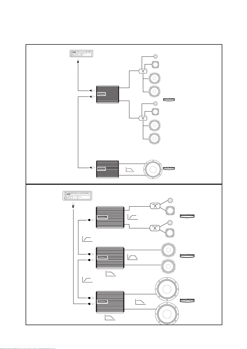
SYSTEM CHART / SYSTEM-DIAGRAMM / EXEMPLES DE SYSTEME /
RDS
TA
231
456
65Hz
50Hz-300Hz
65Hz
300Hz
65Hz
300Hz
50Hz
SYNTHESIS1000
SYNTHESIS1000
SYNTHESIS1000
DIAGRAMMA DI SISTEMA/ DIAGRAMA DEL SISTEMA
RDS
231
TA
456
SYNTHESIS1000
SYNTHESIS1000
III
Page 5

INTRODUCTION
The name of MACRON has always been the synonim of a European acoustic and musical
tradition in the pursue of the top sound quality. The fact that you chose to buy this product
means that you agree with us. With the help of this manual you will be able to maximize the
enjoyment you will get out of your new SYNTHESIS1000 amplifier’s outstanding features.
This amplifier incorporates many advanced fatures. Therefore, it is essential that all signal
sources, speakers and interconnections are of the highest sound quality. We strongly
recommend the use of MACROM head units, power amplifiers, speaker systems, high-quality
interconnection cables and accessories because the integration of these products is very
complex. We advise you to have it installed by your MACROM dealer.
This product has no user-adjustable controls; reand this manual carefully in order to become
well acquainted with all the special features and functions of your new SYNTHESIS1000
amplifier. Do not hesitate to contact your MACROM dealer should you have any problem.
PRECAUTIONS
1. The unit may be damaged by wrong lead connection, therefore read carefully the
instructions of this manual for the correct connection of the leads.
2. The last lead to be connected is the one to the positive (+) terminal of the battery; connect
this lead only after having completed and checked all other connections.
3. Be sure to install the crossover in a position with good air circulation and good heat
dissipation.
4. In case of fuse replacement make sure to replace it with a fuse of the same amperage. If
fuses blow more than once, carefully check all electrical connections. Also have your car’s
voltage regulator checked. Do not attempt to repair the unit yourself. If repairs are ever
needed, take the unit to your MACROM dealer or to your nearest MACROM service
station.
5. In order to get the best possible performance from this unit, make sure that the
temperature inside your car is within the range of -10° C and +60° C before you switch the
unit on. Good air circulation is essential to prevent heat build-up inside the unit.
FEATURES
• MIXED MONO OPERATION, 3/2/1 CHANNELS
• INPUT MODE SELECTOR: MONO - STEREO
• INTERNAL FILTER SELECTOR SWITCH: EITHER FLAT OR LOW- PASS OR HIGH-PASS
• CROSSOVER SLOPE SELECTOR FOR THE LOW-PASS FILTER
• EXTERNAL FILTER SELECTOR SWITCH: EITHER FLAT OR LOW-PASS OR HIGH-PASS
• SENSITIVITY RANGE SELECTOR
• CONTINUOUS HIGH-PASS FREQUENCYADJUSTMENT
• CONTINUOUS LOW-PASS FREQUENCY ADJUSTMENT
• CONTINUOUS SEPARATE LEFT AND RIGHT SENSITIVITY ADJUSTMENT
• MOS-FET POWER SUPPLY
• “CHECK CONTROL” STATUS INDICATOR
• REMOTE ON AND OFF
• GOLD-PLATED RCAINPUT CONNECTIONS
• PROFESSIONAL GOLD-PLATED SCREW-TYPE SUPPLY TERMINALS
1
Page 6

CONTROLS AND INDICATORS
RL
Bridged
1 • SPEAKER CONNECTORS: outputs for speakers connection.
The amplifier allows to connect speakers with minimum 0.5-ohm impedance per channel in
stereo configuration and with minimum 1-ohm impedance in mono-bridged configuration.
Should the 3-channel configuration be used, total impedance must not exceed the minimum 1ohm value.
Bridged
Bridged
RL
RL
3-channel configuration
2-channel configuration
1-channel configuration
Be sure to keep the right polarity in connecting the speakers. Avoid any contact between
poorly insulated wires and the car’s ground or metal pieces and between the wires
themselves.
2 • RCA INPUT CONNECTORS: connect the pre-output leads of the head unit to the input
connectors.
3 • RCA OUTPUT CONNECTORS: connect the pre-output leads to another amplifier.
5 • CHECK CONTROL LED: this led shows the amplifier’s status of operation:
WHITE: the unit is off. GREEN: the unit is working fine.
RED: the unit has entered the protection mode
SYNTHESIS1000 is equipped with three different protection devices:
- Overheating: in case of wrong installation and of amplifier’s overheating, the unit enters the
protection mode before being damaged. As soon as the temperature returns to normal values
and mistakes are corrected, the unit resumes normal operation.
- Overloads: in case a series of speakers is connected to the amplifier with the total
impedance value dropping below a tolerable level, i.e. 0.5 Ohm, the amplifier enters the
protection mode. To restore normal operation switch off the head unit and then switch it on
again.
- Output short circuit: in case of a short circuit at the speaker outlets the unit enters the
protection mode in order to avoid serious damage to the end-stage transistors. Normal
operation is resumed by removing the short circuit and by switching the head unit on again.
6 • FAN +/- CONNECTORS: allows to connect an external fan having a V=12Vcc supply
voltage and a power equal to P=6.6 W. approx.
7 • BATT + CONNECTOR for EXTERNAL CONDENSER: connect this terminal directly to the
positive pole of a (1 or 1.5) FARAD condenser of 24CARAT PE1.0 or PE1.5 so that the
amplifier’s dynamic capacities are increased. (it is advisable to position the condenser as
close as possibile to the SYNTHESIS1000 amplifier).
NOTABENE: charge the condenser by means of the resistance included in the
packaging before connecting it to the amplifier.
8 • BATT + LEAD: connect it directly to the battery positive pole (+) by using a cable with an
adequate section. Place a fuse between the battery and the amplifier so that the fuse is as
close as possible to the battery.
9 • GND CONNECTOR: Do not connect it directly to the battery negative pole (-) but connect
it to a clean part (i.e. paint-free) of the vehicle’s chassis by using a cable with an adequate
section.
2
Page 7

CONTROLS AND INDICATORS
10 • GND CONNECTOR for EXTERNAL CONDENSER: connect it directly to the negative
pole of a (1 or 1.5) FARAD condenser of 24CARAT PE1.0 or PE1.5 so that the amplifier’s
dynamic capacities are increased. (It is advisable to position the condenser as close as
possibile to the SYNTHESIS1000 amplifier).
NOTABENE: charge the condenser by means of the resistance included in the
packaging before connecting it to the amplifier.
11 • REMOTE IN/OUT CONNECTOR: IN should be connected to the remote switch-on output
lead or to the output lead of the power antenna coming from the head unit. By doing so the
SYNTHESIS1000 can be switched on and off through the head unit. Another amplifier can be
connected through OUT. If this is the case, one or more amplifiers can be switched on through
one connection to the head unit. (The OUT output is delayed compared to the remote ON
input).
12 • LOW PASS FREQUENCYADJUSTMENT: allows continuous Low-Pass filter adjustment
13 • LOW PASS FILTER CROSSOVER SLOPE SELECTOR: allows to select the Low-Pass
filter crossover slope in the 12dB/Oct-24dB/Oct range; when set at the 24dB position ONLY ,
both internal and external Low-Pass filter configuration switches automatically to the MONO
configuration.
14 • HIGH PASS FREQUENCYADJUSTMENT: allows continuous High-Pass filter
adjustment.
15 • EXTERNAL FILTER SELECTOR SWITCH (Flat-HI-LOW): allows to select the desired
type of filter either to connect externally a further amplifier or to disable the filter itself.
16 • INTERNAL FILTER SELECTOR (Flat-HI-LOW): allows to select the desired type of filter
either to connect externally a further amplifier or to disable the filter itself.
17 • LEFT INPUT GAIN ADJUSTMENT CONTROL: allows to adjust the input sensitivity of
the left channel only. It ranges from 0.2 mV to 8V.
If the amplifier is to be connected to a head unit that is fitted with preamplified RCA outputs,
proceed as follows:
a) set the volume control of your unit to 3/4 of maximum output level;
b) set the input gain control to the point where the maximum sound level with no distortion is
obtained.
18 • RIGHT INPUT GAIN ADJUSTMENT CONTROL: allows to adjust the input sensitivity of
the right channel only. It ranges from 0.2 mV to 8V.
If the amplifier is to be connected to a head unit that is fitted with preamplified RCA outputs,
proceed as follows:
a) set the volume control of your unit to 3/4 of maximum output level;
b) set the input gain control to the point where the maximum sound level with no distortion is
obtained.
19 • SENSITIVITY RANGE SELECTOR: allows to select the sensitivity range that is most
suitable to the unit installed.
20 • INPUT MODE SELECTOR: allows to select the amplifier’s configuration as follows:
a) STEREO “ST” when the amplifier is used as a two-channel stereo system (right + left);
b) MONO (L mono) when the amplifier is driven by one input signal “Left” and outputs are
mono-bridged.
3
Page 8

TECHNICAL DATA
Model SYNTHESIS1000
IHF 202 1500 Watt
RMS @ 1 kHz < 0.08% THD at 4 ohms 125 Watt x 2
RMS @ 1 kHz < 0.2% THD at 2 ohms 250 Watt x 2
RMS @ 1 kHz < 0.5% THD at 1 ohms 500 Watt x 2
RMS @ 1 kHz < 0.2% THD mono at 4 ohms 500 Watt x 1
RMS @ 1 kHz < 0.5% THD mono at 2 ohms 1000 Watt x 1
Low-Pass 30-600 Hz
Low Pass crossover slope 12-24 dB/Octave
High-Pass 30-600 Hz
High Pass crossover slope 12 dB/Octave
Frequency response ± 1 dB 10 - 50,000 Hz
Total harmonic distortion 0.08%
IHFA-weighted S/N (signal-to-noise ratio) >100 dB
Input sensitivity/impedance 200-8000 mV/22 kohms
Speaker impedance
stereo 0.5 ohms min
mono 1 ohms min
Power supply 14.4 V DC (11-16 V allowed)
Weight 4.5 kg
Size 259(l) x 67(h) x 320(d) mm
Due to continuing improvement, the features and the design are subject to change without
notice.
4
Page 9

EINFÜHRUNG
MACROM ist seit jeher in der europäischen Akustik- und Musiktradition an der Spitze und
nach der Erreichung der besten Tonqualität bestrebt. Mit der Wahl dieses Erzeugnisses haben
Sie gezeigt, daß Sie der gleichen Auffassung sind wie wir. Diese Anleitung wird Sie in die Lage
versetzen, alle hochmodernen Eigenschaften dieses neuen Verstärkers SYNTHESIS1000 zu
schätzen.
Dieser Verstärker vereint eine Reihe bemerkenswerter technischer Merkmale, die die höchste
Qualität aller Signalquellen, Lautsprecher und Anschlußgeräte voraussetzen. Wir empfehlen
den Einsatz von hochqualitativen Haupteinheiten, elektronischen Crossovers,
Lautsprechersystemen, Anschlußkabeln und Zubehör der Marke MACROM. Da die Integration
dieser Erzeugnisse äußerst komplex ist, empfehlen wir Ihnen, diesen SYNTHESIS1000 von
Ihrem offiziellen MACROM-Händler installieren zu lassen.
Dieser Verstärker hat keine vom Benutzer regelbaren Bedienungs- und Steuervorrichtungen.
Lesen Sie die Anleitung eingehend, um sich mit den besonderen Eigenschaften und
Funktionen Ihres neuen SYNTHESIS1000 MACROM vertraut zu machen. Im Zweifelsfall
wenden Sie sich bitte an Ihren MACROM-Händler.
VORSICHTSMAßNAHMEN
1. Jegliche falsche Verbindung könnte das Gerät beschädigen. Lesen Sie aufmerksam die
Anleitungen für den Kabelanschluß durch.
2. Das Batteriekabel zuletzt an den Pluspol (+) der Batterie anschließen und nur, nachdem
alle anderen Anschlüsse ausgeführt worden sind.
3. Man vergewissere sich, daß die elektronische Frequenzweiche an einer Stelle installiert
wird, wo gute Luftzirkulation und eine gute Wärmeabgabe gewährleistet sind.
4. Die Sicherungen müssen immer durch Sicherungen mit der gleichen Amperezahl ersetzt
werden, um schwere Beschädigungen der Gerätekomponenten zu vermeiden. Man lasse
bei mehrmaligem Durchbrennen der Sicherungen die Lichtmaschine des Wagens
überprüfen. Das Gerät niemals selber reparieren, sondern jegliche Reparatur Ihrem
MACROM-Vertragshändler oder der nächsten MACROM-Dienststelle übergeben.
5. Um die besten Leistungen zu erzielen sollte die Temperatur im Wageninnenraum zwischen
-10° C und +60° C liegen, bevor man das Gerät einschaltet.
EIne gute Lüftung des Wageninnenraums ist erforderlich, um die Überhitzung der inneren
Stromkreise des Gerätes zu vermeiden.
EIGENSCHAFTEN
• MIXED-MONO-BETRIEB, 3/2/1 KANÄLE
• MONO-, STEREO-EINGANGSMODUSWAHLSCHALTER
• WAHLSCHALTER FÜR DEN FLAT-, HIGH-PASS- UND LOW-PASS-INNENFILTER
• WAHLSCHALTER FÜR DIE TRENNSTEILHEIT FÜR DEN LOW-PASS-FILTER
• WAHLSCHALTER FÜR DEN FLAT-, HIGH-PASS- UND LOW-PASS-AUßENFILTER
• WAHLSCHALTER FÜR DEN EMPFINDLICHKEITSBEREICH
• STUFENLOSE HIGH-PASS-FREQUENZ-REGELUNG
• STUFENLOSE LOW-PASS-FREQUENZ-REGELUNG
• STUFENLOSE, GETRENNTE REGELUNG DER EMPFINDLICHKEIT LINKS UND RECHTS
• MOS-FET-SPEISUNG
• “CHECK CONTROL”-STATUSANZEIGE
• REMOTE-EIN- UND -AUSSCHALTUNG
• VERGOLDETE RCA-EINGANGSANSCHLÜSSE
• VERGOLDETE, PROFESSIONELLE SCHRAUBANSCHLÜSSE
5
Page 10

EINSTELLUNGEN UND ANZEIGEN
RL
Bridged
1 und 4. VERBINDER FÜR LAUTSPRECHER: Ausgänge für den Anschluß der Lautsprecher.
An den Verstärker können Lautstärker mit einer Mindestimpedanz von 0,5 Ohm pro Kanal in
der Stereokonfiguration angeschlossen werden, während bei überbrücktem Mono-Anschluß
eine Impedanz von 1 Ohm vorgesehen ist. Falls eine Konfiguration mit 3 Kanälen gewählt
wird, darf die Gesamtimpedanz den Mindestwert von 1 Ohm nicht überschreiten.
Bridged
Bridged
RL
3-Kanal-Ausführung 2-Kanal-Ausführung 1-Kanal-Ausführung
Beim Anschluß der Lautsprecher ist auf die korrekte Polschaltung zu achten. Massekontakte
bzw. Kontakte mit Metallteilen des Autos von nicht entsprechend isolierten Kabeln bzw.
Kontakte zwischen diesen Kabeln sind zu vermeiden.
2 • RCA-EINGANGSANSCHLÜSSE: Die Ausgangskabel ´Pre´ Ihres Hauptgerätes an die
Eingangsverbinder anschließen
3 • RCA-AUSGANGSANSCHLÜSSE: Die Ausgangskabel ´Preout an einen anderen
Verstärker anschließen.
5 • CHECK CONTROL ANZEIGE: Dieses LED zeit den Betriebsstatus des Verstärkers an.
WEISS: Das Gerät ist ausgeschalten. GRÜN: Das Gerät funktioniert einwandfrei
ROT: Das Gerät steht unter Schutz. Der SYNTHESIS1000 verfügt über drei Schutzvorrichtungen:
- Überhitzungsschutz: Bei Installationsfehlern bzw. bei Überhitzung des Verstärkers wirkt der
Schutz vor Beschädigung des Gerätes ein. Sobald die Temperatur wieder auf normale Werte
absinkt, wird das Gerät wieder eingeschalten.
- Überlastungsschutz: Falls mehrere Lautsprecher an den Verstärker angeschlossen werden
und die Gesamtimpedanz unter die zulässigen Grenzwerte "0,5 Ohm" sinkt, wird der
Verstärker durch Selbstschutz außer Betrieb gesetzt. Zum Wiedereinschalten muß das
Hauptgerät aus- und wieder eingeschalten werden.
- Kurzschluß am Ausgang: Bei Kurzschluß an den Lautsprecherausgängen wird die
Schutzfunktion zwecks Vermeidung hoher Endtransistorschäden ausgelöst. Durch Beseitigung
des Kurzschlusses und Wiedereinschalten des Hauptgeräts wird der Normalbetrieb wieder
hergestellt.
RL
6 • VERBINDER +/- LAUFRAD:
Damit kann ein externes Laufrad mit einer Speisungsspannung von V=12Vco Gleichstrom und
einer Leistung von etwa P=6,6W angeschlossen werden
7 • VERBINDER + BATT FÜR DEN EXTERNEN KONDENSATOR: Diese Klemme direkt an
den Pluspol eines Kondensators zu (1 bzw. 1,5) FARAD der 24CARAT PE1,0 oer PE1,5
anschließen, um die dynamischen Kapazitätswerte des Verstärkers zu erhöhen (Der
Kondensator sollte möglichst nahe am Verstärker SYNTHESIS1000 installiert werden)
Achtung, lassen Sie den Kondensator über den Widerstand aufladen, der in dessen
Verpackung enthalten ist, ehe Sie ihn an den Verstärker anschließen.
8 • VERBINDER + BATT: Diese Klemme mit einem entsprechend bemessenen Kabel direkt
an den Pluspol der Batterie anschließen und dabei möglichst nahe an der Batterie eine
Sicherung zwischen die Batterie und den Verstärker zwischenschalten.
9 • GND-VERBINDER: Diese Klemme NICHT direkt an den MINUSPOL der Batterie, sondern
mit einem Kabel mit geeignetem Querschnitt an eine blanke Stelle (d.h. ohne Lack) des
Autorahmens anschließen.
6
Page 11

EINSTELLUNGEN UND ANZEIGEN
10 • GND-VERBINDER FÜR EXTERNEN KONDENSATOR: Diese Klemme direkt an den
Minuspol eines Kondensators zu (1 bzw. 1,5) FARAD der 24CARAT PE1,0 oer PE1,5
anschließen, um die dynamischen Kapazitätswerte des Verstärkers zu erhöhen
(Der Kondensator sollte möglichst nahe am Verstärker SYNTHESIS1000 installiert werden)
Achtung: Lassen Sie den Kondensator über den Widerstand aufladen, der in dessen
Verpackung enthalten ist, ehe Sie ihn an den Verstärker anschließen.
11 • REMOTE-IN/OUT-VERBINDER: Der IN-Kontakt muß an den Ausgangsleiter der Remote-
on-Einschaltung (Ferneinschaltung) oder der automatischen Antenne angeschlossen werden,
die von der Haupteinheit kommen. Damit kann der SYNTHESIS1000 über die Haupteinheit
ein- und ausgeschalten werden. Über den OUT-Kontakt kann ein anderer Verstärker
angeschlossen werden. In diesem Fall können über die Haupteinheit mit einem einzigen
Anschluß, der von dieser Einheit kommt (der Ausgang OUT ist im Verhältnis zum RemoteEingang ON verzögert) ein oder mehrere Verstärker eingeschalten werden.
12 • LOW-PASS-FREQUENZREGELUNG: Damit kann der Low-Pass-Filter stufenlos geregelt
werden.
13 • WAHLSCHALTER FÜR TRENNSTEILHEIT für den LOW-PASS-FILTER: Damit kann die
Trennsteilheit des Low-Pass-Filters von 12dB/Oct auf 24dB/Oct gewählt werden. NUR bei
Einstellung auf 24dB wird die Konfiguration des internen und externen Low-Pass-Filters
automatisch auf MONO umgestellt.
14 • HIGH-PASS-FREQUENZREGELUNG: Damit kann der High-Pass-Filter stufenlos
geregelt werden.
15 • WAHLSCHALTER DES EXTERNEN FILTERS (Flat - High - Low). Damit kann der
gewünschte Filtertyp für den eventuellen Außenanschluß eines anderen Verstärkers
eingestellt bzw. der Filter ausgeschlossen werden.
16 • WAHLSCHALTER DES INTERNEN FILTERS (Flat - High - Low). Damit kann der
gewünschte Filtertyp für den Verstärker eingestellt bzw. der Filter ausgeschlossen werden.
17 • LINKE EINGANGSGEWINNREGELUNG
Damit kann die Eingangsempfindlichkeit des linken Kanals geregelt werden; die Regelung
erfolgt zwischen 0,2mV und 8V. Falls Sie ein Gerät anschließen, das mit vorverstärkten RCAAusgängen ausgestattet ist, muß wie folgt vorgegangen werden:
a) Den Lautstärkeregler Ihres Geräts auf 3/4 des Höchstausgangs stellen.
b) Die Eingangsgewinnregelung des Verstärkers so einstellen, daß der maximale
Lautstärkepegel ohne Verzerrung erzeugt wird.
18 • RECHTE EINGANGSGEWINNREGELUNG
Damit kann die Eingangsempfindlichkeit des rechten Kanals geregelt werden; die Regelung
erfolgt zwischen 0,2mV und 8V.
Falls Sie ein Gerät anschließen, das mit vorverstärkten RCA-Ausgängen ausgestattet ist,
muß wie folgt vorgegangen werden:
a) Den Lautstärkeregler Ihres Geräts auf 3/4 des Höchstausgangs stellen.
b) Die Eingangsgewinnregelung des Verstärkers so einstellen, daß der maximale
Lautstärkepegel ohne Verzerrung erzeugt wird.
19 • WAHLSCHALTER FÜR DEN EMPFINDLICHKEITSBEREICH: Damit kann der
geeignetste Empfindlichkeitsbereich in Abhängigkeit von der installierten Einheit gewählt
werden.
20 • WAHLSCHALTER FÜR DEN EINGANGSMODUS
Dient zur Einstellung der Verstärkerkonfiguration wie folgt:
a) STEREO “ST”, falls er als Verstärker mit zwei Stereokanälen “links und rechts” verwen
det wird.
b) MONO “L mono”, wenn er von nur einem Eingangssignal “Left” gesteuert wird und die
7
Page 12

TECHNISCHE DATEN
Modell SYNTHESIS1000
IHF 202 1500 W
RMS@ 1kHz < 0,08 % THD bei 4 ohm 125 W x 2
RMS@ 1kHz < 0,2 % THD bei 2 ohm 250 W x 2
RMS@ 1kHz < 0,5 % THD bei 1 ohm 500 W x 2
RMS@ 1kHz < 0,2 % THD Mono bei 4 ohm 500 W x 1
RMS@ 1kHz < 0,5 % THD Mono bei 2 ohm 1000 W x 1
Low-Pass (30-600)Hz
Low-Pass-Crossover-Steilheit 12 dB/Oktave-24 dB/Oktave
High-Pass (30-600) Hz
High-Pass-Crossover-Steilheit 12 dB/Oktave
Frequenzgang +/- 1 dB (10-50.000) Hz
Nichtlineare Verzerrung 0,08%
Geräuschabstand, IHFA-bewertet >100 dB
Eingangsempfindlichkeit/Impedanz 200-8.000mV/22 kohm
Lautsprecherimpedanz
Stereo Min. 0,5 ohm
Mono Min. 1 ohm
Stromversorgung 14,4 V DC (11-16V zulässig)
Gewicht 4.5 kg
Abmessungen 259(L) x 87(H) x 320(T) mm
Änderungen der technischen Daten und des Designs können zwecks ständiger
Produktverbesserung jederzeit unangekündigt vorgenommen werden.
8
Page 13

INTRODUCTION
Depuis toujours le nom MACRON est synonyme d’une tradition acoustique et musicale
européenne projetée vers la réalisation de la meilleure qualité sonore. Le fait que vous avez
choisi ce produit signifie que vous êtes d’accord avec nous. Grâce à ce manuel vous pourrez
apprécier toutes les caractéristiques avancées de ce nouvel amplificateur SYNTHESIS1000.
Cet amplificateur renferme toute une serie de caractéristiques techniques remarquables et il
est donc très important que toutes les sources de signal, les haut-parleurs et les appareils
d’interconnexion soient d’une qualité excellente. Nous recommandons l’utilisation d’unités
principales, d’amplificateurs de puissance, de systémes de haut-parleurs, de câbles de
connexion et d’accessoires de haute qualité de MACROM puisque l’intégration de ces
produits est de nature assez complexe. Nous vous conseillons de faire installer cet
amplificateur par votre revendeur autorisé MACROM. Ce produit n’a pas de commandes ou
de contrôles réglables par l’utilisateur; lisez attentivement ce manuel pour vous familiariser
avec les caractéristiques spéciales et les fonctions de vostre nouvel amplificateur
SYNTHESIS1000. En cas de doute addressez-vous a votre revendeur autorisé MACROM.
PRECAUTIONS
1. Toute mauvaise connexion pourrait endommager l’unité. Lire attentivement les instructions
pour la connexion des fils données dans ce manuel.
2. Il faut connecter le fil de la batterie au terminal (+) de la batterie même en dernier et
seulement après avoir effectué et contrôlé toutes les autres connexions.
3. Il faut s’assurer que le séparateur soit installé dans une position avec une bonne circulation
d’air et une bonne dissipation de la chaleur.
4. Les fusibles doivent toujours être remplacé avec des fusibles du même ampérage pour
éviter de graves dommages aux composants de l’appareil. Si les fusibles devaient sauter
plusieurs fois de suite, faire contrôler le régulateur de voltage de votre voiture. N’essayez
jamais de réparer l’appareil vous-même, mais confiez-la au distributeur MACROM ou au
centre d’assistance MACROM de votre zone.
5. Pour obtenir les meilleures performances de votre appareil faites en sorte que la
température à l’intérieur de la voiture soit comprise entre -10° C et +60° C avant d’allumer
l’appareil. Une bonne ventilation est indispensable pour éviter la surchauffe des circuits
internes.
CARACTERISTIQUES
• FONCTIONNEMENT MIXED MONO, 3/2/1 CANAUX
• SÉLECTEUR DU MODE D’ENTRÉE, MONO - STÉRÉO
• SÉLECTEUR DU FILTRE INTÉRIEUR: FLAT OU LOW-PASS OU HIGH-PASS
• SÉLECTEUR DE LA PENTE DE CROISEMENT POUR LE FILTRE LOW-PASS
• SÉLECTEUR DU FILTRE EXTÉRIEUR: FLAT OU LOW-PASS OU HIGH-PASS
• SÉLECTEUR DE LA GAMME DE SENSIBILITÉ
• RÉGLAGE CONTINU DE LA FRÉQUENCE HIGH-PASS
• RÉGLAGE CONTINU DE LA FRÉQUENCE LOW-PASS
• RÉGLAGE CONTINU DE LA SENSIBILITÉ DROIT ET GAUCHE DE FAÇON SÉPARÉE
• ALIMENTATEUR MOS-FET
• INDICATEUR D’ÉTAT “CHECK CONTROL”
• ALLUMAGE ET EXTINCTION À DISTANCE
• TERMINAUX D’ENTRÉE RCA DORÉS
• TERMINAUX D’ALIMENTATION PROFESSIONELS À VIS, DORÉS
9
Page 14

CONTROLES ET INDICATEURS
RL
Bridged
1 • CONNECTEURS SPEAKER: sorties pour la connexion des haut-parleurs.
L’amplificateur permet la connexion de haut-parleurs ayant une impédance minimum de 0,5
ohm par canal dans la configuration stéréo et une impédance minimum de 1 ohm quand la
connexion est pontée en monophonie. Si l’on utilise la configuration à 3 canaux, l’impédance
totale ne doit pas être supérieure à une valeur minimum de 1 ohm.
Bridged
Bridged
RL
Config. à 3 canaux Config. à 2 canaux Config. à 1 canal
Assurez-vous d’observer la bonne polarité pendant la connexion des haut-parleurs. Evitez que
les fils non isolés puissent entrer en contact avec la masse, avec les parties métalliques de la
voiture ou ne fassent contact entre eux.
2 • CONNECTEURS D’ENTREE RCA: reliez les fils de sortie Pre de l’unité principale aux
connecteurs d’entrée.
3 • CONNECTEURS DE SORTIE RCA: reliez les fils de sortie Pre-out à un autre
amplificateur.
5 • LED CHECK CONTROL: cette LED indique l’état de fonctionnement de l’amplificateur.
BLANC: l’unité est éteinte. VERT: l’unité fonctionne très bien.
ROUGE: l’unité est entrée en état de protection.
LE SYNTHESIS1000 est équipé de trois protections différentes:
- Surchauffe: en cas d’erreurs d’installation, l’unité entre en état de protection avant de subir
des dommages. Dès que la température retourne à des valeurs normales et les erreurs sont
corrigées, l’unité reprend son fonctionnement normal;
- Surcharge: si plusieurs haut-parleurs sont connectés à l’amplificateur et l’impédance totale
est inférieure au seuil permis (0,5 ohm), l’amplificateur entre automatiquement en état de
protection. Pour que l’unité reprenne son fonctionnement normal, il faut éteindre et allumer de
nouveau l’unité principale;
- Court circuit à la sortie: en cas de court circuit à la sortie des haut-parleurs, l’unité entre en
état de protection pour prévenir de sérieux dommages aux transistors finaux. Pour qu’elle
revienne à l’état de fonctionnement normal, il faut éliminer le court circuit et allumer de
nouveaux l’unité principale.
6 • CONNECTEURS +/- VENTILATEUR: pour relier un ventilateur extérieur ayant une
tension de marche de V=12Vcc et une puissance de P=6,6W.
7 • CONNECTEUR + BATT pour CONDENSATEUR EXTERIEUR: il faut le relier directement
au pôle positif de un condensateur de (1 ou 1,5) FARAD de 24CARAT PE1.0 ou P.E1.5 de
sorte à augmenter les capacités dynamiques de l’amplificateur (il vaux mieux positionner le
condensateur de façon qu’il soit près de l’amplificateur SYNTHESIS1000 autant que
possible).
Attention: il faut charger le condensateur au moyen de la résistance incluse dans son
emballage avant de le relier à l’amplificateur.
8 • CONNECTEUR + BATT: il doit être relié directement au pôle positif (+) de la batterie en
utilisant un fil ayant une section adéquate et en interposant un fusible entre l’amplificateur et la
batterie de façon qu’il soit prés de celle-ci autant que possible.
9 • CONNECTEUR GND (Masse): il NE faut PAS le relier directement au pôle NEGATIF (-)
de la batterie ma il doit être relié, en utilisant un fil ayant une section adéquate, à un point
propre (c’est-à-dire sans peinture) du châssis de la voiture.
RL
10
Page 15

CONTROLES ET INDICATEURS
10 • CONNECTEUR + BATT pour CONDENSATEUR EXTERIEUR: il faut le relier
directement au pôle positif de un condensateur de (1 ou 1,5) FARAD de 24CARAT PE1.0 ou
P.E1.5 de sorte à augmenter les capacités dynamiques de l’amplificateur (il vaux mieux
positionner le condensateur de façon qu’il soit près de l’amplificateur SYNTHESIS1000 autant
que possible).
Attention: il faut charger le condensateur au moyen de la résistance incluse dans son
emballage avant de le relier à l’amplificateur.
11 • CONNECTEUR REMOTE IN/OUT: IN doit être relié au fil de sortie de l’allumage remote-
on (allumage à distance) ou de l’antenne automatique qui sort de l’unité principale. Ceci
permet d’allumer et d’éteindre le SYNTHESIS1000 en allumant et éteignant l’unité principale.
On peut relier un autre amplificateur par OUT: dans ce cas, on peut allumer un ou plusieurs
amplificateurs au moyen d’une seule connexion à l’unité principale (La sortie OUT est retardée
par rapport à l’entrée remote ON)
12 • REGLAGE DE LA FREQUENCE LOW-PASS: permet le réglage continu du filtre Low-
Pass.
13 • SELECTEUR DE LA PENTE DE CROISEMENT pour le FILTRE LOW-PASS: permet le
réglage de la pente de croisement du filtre Low-Pass entre 12 et 24 dB/Oct. Dans la position
de 24 dB SEULEMENT, la configuration du filtre Low-Pass, tant intérieur qu’extérieur, se
transforme automatiquement en configuration MONO.
14 • REGLAGE DE LA FREQUENCE HIGH-PASS: permet le réglage continu du filtre High-
Pass.
15 • SELECTEUR DU FILTRE EXTERIEUR (Flat - HI - LOW): permet de selectionner le type
de filtre que l’on désire pour connecter un autre amplificateur ou bien de désactiver le filtre.
16 • SELECTEUR DU FILTRE INTERIEUR (Flat - HI - LOW): permet de selectionner le type
de filtre que l’on désire pour connecter un autre amplificateur ou bien de désactiver le filtre.
17 • REGLAGE DU GAIN A L’ENTREE GAUCHE: permet le réglage de la sensibilité d’entrée
exclusivement du canal gauche. Les valeurs varient entre 0,2 mV et 8V.
Si vous désirez relier une unité qui possède des sorties préamplifiées du type RCA, procédez
de la manière suivante:
a) réglez le volume de l’unité principale à 3/4 du niveau maximum de sortie;
b) réglez le contrôle du gain à l’entrée de l’amplificateur de façon à obtenir la pression
sonore maximum sans distorsion.
18 • REGLAGE DU GAIN A L’ENTREE DROIT: permet le réglage de la sensibilité d’entrée
exclusivement du canal droit. Les valeurs varient entre 0,2 mV et 8V.
Si vous désirez relier une unité qui possède des sorties préamplifiées du type RCA, procédez
de la manière suivante:
a) réglez le volume de l’unité principale à 3/4 du niveau maximum de sortie;
b) réglez le contrôle du gain à l’entrée de l’amplificateur de façon à obtenir la pression
sonore maximum sans distorsion.
19 • SELECTEUR DE LA GAMME DE SENSIBILITE: permet de selectionner la gamme de
sensibilité la plus adaptée à l’unité installée.
20 • SELECTEUR DU MODE D’ENTREE: permet de sélectionner la configuration de
l’amplificateur, comme suit:
a) STEREO “ST”:lorsque l’amplificateur est utilisé comme un systéme stéréo à deux
canaux “gauche + droit”;
b) MONO “Lmono”:lorsque un seul signal “Left” pilote l’amplificateur et les sorties sont
pontées en monophonie.
11
Page 16

DONNEES TECHNIQUES
Modèle SYNTHESIS1000
IHF 202 1500 Watt
RMS @ 1 kHz < 0,08% THD à 4 ohm 125 Watt x 2
RMS @ 1 kHz < 0,2% THD à 2 ohm 250 Watt x 2
RMS @ 1 kHz < 0,5% THD à 1 ohm 500 Watt x 2
RMS @ 1 kHz < 0,2% THD mono à 4 ohm 500 Watt x 1
RMS @ 1 kHz < 0,5% THD mono à 2 ohm 1000 Watt x 1
Low-Pass 30-600 Hz
Pente de croisement Low-Pass 12-24 dB/Octave
High-Pass 30-600 Hz
Pente de croisement High-Pass 12 dB/Octave
Réponse en fréquence ± dB 10-50.000 Hz
Distorsion harmonique totale 0,08%
Rapport signal/bruit, pesé IHFA >100 dB
Sensibilité d’entrée/impédance 200-8000 mV/22 kohm
Impédance des haut-parleurs
stéréo 0.5 ohm min
mono 1 ohm min
Alimentation 14,4 V DC (11-16V admis)
Poids 4.5 kg
Dimensions 259(l) x 67(h) x 320(p) mm
A cause d’améliorations continues apportées au produit, les caractéristiques et le dessin sont
sujets à des modifications sans préavis.
12
Page 17

INTRODUZIONE
MACROM è da sempre sinonimo di tradizione acustica e musicale europea, tesa al
raggiungimento della migliore qualità sonora. Il fatto che Voi abbiate scelto questo prodotto
significa che anche Voi la pensate come noi. Grazie a questo manuale sarete in grado di
apprezzare tutte le avanzate caratteristiche di questo nuovo Amplificatore SYNTHESIS1000
Questo Amplificatore racchiude una serie ragguardevole di caratteristiche tecniche, per cui è
fondamentale che tutte le sorgenti di segnale, gli altoparlanti e le apparecchiature
d’interconnessione siano della massima qualità. Raccomandiamo l’uso di unità principali,
crossover elettronici, sistemi d’altoparlanti, cavi di collegamento ed accessori di alta qualità
della MACROM; poiché l’integrazione di questi prodotti è di natura estremamente complessa
vi consigliamo di fare installare questo SYNTHESIS1000 dal Vostro rivenditore autorizzato
MACROM.
Questo Amplificatore non ha comandi o controlli regolabili dall’utilizzatore, leggete
attentamente questo manuale, per familiarizzarVi con le caratteristiche speciali e le funzioni
del Vostro nuovo SYNTHESIS1000 MACROM. In caso di dubbi, rivolgeteVi al Vostro
rivenditore autorizzato MACROM.
PRECAUZIONI
1. Ogni collegamento scorretto potrebbe danneggiare l’unità. Leggere attentamente le
istruzioni per il collegamento dei fili riportate da questo manuale.
2. Collegare per ultimo il filo della batteria al terminale (+) della stessa e solo dopo aver
completato e controllato tutti gli altri collegamenti.
3. Assicurarsi di installare l`amplificatore in una posizione nella quale sia garantita una buona
circolazione dell’aria e una buona dissipazione del calore.
4. I fusibili devono essere sempre sostituiti con fusibili di identico amperaggio onde evitare
gravi danni ai componenti. Fare controllare inoltre il regolatore di voltaggio dell’auto.
Evitare di riparare l’unità da sé. Affidare l’eventuale riparazione al distributore MACROM o
al centro di assistenza MACROM di zona.
5. Per assicurarsi le migliori prestazioni dall’unità fare in modo che la temperatura all’interno
dell’automobile sia compresa fra i -10°C ed +60°C prima di accendere l’unità stessa.
CARATTERISTICHE
• FUNZIONAMENTO MIXED MONO, 3/2/1 CANALI
• SELETTORE DEL MODO DI INGRESSO, MONO - STEREO
• SELETTORE DEL FILTRO (FLAT - PASSAALTO - PASSA BASSO) INTERNO
• SELETTORE DELLA PENDENZADI TAGLIO PER ILFILTRO PASSA BASSO
• SELETTORE DEL FILTRO (FLAT - PASSAALTO - PASSA BASSO) ESTERNO
• SELETTORE DELLA GAMMA DI SENSIBILITÀ
• REGOLAZIONE IN CONTINUO DELLA FREQUENZA PASSA ALTO
• REGOLAZIONE IN CONTINUO DELLA FREQUENZA PASSA BASSO
• REGOLAZIONE IN CONTINUO DELLA SENSIBILITA SINISTRO E DESTRO SEPARATE
• ALIMENTAZIONE A MOS-FET
• INDICATORE DI STATO “CHECK CONTROL”
• ACCENSIONE E SPEGNIMENTO A DISTANZA
• TERMINALI DI INGRESSO RCA DORATI
• TERMINALI DI CONNESSIONE PROFESSIONALE A VITE DORATI
13
Page 18

CONTROLLI & INDICATORI
RL
Bridged
1e 4 CONNETTORI ALTOPARLANTI: Uscite per il collegamento degli altoparlanti.
L’amplificatore permette il collegamento di altoparlanti di impedenza minima di 0,5 ohm per
canale in configurazione stereo, mentre per il collegamento in mono “Bridged” un’ impedenza
di 1 ohm.Qualora si utilizzasse la configurazione 3 canali l’impedenza totale non deve
superare il valore minimo di 1 ohm.
Bridged
Bridged
RL
RL
Configurazione 3 canali
Configurazione 2 canali
Configurazione 1 canale
Assicurarsi di osservare la corretta polarità nel collegamento degli altoparlanti.
Non lasciate che cavi non adeguatamente isolati vengano in contatto con la massa, parti
metalliche dell`auto o facciano contatto fra di loro.
2 • CONNETTORI D’INGRESSO RCA: Collegare i cavi di uscita Pre della vostra unità princi
pale ai connettori di ingresso.
3 • CONNETTORI D’USCITA RCA: Collegare i cavi di uscita Preout ad un altro amplificatore.
5 • INDICATORE CHECK CONTROL: Questo led indica lo stato di funzionamento
dell`amplificatore. BIANCO: l`unità è spenta. VERDE: l`unità funziona perfettamente.
ROSSO: l`unità è in protezione.
Il SYNTHESIS1000 è provvisto di tre protezioni:
- Surriscaldamento, nel caso in cui vi siano errori d`installazione e l’amplificatore si
surriscalda,l’unità entra in protezione prima di danneggiarsi. Appena la temperatura tornerà
normale e gli errori tolti, l`unità riprenderà automaticamente il normale funzionamento.
- Sovraccarichi, nel caso in cui più altoparlanti vengano collegati all`amplificatore e
l`impedenza totale scenda sotto i limiti sopportabili “0,5 ohm”, l`amplificatore va in protezione.
Per ripristinare il funzionamento è necessario spegnere e riaccendere l`unità principale.
- Corto circuito in uscita, in caso di cortocircuito sulle uscite altoparlanti l`unità entra in
protezione per prevenire seri danni ai transistor finali. Il ritorno allo stato di normale
funzionamento si ottiene rimuovendo il cortocircuito e riaccendendo l`unità principale.
6 • CONNETTORI +/- VENTOLA: permette il collegamento di una ventola esterna che abbia
una tensione di alimentazione di V=12Vcc in continua e una potenza di circa P=6,6W.
7 • CONNETTORE + BATT per CONDENSATORE ESTERNO: Collegare questo morsetto
direttamente al positivo di un condensatore da (1 o 1,5) FARAD della 24CARAT PE1.0 o
PE1.5 in modo tale da aumentare le capacità dinamiche dell’amplificatore (il condensatore é
preferibile collocarlo il più vicino possibile all’amplificatore SYNTHESIS 1000).
Attenzione fate caricare il condensatore, tramite la resistenza che troverete nella
confezione dello stesso, prima di collegarlo all’amplificatore.
8 • CONNETTORE + BATT: Collegare questo morsetto direttamente al positivo della batteria
tramite un cavo di appropriate dimensioni e ponendo fra la batteria e l’amplificatore un fusibile
posto il più vicino possibile alla batteria.
9 • CONNETTORE GND: NON Collegare questo morsetto direttamente al NEGATIVO della
batteria ma collegarlo, con un cavo di appropriata sezione, ad un punto pulito (cioè privo di
vernice) del telaio dell’automobile.
14
Page 19

CONTROLLI & INDICATORI
10 • CONNETTORE GND per CONDENSATORE ESTERNO: Collegare questo morsetto
direttamente al negativo di un condensatore da (1 o 1,5) FARAD della 24CARAT PE1.0 o
PE1.5 in modo tale da aumentare le capacità dinamiche dell’amplificatore (il condensatore é
preferibile collocarlo il più vicino possibile all’amplificatore SYNTHESIS1000).
Attenzione fate caricare il condensatore, tramite la resistenza che troverete nella
confezione del condensatore, prima di collegarlo all’amplificatore.
11 • CONNETTORE REMOTE IN / OUT: il contatto IN va collegato al filo di uscita
d’accensione remote-on (accensione a distanza) o dell’antenna automatica provenienti
dall’unità principale. Questo permette di accendere e spegnere il SYNTHESIS 1000 tramite
l’unità principale; é possibile collegare un altro amplificatore tramite il contatto OUT, in questo
caso, tramite l’unità principale è possibile accendere uno o più amplificatori con un’unica
connessione proveniente dall’unità stessa (L’uscita OUT é ritardata rispetto all’ingresso
remote ON ).
12 • REGOLAZIONE DELLA FREQUENZA PASSA BASSO: permette la regolazione in
continuo del filtro passa basso.
13 • SELETTORE DELLA PENDENZADI TAGLIO per il FILTRO PASSA BASSO: permette
di selezionare la pendenza di taglio, del filtro passa basso, da 12dB/ Oct. a 24dB/Oct.; SOLO
nella posizione di 24dB la configurazione del filtro passa basso sia interno che esterno si
commuta automaticamente in configurazione MONO.
14 • REGOLAZIONE DELLA FREQUENZA PASSAALTO: permette la regolazione in
continuo del filtro passa alto.
15 • SELETTORE DEL FILTRO ESTERNO (Flat - HI - LOW): permette la selezione del tipo di
filtro desiderato per un’eventuale connessione esterna di un altro amplificatore, oppure
l’esclusione del filtro stesso.
16 • SELETTORE DEL FILTRO INTERNO (Flat - HI - LOW): permette la selezione del tipo di
filtro desiderato per l’amplificatore, oppure l’esclusione dello stesso filtro.
17 • REGOLAZIONE DEL GUADAGNO DI INGRESSO SINISTRO: permette la regolazione
della sensibilità d’ingresso solo del canale sinistro e varia da 0,2mV fino a 8V.
Quando dovete collegare un’unità che possiede uscite preamplificate del tipo RCA, procedere
nel seguente modo:
a) Collocare il controllo di volume della vostra unità a 3/4 dell`uscita massima
b) Girate il controllo di guadagno di ingresso dell`amplificatore in modo da ottenere la
massima pressione sonora ma senza alcuna distorsione.
18 • REGOLAZIONE DEL GUADAGNO DI INGRESSO DESTRO: permette la regolazione
della sensibilità d’ingresso solo del canale destro e varia da 0,2mV fino a 8V.
Quando dovete collegare un’unità che possiede uscite preamplificate del tipo RCA, procedere
nel seguente modo:
a) Collocare il controllo di volume della vostra unità a 3/4 dell`uscita massima
b) Girate il controllo di guadagno di ingresso dell`amplificatore in modo da ottenere la
massima pressione sonora ma senza alcuna distorsione.
19 • SELETTORE DELLA GAMMA DI SENSIBILITÀ: permette di selezionare la gamma di
sensibilità più corretta in funzione dell’unità installata.
20 • SELETTORE DEL MODO DI INGRESSO: Permette di selezionare la configurazione
dell’amplificatore nei seguenti modi:
a) STEREO ”ST” qualora venga utilizzato come Amplificatore con due canali in
configurazione stereo “sinistro e destro”.
b) MONO “L mono” qualora venga pilotato da un solo segnale di ingresso “Left” e le uscite
ponticellate in mono ”Bridged”.
15
Page 20

DATI TECNICI
Modello SYNTHESIS1000
IHF 202 1500 W
RMS @ 1 kHz < 0,08 % THD a 4 ohm 125 W x 2
RMS @ 1 kHz < 0,2 % THD a 2 ohm 250 W x 2
RMS @ 1 kHz < 0,5 % THD a 1 ohm 500 W x 2
RMS @ 1 kHz < 0,2 % THD mono a 4 ohm 500 W x 1
RMS @ 1 kHz < 0,5 % THD mono a 2 ohm 1000 W x 1
Passa Basso (30 - 600)Hz
Pendenza d’incrocio Passa Bassa 12 dB/Octave - 24 dB/Octave
Passa Alto (30 - 600) Hz
Pendenza d’incrocio Passa Alto 12 dB/Octave
Risposta in frequenza ± 1 dB (10-50.000) Hz
Distorsione armonica totale 0,08%
Rapporto Segnale/Rumore pesato IHF A >100 dB
Sensibilità d’ingresso/Impedenza (200 - 8.000) mV /22 kohm
Impedenza degli altoparlanti
Stereo Min. 0,5 ohm
Mono Min. 1 ohm
Alimentazione 14,4 V DC (11-16 V ammessi)
Peso 4.5 kg
Dimensioni 259(L) x 67(A) x 320(P) mm
A causa delle continue migliorie apportate al prodotto, le caratteristiche e il disegno possono
essere soggetti a variazioni senza preavviso.
16
Page 21

INTRODUCCION
MACROM ha sido siempre sinónimo de tradición, de tradición acústica y musical europea
cuyo objetivo es el de alcanzar la mejor calidad sonora. Eligiendo este producto, están
participando con nosotros en el logro de dicho objetivo. Gracias a este manual estarán en
condiciones de apreciar las elevadas prestaciones de este nuevo Amplificador
SYNTHESIS1000. Este amplificador comporta una serie de características técnicas que
hacen necesario que todas las fuentes de señal, los altavoces y aparatos de interconexión
sean de la misma calidad. Recomendamos emplear las unidades principales, los crossover
electrónicos, los sistemas de altavoces, los cables de conexión y los accesorios de alta
calidad de MACROM. Dado que la integración de dichos productos es sumamente compleja,
les aconsejamos que la instalación del SYNTHESIS1000 la haga el revendedor autorizado de
MACROM.
Este amplificador no cuenta con mandos ni controles que el usuario pueda ajustar por su
cuenta. Lean atentamente este manual para familiarizarse con las características particulares
y las funciones de su nuevo SYNTHESIS1000 MACROM. En caso de dudas, diríjanse al
revendedor autorizado de MACROM.
PRECAUCIONES
1. Toda conexión no correcta podria dañar a la unidad. Leánse cuidadosamente las
instrucciones para la conexión de cables indicadas en este manual.
2. Conecten por último el cable de la batería al terminal (+) de la misma, únicamente tras
haber completado y verificado los domás enlaces.
3. Cerciórense de instalar el crossover electrónico en una posición que garantice buena
circulación de aire y buena disipación de calor.
4. Los fusibles tendrán que sustituirse con fusibles de amperaje idéntico, para evitar daños
graves a las componentes. Hágase verificar además el regulador de voltaje del coche.
Evítese reparar la unidad por sí mismo. Confíen posibles reparaciones al distribuidor
MACROM o al centro de asistencia MACROM de zona.
5. Para garantizar excelentes prestaciones de la unidad hágase que la temperatura en el
interior del coche quede entre -10° C y +60° C antes de encender la unidad.
Una buena ventilación es indispensable para evitar recalentamientos de los circuitos
interiores.
CARACTERÍSTICAS
• FUNCIONAMIENTO MIXED MONO, A3/2/1 CANALES
• SELECTOR DEL MODO DE ENTRADA, MONO - ESTÉREO
• SELECTOR DEL FILTRO (FLAT – PASAALTO – PASA BAJO) INTERNO
• SELECTOR DE LA PENDIENTE DE CORTE PARA EL FILTRO DE PASA BAJO
• SELECTOR DEL FILTRO (FLAT – PASAALTO – PASA BAJO) EXTERNO
• SELECTOR DE LA GAMADE SENSIBILIDAD
• REGULACIÓN DE LA FRECUENCIA DE PASA ALTO EN CONTINUO
• REGULACIÓN DE LA FRECUENCIA DE PASA BAJO EN CONTINUO
• REGULACIÓN EN CONTINUO DE LA SENSIBILIDAD IZQUIERDAY DERECHA,
• POR SEPARADO
• ALIMENTACIÓN A MOS-FET
• INDICADOR DE ESTADO “CHECK CONTROL”
• ENCENDIDO Y APAGADO A DISTANCIA
• TERMINALES DE ENTRADA RCA DORADOS
• TERMINALES DE CONEXIÓN PROFESIONALES, DE TORNILLO, DORADOS
17
Page 22

CONTROLES E INDICADORES
RL
Bridged
1 • 4 CONECTORES ALTAVOCES: Salidas para la conexión de los altavoces.
El amplificador permite la conexión de altavoces de una impedancia mínima de 0,5 ohm por
canal en configuración estéreo, mientras que para la conexión en mono “Bridged” permite una
impedancia de 1 ohm. En el caso de utilizar la configuración de 3 canales, la impedancia total
no deberá superar el valor mínimo de 1 ohm.
Bridged
Bridged
RL
Config. de 3 canales Config. de 2 canales Config. de 1 canal
Cerciórense de la correcta polaridad en la conexión de los altavoces.
No permitan que cables no aislados correctamente entren en contacto con la masa, con las
partes metálicas del coche o hagan contacto entre sí.
2 • CONECTORES DE ENTRADA RCA: enlazar los cables de salida Pre de la unidad
principal con los conectores de entrada.
3 • CONECTORES DE SALIDA RCA: enlazar los cables de salida Preout a otro amplificador.
5 • INDICADOR CHECK CONTROL:
este led indica el estado de funcionamiento del amplificador.
BLANCO: la unidad está apagada. VERDE: la unidad funciona correctamente.
ROJO: la unidad está en protección. El SYNTHESIS1000 cuenta con tres protecciones:
- Recalentamiento, en el caso de que haya errores de instalación y el amplificador se
recaliente, la unidad entra en protección antes de dañarse. En cuanto la temperatura vuelve a
ser normal y los errores son subsanados, la unidad retomará su funcionamiento normal.
- Sobrecargas, en el caso de que se conecten al amplificador más altavoces y que la
impedancia total descienda por debajo de los límites tolerables de “0,5 ohm”, el amplificador
se autoprotege. Para volver al funcionamiento normal del mismo hay que apagar y volver a
encender la unidad principal.
- Cortocircuito en salida, en caso de cortocircuito en las salidas de altavoces, la unidad
entra en protección para evitar daños graves a los transitores finales. La vuelta al estado de
funcionamiento normal se consigue eliminando el cortocircuito y volviendo a encender la
unidad principal.
6 • CONECTORES +/- VENTILADOR: permite conectar un ventilador externo que tenga una
tensión de alimentación de V=12 Vcc en continuo y una potencia de P=6,6W
aproximadamente.
7 • CONECTOR + BAT para CONDENSADOR EXTERNO: conectar este borne directamente
al positivo de un condensador de (1 ó 1,5) FARAD de la 24 CARAT PE1.0 o PE1.5, de tal
manera de que aumenten las capacidades dinámicas del amplificador (se aconseja colocar el
condensador lo más cerca posible del amplificador SYNTHESIS1000).
Atención: cargar el condensador, mediante la resistencia que se encuentra en la caja
del mismo, antes de conectarlo al amplificador.
8 • CONECTOR + BAT: conectar este borne directamente al positivo de la batería utilizando
un cable de sección adecuada y colocando lo más cerca posible de la batería, un fusible,
entre la batería y el amplificador.
9 • CONECTOR GND: NO conectar este borne directamente al NEGATIVO de la batería.
Conéctenlo, con un cable de sección adecuada, a un punto limpio (es decir, sin pintura) del
chasis del coche.
RL
18
Page 23

CONTROLES E INDICADORES
10 • CONECTOR GND para CONDENSADOR EXTERNO: conectar este borne directamente
al negativo de un condensador de (1 ó 1,5) FARAD de la 24 CARAT PE1,0 ó PE1,5, de tal
manera de que aumenten las capacidades dinámicas del amplificador (se aconseja colocar el
condensador lo más cerca posible del amplificador SYNTHESIS1000).
Atención: cargar el condensador, mediante la resistencia que se encuentra en la caja
de la misma, antes de conectarlo al amplificador.
11 • CONECTOR REMOTE IN / OUT: el contacto IN debe conectarse al cable de salida del
encendido remote-on (encendido a distancia) o a la antena automática proveniente de la
unidad principal. Esto permite encender y apagar el SYNTHESIS1000 a través de la unidad
principal. Es posible también conectar otro amplificador utilizando el contacto OUT. En este
caso, a través de la unidad principal, se pueden encender uno o más amplificadores con una
única conexión proveniente de unidad misma (la salida OUT se retrasa respecto de la entrada
remote-ON).
12 • REGULACIÓN DE LA FRECUENCIA DE PASA BAJO: permite regular en continuo el
filtro de pasa bajo.
13 • SELECTOR DE LA PENDIENTE DE CORTE para el FILTRO de PASA BAJO: permite
seleccionar la pendiente de corte del filtro de pasa bajo, de 12dB/Oct. a 24dB/Oct. SÓLO en
la posición de 24dB la configuración del filtro de pasa bajo, tanto interior como exterior, se
convierte automáticamente en configuración MONO.
14 • REGULACIÓN DE LA FRECUENCIA DE PASA ALTO: permite regular en continuo el
filtro de pasa alto.
15 • SELECTOR DEL FILTRO EXTERNO (Flat - HI - LOW): permite seleccionar el tipo de
filtro que se desea para el amplificador, así como también la exclusión del filtro mismo.
16 • SELECTOR DEL FILTRO INTERNO: (Flat - HI - LOW): permite seleccionar el tipo de
filtro que se desea para el amplificador, así como también la exclusión del filtro mismo.
17 • REGULACIÓN DE LA GANANCIA DE ENTRADA IZQUIERDA: permite regular la
sensibilidad de entrada sólo del canal izquierdo y varía de 0,2mV a 8V.
Cuando tengan que conectar una unidad que cuenta con salidas preamplificadas de tipo
RCA, procedan del siguiente modo:
a) el control de volumen de la unidad a 3/4 de la salida máxima
b) Girar el control de ganacia de entrada del amplificador de tal manera de obtener la
máxima presión sonora pero sin ninguna distorsión.
19
Page 24

DATOS TÉCNICOS
Modelo SYNTHESIS1000
1HF 202 1500 W
RMS @ 1 kHz < 0,08 % THD a 4 ohm 125 êW x 2
RMS @ 1 kHz < 0,2 % THD a 2 ohm 250 W x 2
RMS @ 1 kHz < 0,5 % THD a 4 ohm 500 W x 2
RMS @ 1 kHz < 0,2 % THD mono a 4 ohm 500 W x 1
RMS @ 1 kHz < 0,5 % THD mono a 2 ohm 1000 W x 1
Pasa Bajo (30-600) Hz
Pendiente de cruce Pasa bajo 12 dB/Octava-24 dB/Octava
Pasa Alto (30-600) Hz
Pendiente de cruce Pasa Alto 12 dB/Octava
Respuesta en frecuencia ± 1dB (10-50.000) Hz
Distorsión armónica total 0,08%
Relación Señal/Ruido pesado IHF A >100 dB
Sensibilidad de entrada/Impedancia (200-8.000) mV/22 kohm
Impedancia de los altavoces
Estéreo Min. 0,5 ohm
Mono Min. 1 ohm
Alimentación 14,4 V DC (11-16 V admitidos)
Peso 4.5 kg
Dimensiones 259(L) x 67(A) x 320(P) mm
Debido a los mejoramientos continuos del producto, las características y el diseño pueden
sufrir modificaciones sin previo aviso.
20
Page 25

MACROM LT D
3 MTM
 Loading...