

MACKIE ProFX4v2 User Manual

OWNER’S MANUAL
48V
Important Safety Instructions
1. Read these instructions.
2. Keep these instructions.
3. Heed all warnings.
4. Follow all instructions.
5. Do not use this apparatus near water.
ProFX4v2
6. Clean only with a dry cloth.
7. Do not block any ventilation openings. Install in accordance with the
manufacturer’s instructions.
8. Do not install near any heat sources such as radiators, heat registers, stoves,
or other apparatus (including amplifiers) that produce heat.
9. Do not defeat the safety purpose of the polarized or grounding-type plug.
A polarized plug has two blades with one wider than the other. A groundingtype plug has two blades and a third grounding prong. The wide blade or the
third prong are provided for your safety. If the provided plug does not fit into
your outlet, consult an electrician for replacement of the obsolete outlet.
10. Protect the power cord from being walked on or pinched particularly at plugs,
convenience receptacles, and the point where they exit from the apparatus.
11. Only use attachments/accessories specified by the manufacturer.
12. Use only with a cart, stand, tripod, bracket, or table
specified by the manufacturer, or sold with the
apparatus. When a cart is used, use caution when
moving the cart/apparatus combination to avoid injury
from tip-over.
13. Unplug this apparatus during lightning storms or when
unused for long periods of time.
14. Refer all servicing to qualified service personnel. Servicing is required when
the apparatus has been damaged in any way, such as power-supply cord
or plug is damaged, liquid has been spilled or objects have fallen into the
apparatus, the apparatus has been exposed to rain or moisture, does not
operate normally, or has been dropped.
15. This apparatus shall not be exposed to dripping or splashing, and no object
filled with liquids, such as vases or beer glasses, shall be placed on the
apparatus.
16. Do not overload wall outlets and extension cords as this can result in a risk
of fire or electric shock.
17. The MAINS plug or an appliance coupler is used as the disconnect device,
so the disconnect device shall remain readily operable.
CAUTION
RISK OF ELECTRIC SHOCK! DO NOT OPEN!
CAUTION: TO REDUCE THE RISK OF ELECTRIC SHOCK DO NOT
REMOVE COVER (OR BACK). NO USER-SERVICEABLE PARTS INSIDE.
REFER SERVICING TO QUALIFIED PERSONNEL.
The lightning flash with arrowhead symbol within
an equilateral triangle is intended to alert the user
to the prescence of uninsulated “dangerous voltage”
within the product’s enclosure, that may be of significant magnitude to constitute a risk of electric shock to persons.
The exclamation point within an equilateral triangle is
intended to alert the user of the prescence of important
operating and maintaining (servicing) instructions in the
literature accompanying the appliance.
PORTABLE CART
WARNING
18. NOTE: This equipment has been tested and found to comply with the limits
for a Class B digital device, pursuant to part 15 of the FCC Rules. These limits
are designed to provide reasonable protection against harmful interference
in a residential installation. This equipment generates, uses, and can radiate
radio frequency energy and, if not installed and used in accordance with
the instructions, may cause harmful interference to radio communications.
However, there is no guarantee that interference will not occur in a particular
installation.
If this equipment does cause harmful interference to radio or television
reception, which can be determined by turning the equipment off and on,
the user is encouraged to try to correct the interference by one or more of the
following measures:
• Reorient or relocate the receiving antenna.
• Increase the separation between the equipment and the receiver.
• Connect the equipment into an outlet on a circuit different from that
to which the receiver is connected.
• Consult the dealer or an experienced radio/TV technician for help.
CAUTION: Changes or modifications to this device not expressly approved by
LOUD Technologies Inc. could void the user's authority to operate the equipment
under FCC rules.
19. This apparatus does not exceed the Class A/Class B (whichever is applicable)
limits for radio noise emissions from digital apparatus as set out in the radio
interference regulations of the Canadian Department of Communications.
ATTENTION —
Le présent appareil numérique n’émet pas de bruits
radioélectriques dépassant las limites applicables aux appareils numériques de
class A/de class B (selon le cas) prescrites dans le réglement sur le brouillage
radioélectrique édicté par les ministere des communications du Canada.
20. Exposure to extremely high noise levels may cause permanent hearing loss.
Individuals vary considerably in susceptibility to noise-induced hearing loss,
but nearly everyone will lose some hearing if exposed to sufficiently intense
noise for a period of time. The U.S. Government’s Occupational Safety and
Health Administration (OSHA) has specified the permissible noise level
exposures shown in the following chart.
According to OSHA, any exposure in excess of these permissible limits could
result in some hearing loss. To ensure against potentially dangerous exposure
to high sound pressure levels, it is recommended that all persons exposed
to equipment capable of producing high sound pressure levels use hearing
protectors while the equipment is in operation. Ear plugs or protectors in
the ear canals or over the ears must be worn when operating the equipment
in order to prevent permanent hearing loss if exposure is in excess of the limits
set forth here:
Duration,
per day in
hours
8 90 Duo in small club
6 92
4 95 Subway Train
3 97
2 100 Very loud classical music
1.5 102
1 105 Matt screaming at Troy about deadlines
0.5 110
0.25 or less 115 Loudest parts at a rock concert
Sound Level dBA,
Slow Response
Typical Example
WARNING — To reduce the risk of fire or electric
shock, do not expose this apparatus to rain or moisture.
Correct disposal of this product: This symbol indicates that this product should not be disposed of with your household
waste, according to the WEEE directive (2012/19/EU) and your national law. This product should be handed over to
an authorized collection site for recycling waste electrical and electronic equipment (EEE). Improper handling of this type
of waste could have a possible negative impact on the environment and human health due to potentially hazardous substances
that are generally associated with EEE. At the same time, your cooperation in the correct disposal of this product will
contribute to the effective usage of natural resources. For more information about where you can drop off your waste
equipment for recycling, please contact your local city office, waste authority, or your household waste disposal service.
2
ProFX4v2
Laite on liitettävä suojakoskettimilla varustettuun pistorasiaan.
Apparatet må tilkoples jordet stikkontakt.
Apparaten skall anslutas till jordat uttag.

Contents
Owner’s Manual
Important Safety Instructions .................................. 2
Contents ................................................................. 3
Features ................................................................. 3
Introduction ............................................................ 4
How To Use This Manual ......................................... 4
Things To Remember ................................................ 4
Getting Started ....................................................... 4
Hookup Diagrams .................................................... 5
ProFX4v2 Rear Panel Features ................................ 7
1. Power Connection ......................................... 7
2. Power Switch ............................................... 7
ProFX4v2 Front Panel Features ................................ 8
Connections and Channel Strip ............................ 8
3. Mic Inputs .............................................. 8
Phantom Power .......................................... 8
4. Line / Hi-Z Switch .................................. 8
5. Line Inputs / Hi-Z Input (Channel 1 Only) . 9
6. Stereo Line Inputs ................................... 9
"U" like Unity Gain ..................................... 9
7. Gain ....................................................... 9
8. Level Set LED ........................................ 10
9. Low Cut Switch ..................................... 10
2-Band Equalization .................................. 10
10. Hi EQ ................................................. 10
11. Low EQ .............................................. 10
12. Aux Mon ............................................ 11
13. Aux FX ............................................... 11
14. Stereo Pan Switch (Ch. 1-2) ................ 11
15. Level .................................................. 11
Additional Inputs and Outputs .......................... 12
16. Mon Send ........................................... 12
17. FX Send ............................................. 12
18. Main Out L/R ..................................... 12
19. Tape Inputs / Outputs ......................... 12
20. Phones ............................................... 12
Stereo Graphic EQ and Main Meters ................. 13
21. Power LED ......................................... 13
22. 48V Phantom Power Switch ................ 13
23. Stereo Graphic EQ ............................... 13
24. Main Mix / Mon Switch ...................... 13
25. EQ In / Bypass Switch ........................ 13
26. Main Meters ....................................... 13
Internal FX ..................................................... 14
27. Preset Selector ................................... 14
28. Preset Display .................................... 14
29. Int FX Mute Switch and LED................. 14
30. Internal FX ......................................... 14
31. OL LED ............................................... 14
Phones, Mon, Tape and Main Mix..................... 15
32. Phones ............................................... 15
33. Aux Mon Master ................................ 15
34. Tape Level .......................................... 15
35. Main Mix ........................................... 15
Appendix A: Service Information ............................ 16
Appendix B: Technical Information .......................... 17
ProFX4v2 Dimensions ..................................... 19
ProFX4v2 Block Diagram ................................. 20
ProFX4v2 Track Sheet ..................................... 21
Appendix C: Table of Effects Presets ....................... 22
Limited Warranty .................................................. 23
Features
Unmatched Sound Quality
™
• Two extremely low-noise Vita
designed to add life to any input
™
• All-new ReadyFX
sounding effects like reverbs, delays and choruses
No-Compromise Live Mixing Toolkit
• 5-band graphic EQ for tuning mains or monitors
• Aux output perfect for driving a monitor mix
• 2-band EQ (80 Hz and 12 kHz) on all channels
• Directly connect guitar, bass and other instruments
via Hi-Z input
• 100Hz low-cut filter and 48V phantom power
on all mic channels
• Stereo RCA tape I/O with input level control
• Headphone output with separate level control
Rugged, Roadworthy Design
• Legendary “Built-Like-A-Tank” design
• Solid steel chassis protects your investment
• Tough ABS side protection
effects engine with 16 great-
mic preamps
Like us
Follow us
Watch our dang videos
Part No. SW1115 Rev. B 08/16
©2016 LOUD Technologies Inc. All Rights Reserved.
Owner’s Manual
3

Getting StartedIntroduction
The ProFX4v2 4-channel effects mixer provides
a comprehensive live sound solution for singer /
songwriters and other low channel count applications.
ProFX4v2
Delivering unmatched sound quality, the ProFX4v2
features all-new Vita
noiseless and designed specifically for the highlydynamic world of live sound.
ProFX4v2 also includes the immensely powerful new
™
ReadyFX
to deliver 16 rich effects that elevate any performance.
A no-compromise live sound toolkit includes a
room-shaping GEQ and flexible I/O for professional
applications.
With a rugged steel chassis and unmatched sonic
performance, ProFX4v2 is truly the life of your live mix.
effects engine, harnessing floating-point DSP
™
preamps, which are virtually
How to Use This Manual:
After this introduction, a getting started guide will
help you get things set up fast. The hookup diagrams
show some typical setups, while the remaining sections
provide details of the ProFX4v2 mixer.
This icon marks information that is critically
important or unique to the ProFX4v2.
For your own good, read and remember them.
This icon leads you to in-depth explanations
of features and practical tips. They usually
have some valuable nuggets of information.
This icon draws attention to certain
features and functions relating to the usage
of the ProFX4v2.
Things to Remember:
• Never listen to loud music for prolonged periods.
Please see the Safety Instructions on page 2 for
information on hearing protection.
The following steps will help you set up the ProFX4v2
mixer quickly.
1. Turn down all knobs except the channel EQ.
2. Set all channel EQ knobs and the graphic EQ
sliders at their center detent.
3. Set all buttons to the “out” position.
4.
Plug signal sources into the mixer, such as:
• Microphones plugged into the mic inputs.
Engage phantom power if your mics need
it. Check the mic's user manual to be sure.
• Line-level sources such as keyboards, drum
machines, or CD players plugged into the
line-level inputs.
5
. Connect cords from the main outs to your
powered speakers or amplifier.
6. Push the 2-pin female side of the power adaptor
securely into the connector on the rear of the
ProFX4v2. Plug the other end into an AC outlet
properly configured with the correct voltage as
indicated on the AC adaptor. Turn on the mixer.
7. If you have powered speakers, turn them on.
Otherwise, hook up your passive speakers to
your amp with speaker cables, and turn it on.
Adjust your powered speaker or amplifier level
controls to the
settings.
8. Be sure that the volume of the input is the
same as it would be during normal use, or you
may have to readjust the gain in the middle
of a set. You can listen with headphones
if you carefully turn up the channel level
knob and headphones level a little.
9. Adjust the gain knobs as desired.
To get sound out of the speakers and into a
10.
waiting world, turn up that channel’s level knob
to the “U” (unity gain) position,
up the main mix knob
level.
11. Repeat steps 8 to 10 for the other channels.
manufacturer's recommended
and slowly bring
to a comfortable listening
• Save the shipping box and packing materials!
You may need them someday. Besides, the cats
will love playing in them and jumping out at you
unexpectedly. Remember to pretend like you are
surprised!
• Save your sales receipt in a safe place.
4
ProFX4v2
Hookup Diagrams
Owner’s Manual
48V
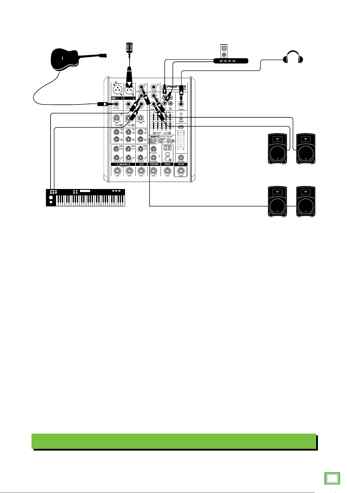
This diagram shows an acoustic guitar plugged into the channel 1 line input with the line/hi-z switch
engaged. A microphone is connected to the channel 2 XLR input for vocals and a keyboard is attached
to the channel 3-4 line-level inputs. An iPod docking station is attached to the stereo tape inputs.
Thump15 powered speakers are connected to the left and right main output. Two of these speakers are
also set up as stage monitors and connect to the mixer's monitor output. The aux mon controls of each
channel allow you to create a stage monitor mix as desired, while headphones are used for monitoring.
Typical Live Sound System
Owner’s Manual
5
ProFX4v2
48V
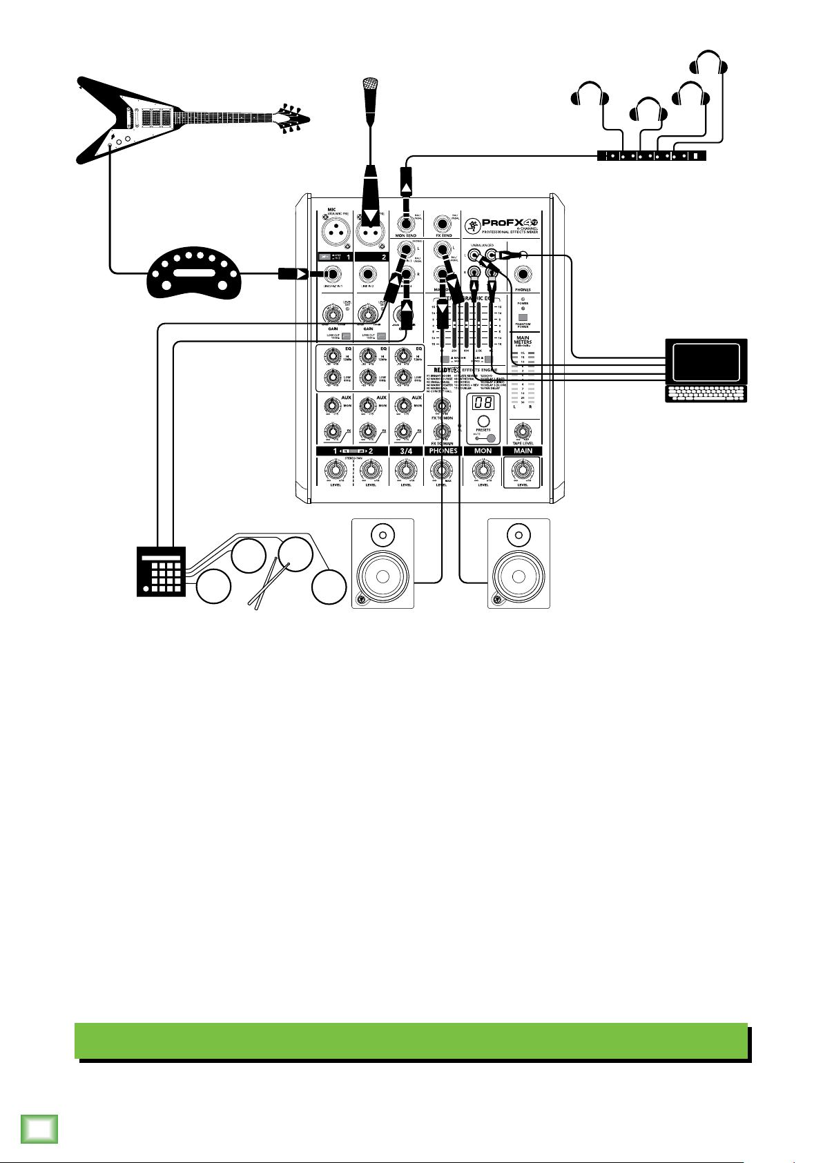
This diagram shows a Flying V plugged into a modeling device which is then connected to the channel
1 line input with the line/hi-z switch disengaged. [The modeling device is at line-level, not instrument].
A microphone is connected to the channel 2 XLR input for vocals and a drum machine is attached to the
channel 3-4 line-level inputs.
MR8mk3 powered reference monitors are connected to the left and right main output. Headphones
connected to the mon send via a headphone amp are available for the talent to utilize when tracking.
A laptop connects to the stereo tape inputs and outputs to record the 2-channel main mix to the DAW,
as well as play back two channels from the DAW.
Typical Recording System
6
ProFX4v2
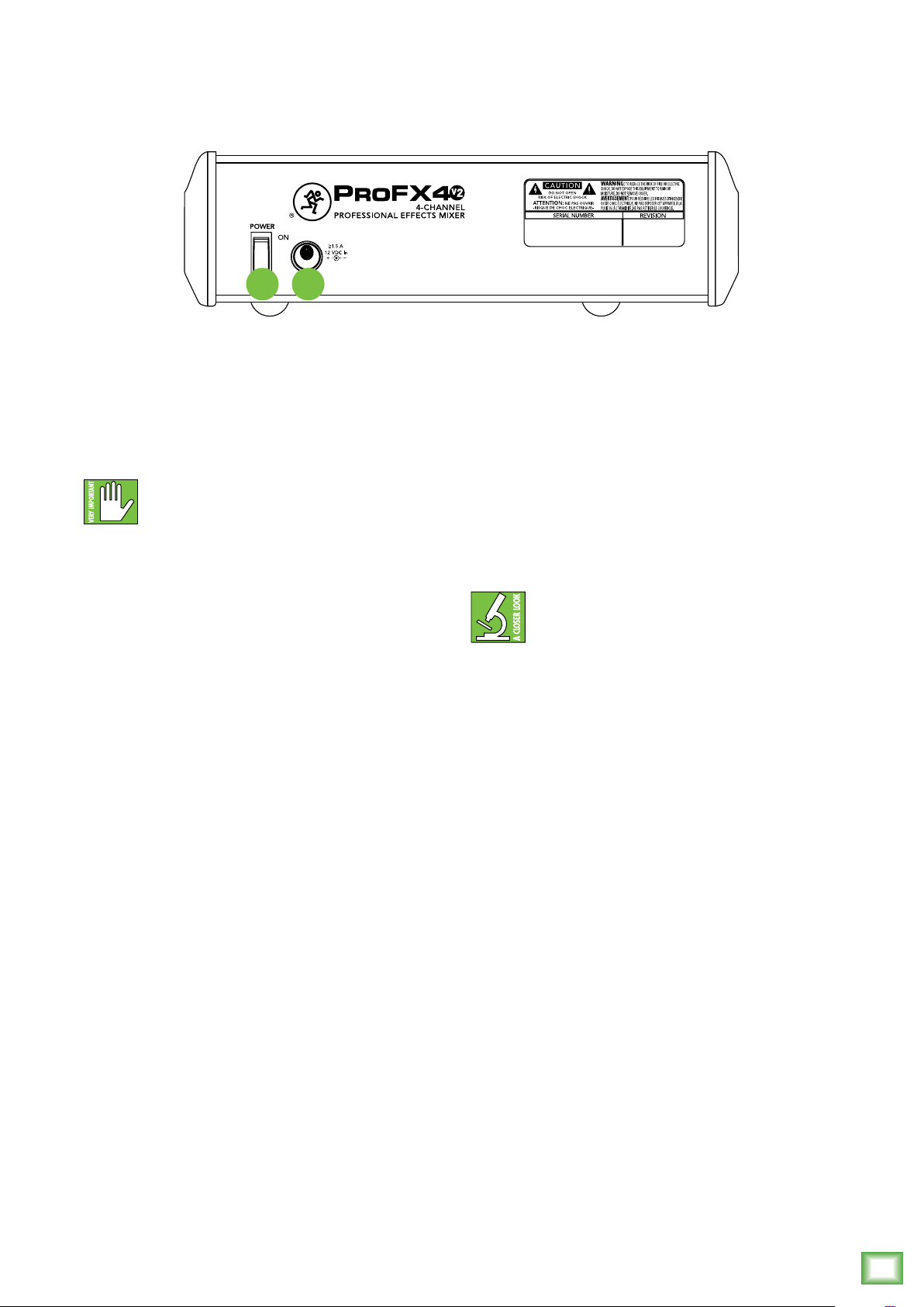
ProFX4v2 Rear Panel Features
2 1
Owner’s Manual
1. Power Connection
Push the 2-pin female side of the power adaptor
securely into the connector on the rear of the mixer.
Plug the other end into an AC outlet properly configured
with the correct voltage as indicated on the AC adaptor.
Only use the AC adapter that came with your
mixer, or a factory-authorized power supply.
2. Power Switch
Press the top of this rocker switch inwards to turn on
the mixer. The front panel power LED will glow with
happiness...or at least it will if you have the mixer's AC
adaptor plugged into a suitable live AC mains supply.
Press the bottom of this switch to put the mixer
into standby mode. It will not function, but the external
power supply is still live. To remove power, either turn
off the mains supply, or unplug the AC adaptor from
the mixer and the mains supply.
As a general guide, you should turn on the
mixer first, before any external power
amplifiers or powered speakers, and turn it off
last. This will reduce the possibility of any turn-on, or
turn-off thumps in your speakers.
Owner’s Manual
7
ProFX4v2 Front Panel Features
2
Connections and Channel Strip
The vertical channel strips look very similar
and have only a few differences between them.
ProFX4v2
Each channel works independently and just controls
the signals plugged into the inputs directly above them.
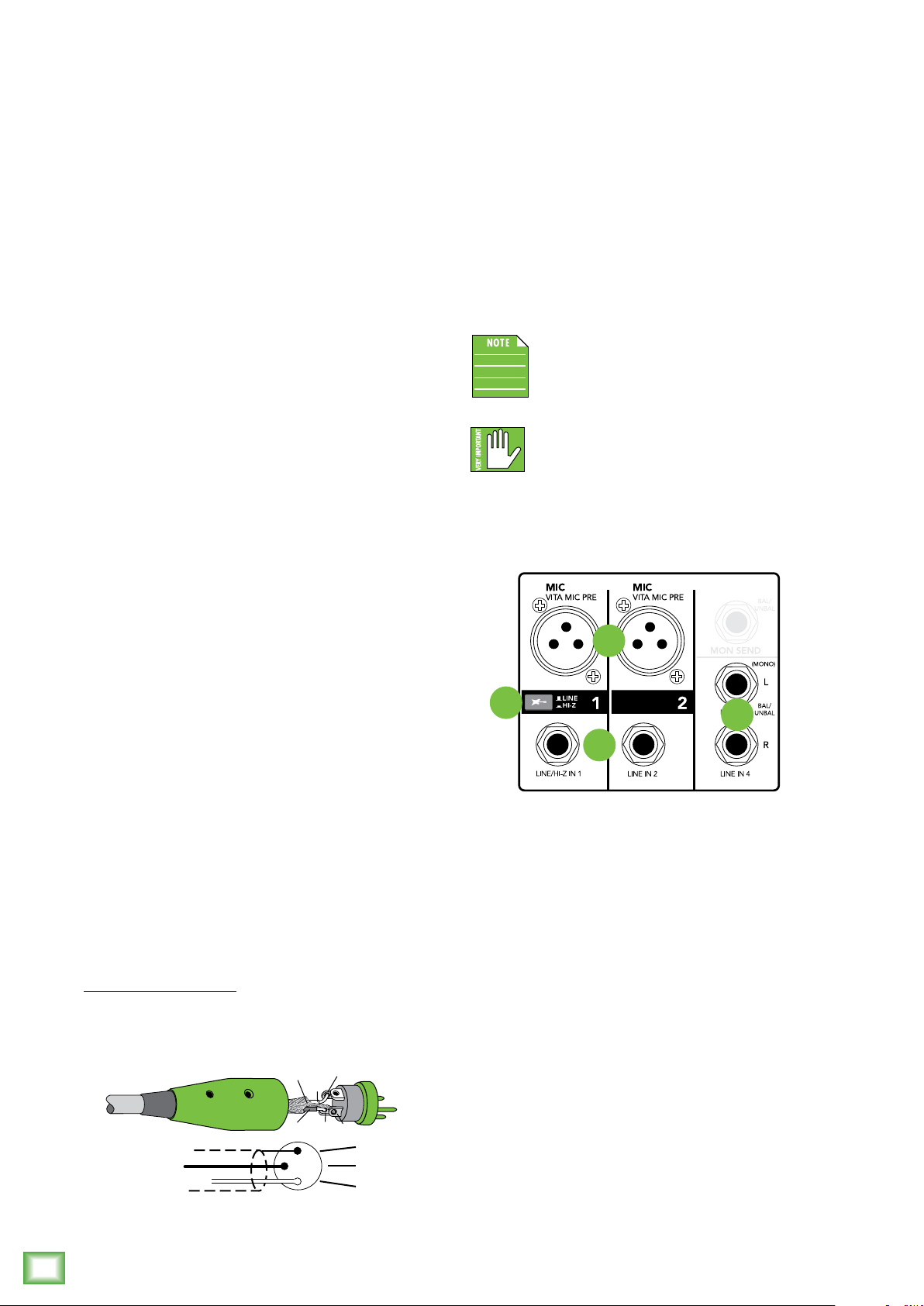
3. Mic Inputs
ProFX4v2 mixers use 3-pin female XLR connectors
on all microphone inputs, with pin 1 wired to the
grounded (earthed) shield, pin 2 wired to the high
(hot or positive polarity) side of the audio signal
and pin 3 wired to the low (cold or negative polarity)
side of the signal.
These female XLR connectors accept balanced
mics or line level inputs from almost any type of
source. The Vita mic preamps feature higher fidelity
and headroom rivaling any standalone mic preamp
on the market today.
Phantom Power
Most modern professional condenser mics require
48V phantom power which lets the mixer send
low-current DC voltage to the mic’s electronics
through the same wires that carry audio. (Semi-pro
condenser mics often have batteries to accomplish
the same thing.) “Phantom” owes its name to an ability
to be “unseen” by dynamic mics (Shure SM57/SM58,
for instance), which don’t need external power and
aren’t affected by it anyway.
The ProFX4v2 mixer’s phantom power is
globally controlled by the phantom power
switch (meaning that phantom power for
both mic inputs is turned on and off together.)
Never plug single-ended (unbalanced)
micro phones or ribbon microphones into
the mic input jacks if phantom power is on. Do
not plug instrument outputs into the mic input jacks
with phantom power on unless you know for certain it
is safe to do so.
We use phantom-powered, balanced inputs just like
the big mega-consoles, for exactly the same reason: This
kind of circuit is excellent at rejecting hum and noise.
Professional ribbon, dynamic, and condenser
mics all sound excellent through these inputs.
The mic/line inputs will handle any kind of level
you can toss at them, without overloading.
Microphone-level signals are passed through the
mixer's splendid microphone preamplifiers to become
line-level signals. They are wired as follows, according
to standards specified by the AES (Audio Engineering
Society).
XLR Balanced Wiring:
Pin 1 = Shield (ground)
Pin 2 = Positive (+ or hot)
Pin 3 = Negative (– or cold)
SHIELD
HOT
1
3
COLD
1
3
2
SHIELD
COLD
HOT
3
4
6
5
4. Line / Hi-Z Switch
To connect a guitar directly to the mixer without
using a DI Box, press this switch in first; then connect
the output from the guitar to channel 1's 1⁄4" TRS
input. The input impedance is optimized for direct
connection and high-frequency fidelity is assured.
In the out position, channel 1's 1⁄4" TRS input
becomes a line input just like the other mono line
inputs.
To use guitars or other instruments on other
channels, you will need to use an external DI box
first. Without the DI box – or if this switch is not
pressed in – guitars may sound dull and muddy.
8
ProFX4v2
 Loading...